V/I class A Amplifier

892022d1605021500-class-amplifier-vi-classa-mos-jpg


This is two amplifiers combined in push pull. The main power amp is made of open loop current amplifier T4,T5. The bias is adjusted by R5, 1.3A and the transconductance by R7. The second amplifier is also a transconductance with feedback to provide a low impedance output.
This is a quick feasibility circuit of 10w, with mosfet it is about 0.05% THD and the double with bjt version.
Hayk

Attachments

  • VI CLASSA MOS.JPG
    VI CLASSA MOS.JPG
    123.6 KB · Views: 1,649
  • VI CLASSA.JPG
    VI CLASSA.JPG
    135.4 KB · Views: 698

FS: MM Phono Preamp

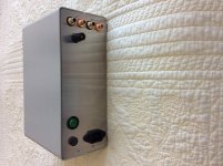
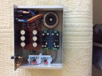
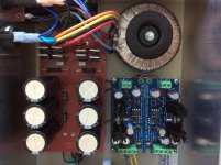
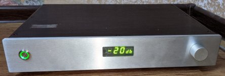
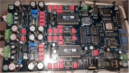
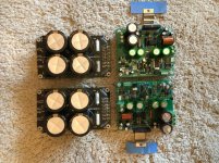
This phono preamp is based on the circuit for an ultra low noise RIAA phono preamplifier in Texas Instruments Application Report AN-222 “Super Matched Bipolar Transistor Pair”. The matched transistor pair replace the input transistors of an opamp. The circuit was designed for the LM394 transistor pair, which was discontinued. My board uses the (pricey) Analog Devices MAT12 replacement. The IC is an LM318, as noted on the application report.
The raw power supply is 6L6’s version of the Pass Pearl2 supply, and a Jung/Diddden Super Regulator coverts it to +-15V for the phono board.
This is a very smooth, quiet preamp.
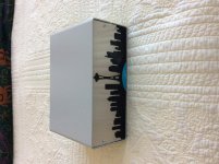
Dimensions: 4.25H x 10L x 8.25D (inches). That is a laser cut LP of the Seattle skyline on the front.
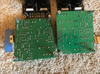
Documentation and extra pcbs (raw ps and phono) included.
$100, OBO, shipping to CUS only

11/19/2020 ***SOLD***

Attachments

  • 27463E4D-9872-4FAE-B3DE-6545A6FBEDCB.jpg
    27463E4D-9872-4FAE-B3DE-6545A6FBEDCB.jpg
    443.9 KB · Views: 524
  • B8B9BE78-57B2-4BB9-951C-7CC2E7C9E71F.jpg
    B8B9BE78-57B2-4BB9-951C-7CC2E7C9E71F.jpg
    451 KB · Views: 521
  • 1A4C6AD8-6E4E-4560-B5DF-E0B9486F5A69.jpg
    1A4C6AD8-6E4E-4560-B5DF-E0B9486F5A69.jpg
    539.8 KB · Views: 514
  • F34D50FB-D370-4283-9C92-DEA42FE4DBFD.jpg
    F34D50FB-D370-4283-9C92-DEA42FE4DBFD.jpg
    568.2 KB · Views: 509
  • 07665E49-E74F-4FCD-9F54-E6B6A347DDB1.jpg
    07665E49-E74F-4FCD-9F54-E6B6A347DDB1.jpg
    500 KB · Views: 497

Best choice for Aleph 30 re-cap

Hi,

A friend brought his original Pass Labs Aleph 3 to me to check out a couple of weeks ago, and when I peeked under the hood I could see some of the power supply filter caps had crowned tops. The little 220uf caps all tested high for ESR, so I changed all the electrolytics out for the original factory values. Now that friend has brought me his Aleph 30. The caps in this amp don't show physical deformities, but since it's a 17 year old Class A amp and easy to work on, I'm going to replace them.

The Aleph 30 is an improvement over the 3, so I'm curious about the difference in total capacitance in the power supply:

  • Aleph 3 stock caps: Panasonic UP 25v 22,000uf x 8 = 176,000uf
  • Aleph 30 stock caps: Panasonic UP 50v 10,000uf x 12 = 120,000uf
Is the reduction in total capacitance relevant or was the value in original Aleph 3 simply overkill?

I've gone through various replacement options offered by Digikey, and have narrowed my choice down to the following:

  1. CDE 380LX 50v 10,000uf x 12 = 120,000uf
  2. Nichicon LLS 35v 15,000uf x 12 = 180,000uf
There are no 105c rated caps that will fit in this application. I understand the 50v rating is higher than needed, so would the additional capacitance offered by the 35v Nichicon caps a point in their favour? I know they are both well respected brands. Or am I overthinking a trivial detail?

I'll use Nichicon KA for the 220uf values.

Thanks in advance.

Crown DC-300A II Restore with Measurements

Hello Everyone!

This is the first of several posts I’m going to make in this thread. This is the first time in a few years that I’ve posted on an online forum and will try not to make a mess of it.

Background

This is yet another DC-300A II refurbish experience that in my case was world’s easier than the Amazing Effort by Shawn 10 years ago. This is because I cheated and bought one that was already in good condition. It was sold initially to a home owner in Canada that made its way to the US, then finally to me a few weeks ago via FleaBay™. I spent (2) days on it and a couple of weeks deciding on and waiting for parts orders. The one thing that will be different about this post is that I’m a measurement nut. Audio, to a large extent, is a means to an end of empirical learning for me and if you’re foolish enough to follow along, I bet you too will see some stuff you haven’t come across before. 🙂

Though I’ve finished the refurbish, I haven’t listened to the amp yet. I was afraid to connect it to my loudspeakers prior to measurement and afterwards figured the "before" listening experience wouldn’t be indicative of a new OEM unit anyway. I’ll add a post to this thread in a week or so after doing some serious listening and see if this amp really earns its broken glass with good bass reputation.

Per Shawn’s and a few others comments both here and on the Crown Forum, and the good initial condition of the amp, I chose just to upgrade the electrolytic and ceramic disc capacitors and leave it at that. The 1N270 germanium diodes used in the limiting circuitry work properly, so I left them in place though I did buy spares for the future in case they become unobtainum.

OEM Parts to Upgrade

View attachment DC-300A II OEM.pdf

Replacement Parts

View attachment DC-300A II MOD.pdf

And for completeness, here’s a link to the Service Manual and the Owner's Manual.

Finally, as will be seen in following posts, what’s inside now matches the pretty outside:

Front.jpg

Rear.JPG

Digital versus normal interconnect cable

Hi
I made some digital interconect cables from special, very flexible, 75 Ohm video cables and compared them with regular high quality interconnect cables on my scope, the selfmade digital cables show faster edge rise time time on the digital trace, 7 nS instead of 21 nS, did anyone else measure that? Must try and do some listening tests....
Cheers, Tom.

My LM1875 Build Thread (chip amp)

Hello forum members

This is my 1st chip amp construction thread ... LM1875, a little project that has been kicking about for a while. I don't really need to make one, but was attracted by the simple construction that could be achieved ... and for some reason really liked the PCB layout with noise cancelling ideas applied to the track layouts that seems to be a new skill amongst PCB designers .. so will allow the pictures to tell the story
I decided to make my own post instead of high-jacking another members post ...

Using SE Output Xfmr with 5K and 8K Impedance as Ultralinear?

So mainly a question out of curiosity, but is there any problem with using a single-ended output transformer with 5K and 8K taps as an ultralinear setup with a KT77 power tube? Plate voltage would be in the 350V range and transformer is rated for 15W

I realize it's not the standard 40% ultralinear tap, but I have this transformer and tube sitting around and was thinking about building something just for experimentation sake, because if it worked reasonably well it might be cool. The KT77 datasheet says it can be used as a tetrode but screen voltage should not exceed 300V (while design max is 600V for ultralinear). My datasheet has little to no info on a single-ended setup, so basically I was just checking to see if this sounded like a catastrophic failure waiting to happen or potentially doable.

Thanks.

Building enclosure quesions? Stuffing and binding post and more?

Good Evening everyone. I am building a few boxes and I read on one of the building blue prints. It said Don't use egg shape foam for the inside of a box for sound absorbing for the back sound waves. Why not? I have never had trouble with this egg shape foam before? I was told to use cotton or wool felt instead? Why not Acousta suff poly fill? So on to the next question? Binding post made of 100% copper sounds better then brass? I keep reading this? Does it really make a night and day improvement? I just wanted to get every ones thoughts on these clams? Thanks for your help. Jeff

Solder question

Hi,

Really a question out of curiosity more than anything else. Today I was messing around with a piece of hi-fi which had a faulty internal PSU and wanted to change it for a spare and to do this I needed to swap a 4 core connecting cable which was soldered into the PSU.

I first tried unsoldering the cables using a small electronics specific soldering iron which I think is 60 to 75 watts - the type with a conical point. The solder just didn't want to melt so tried my Weller soldering iron which is probably a couple of hundred watts. Again couldnt get the solder to melt even though the cable was getting too hot to hold where I was gripping it a few cms from the joint and the sheath was almost melting!

Playing with circuit boards is not something I do very often, so maybe my technique was wrong, but as I said there were 4 wires and not one came out easily, even using the Weller. So curious as to whether some manufacturers might use higher melting solder?

Any comments appreciated.

Alchad

FS: DSC DAC (very custom version)

Here is a (as I can call it) very custom version of the DSC DAC for sale.

Price is $1.3k (~1.1$k for the parts + assembling fee) + shipment.

It is based on the DSC v.2.5.2 board + PPY's reclocker (NDK SDA) + BBB + my output transformers + relay volume attenuator with RC.

All the boards (excluding volume control) are powered from linear K&K PSUs (LT3080) and shunted with ultracaps.

This DAC can accept the DSD stream only (not PCM). The best possible way is to use the HQPlayer, to which this DAC will be connected through the LAN (RJ45 on the rear - input interface of the BeagleBoneBlack SBC) as NAA endpoint device. Roon-bridge is possible too.
Disclaimer 🙂 Due to complexity of the connection type and irregular usage way for this DAC, I can not positioning it as a "branded" DAC. It is better to regard it as a finished DIY-project. I can not give to the buyer any long term warranty in this manner. The buyer should be ready for such kind of DAC. The dedicated server with HQP (Roon+HQP) is prefered for connect this DAC to.

Regarding the sound quality. I can say that this particular DAC paired with HQP4 (ASDM7EC x256 modulator) easily outperforms the PSAudio DirectStream Dac.

DSC_front.jpg
DSC_coveroff.jpg
DSC_rear.jpg

Hifonics Hercules H35 3000.1d

I have a Hifonics Hercules 35th Anniversary Edition model H35-3000.1d that would go into protection mode when too much current is supply and would stay solid green when little current is applied but no sound whatsoever. Installed into my car to see if it was just the power supply that im using to power the amp was making it go into protection but the lights would flash from red to green. Opened up the amp and everything looks fine. Nothing looks blown. Could anyone help me? Thanks.

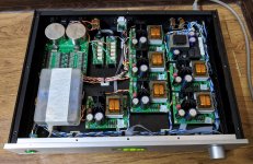
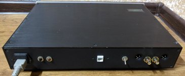
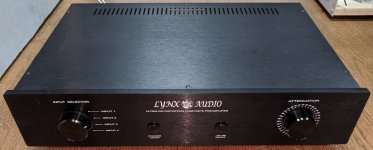
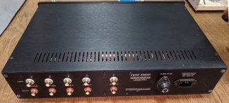
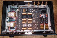
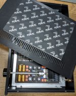
FS: LynxAudio P71 preamplifier (Author's edition)

The author's (Dmitry Andronnikov) version of LynxAudio P71 preamplifier is for sale. Was purchased for $3.3k in 2014.
Price is... Let's start from $2k (excluding shipment from Almaty, Kazakhstan).

Translation of the annotation to English is just for reference (google-translate).

P71_front.jpg

P71_rear.jpg

P71_inside.jpg

P71_cover.jpg


p.s. Author's amplifier PA72, mentioned in the article is available too for $2.3k

View attachment Lynx_P71_english.pdf

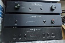
FS: LynxAudio PA72 amplifier (Author's edition)

The author's (Dmitry Andronnikov) version of LynxAudio PA72 amplifier is for sale. Was purchased for $3.8k in 2014.
Price is... Let's start from $2.3k (excluding shipment from Almaty, Kazakhstan).

Translation of the annotation to English is just for reference (google-translate).

PA72 is in the middle on the photo (P71 preamplifier, D48V4 DAC are for sale too)

P71, PA72, D48.jpg

View attachment Lynx_PA72A_english.pdf

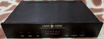
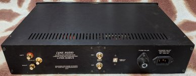
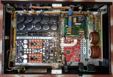
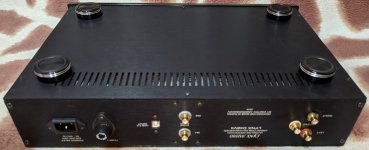
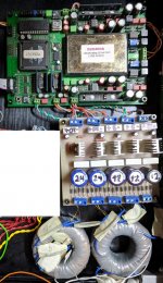
FS: LynxAudio DAC D48V4 (Author's edition)

DAC is from the TOP league, based on ES9018S chip.
3 inputs: 2xSPDIF, USB (Edel)

This DAC was purchased in 2014 directly from author of this device Dmitry Andronnikov (it was his own "home" version). Price was $10k.

Sale price now is... Let's start from $4k (excluding shipment).
Weight is ~7.8kg, ~10kg with package. Shipment from Almaty (Kazakhstan).

Dmitry has not made the documentation exactly for this DAC version (as probably I suppose it was the single sample), the approx. documentation relates to previous version and can be found in pdf.

front.jpg

Back.jpg

Inside.jpg

bottom.jpg

View attachment Lynx_D48.eng_opt.pdf

FS: LynxAudio DAC D30a (UltraAnalog D20400a)

For sale is the CDDA-format DAC board based on legendary D20400a microcircuit with PSU, that was made by Dmitry Andronnikov.
Was tested with RJ24 input data.
Price is $1.6k + shipment
D30aFS.jpg
Can be supplied with SPDIF/USB input interface or/and in chassis as a finished device for extra payment.

Here is the draft translation (google-translate) of the article for this DAC:

View attachment DAC_Lynx30a.ru.en_opt.pdf

FS: LynxAudio Lynx24 DAC (2xAD1865)

CDDA (16x44.1) DAC board Lynx24 based on AD1865 in differential mode is for sale. PSU is also included. Tested from Teac VRDS-transport via LVDS-interface: RJ24 (48fs). Possibility of connection via SPDIF or USB-I2S converters can be given for buyer on request.
Price is $1k + shipment.

Lynx24.jpg


Here is the article (google-translated) for this DAC from manufacturer (Dmitry Andronnikov).

View attachment DAC_Lynx24.ru.en.pdf

Cornscala dampening or not

HI, New to the forum and have a question.


I have Crites Cornscala Type B and I purchased a complete speaker set. He makes the cabinets out of good Birch plywood but there is no packing or dampening in the cabinet. I have some carpet pad. Is there benefit to wrapping the horn and walls? Is there any chance the screws will strip out if I remove the back of the cabinet? Thank you.

Inductor Loaded De-Lite

Hi guys, quick question for you. Maybe I'm on to something, or maybe I'm way off base.

Could the 300 watt light bulb power resistor in the De-Lite circuit be replaced by a high current inductor, such as the Hammond 193V (150mH, 1 ohm, 3A max DC). Would such a change require a complete redesign of the circuit? Would it be easier to start from scratch? I'm assuming at the very least the power supply voltage would be lower, since the inductor can store so much energy. Can the inductance of the inductor make up for the loss of load resistance the light bulb supplied?

Since completing my ACA, I've been looking at solid state designs using some iron in the amplifier circuit, like the Nemesis, FAOW #2, and MoFo. For one reason or another, they don't quite satisfy my requirements. I like the De-Lite circuit, ruthlessly simple with no NFB. The added efficiency of an inductor makes the circuit more attractive. I tried doing a simulation of my circuit idea, but didn't get very far. I also don't know which version of the De-Lite would be best suited to this modification, I was thinking the De-Luxe circuit.

If this is a completely silly idea, please say so! If not, I'd love to to hear your guys' thoughts!

Mexmerize 10 Years After questions

I am building a Mesmerize DCB1 with what I believe is the latest PCB from the store. I have downloaded the build notes and schematic but am confused about a couple resistor values.

The schematic is difficult to read because much of the lettering is overlapping. Perhaps I need a different reader? If I could read this more clearly I could decipher the resistor values.

The paired resistors that connect to Q1 and Q3 appear to be 470R on the schematic but the board is marked 68R. The BOM seems to indicate 18R

The BOM indicates 2 1R resistors in the PUS section (R13 and R20 on schematic). Are these 10R on the PCB?

Thanks for all suggestions.

SMPS for filament heating of power triodes?

Its been a very long time ago since I am resisting te idea of using an SMPS for heating my tubes, but lately I am toying around really big flaments in the class of 10 to 30 amperes and the SPMS seems the way to go especially considering that SMPS technology has advanced alot. My initial tests with an old PC power supply are good, although alot of HF random noise is (checked this with my scope) present at the output of the supply but is not making its way at my speakers (ears anyway) at all.
So, my question is, has anybody any suggestion for lets say 5V 30-40A capable SMPS with good noise figures diy or ready made?

I checked and there seems to be a huge avalability of very good quality SMPSs from servers which seem excellently made, power factor corrected and very small too!

On the other hand maybe is time to start a colaborative project for a dedicated SPMS for our Tube experiments as SPMS technology seems very advanced and available too.

Help Trouble Shooting Marantz Tonearm Wiring

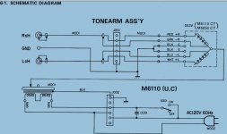
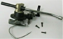
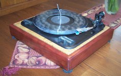
I added a Marantz 6110 tonearm to an old Garrard Type A MkII, and built a custom plinth for it. I'm getting sound from both channels, but there's no left to right balance change when I turn the balance knob back and forth....still get sound from both channels.

I did some continuity checks from the tonearm wire connections at the RCA output jacks on the TT to the cartridge leads at the cart body, and get continuity signal through all 4 leads independently (as expected), however I also get a continuity signal from the green ground lead on the right channel when I touch the cart's metal body with the probe....not the case for any of the leads. I'm not experienced enough to know if this is normal...I suspect not, and wonder if it's the cause of the balance issue, and have no idea why this would happen. I changed headshells and carts just to eliminate a possible cause....same result (AT-3600L to AT-80E). The tonearm wires are connected as per the service manual diagram (shown below)

I'd appreciate any thoughts on what the issue could be.

6110 tonearm diagram.JPG 6110TA.jpg 000_4019.JPG

noob > bypassing/removing pot/potentiometer

Hi folks,

I have this Tc Electronic Konnekt 24d audio interface with a broken volume knob.
I don't need the knob at all, since I use 3 channels (2.1) and the knob will only change volume for 2 channels anyways.
So I would like to remove it, or bypass it, or whatever I can do to take the defective knob out of the equasion (100% volume).

I have no clue about electronics, but I used a soldering iron before.

what is the easiest way to do this?

the knob should be this:
An externally hosted image should be here but it was not working when we last tested it.


EDIT: took the picture from this other thread: Changing a pot's value with parallel resistors
it actualy seams to be the pre-amp pot, not the volume pot which is stereo

FS: Antek AS-4218 Toroid

****UPDATE****

The transformer has been sold!


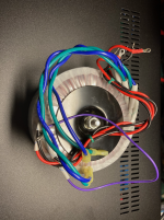
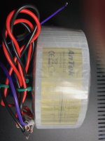
For sale, 1 Antek AS-4218 toroidal power transformer. Suitable for a Pass-style Class A amp.

Specs:
  • 400 VA
  • 2 X 18 Volt secondaries
  • 2 x 120 VAC Primaries
  • Shielded
Complete specs here: https://www.antekinc.com/content/AS-4218.pdf

Only used for bench testing a PSU - I don't need it anymore since I ended up with a different voltage unit for my amp build.

The leads are original length, but I have put crimp-on .25 inch Fastons on the secondary leads and soldered-on ring terminals on the primary leads. You can cut them off if you don't want to use them. It has the factory mounting washers and bolt as shown.

$35 + shipping. PayPal. PM me.

Attachments

  • IMG_0989.png
    IMG_0989.png
    729.6 KB · Views: 149
  • IMG_0990.png
    IMG_0990.png
    602.9 KB · Views: 150

Hello from Herts. UK

It was at the start of lockdown....there are going to be lots of these kind of stories but I decided to play some more vinyl so needed an amp upstairs. I pinched the NAD 302 from the dining room and therefore needed a replacement. Aha! I have an old amp in the loft so up I went and down came an early 70s Wharefdale Linton and a pile of dust. There actually wasn't much wrong bar lots of duff wiring (single core...hmm), some utterly past-it caps and a couple of dry joints which must have been there since manufacture. I sorted it all out - and the case - and it sounds sweet as a sweet thing paired with my B&W CM1s. Cue bloke in pub with a NAD 3020 which I then sorted out (caps again), and that was it, hooked. Mostly NADs so far, all donated or bought from flea-bay as non-working; another 302, C340, 3020e, 7225PE and a couple of CD players. O yes - and a T773 I picked up for £25 on which all the output stages work! I was led here searching for info with the 7225 getting very warm after replacing all the semis from bias out after some "event" which left the leads of a resistor (the 180 ohm one between the drivers) but nothing else! Some great info and hopefully I will be able to contribute in time. Cheers!

Martin logan CLX mods

The Martin Logan CLX (and the rest of their ESL line) can benefit from some selective upgrading.
Doing these mods will likely void your warranty, possibly reduce the resale value, and you are working on equipment which has AC input and high voltage supplies, so unless you know what you are doing and the speakers have been de-engerigized (AC and audio cables disconnected for a few days) then leave them alone.

Now that you've been advised and I've scared you all off here goes.

1. Remove the AC power cord from the speaker and leave them sit upowered for a couple of days to make sure they are dischaged.

2. Cover the FULL area of the speaker and cells on all sides with thick cardboard to avoid any damage while you work on them. tape up all edges. This is not negociable ! - a solder splash or drilling debris can damage your cells or finish!

Your preference and choice of wire, capacitors, and connectors may well differ as will which mods are of interest or fit your budget or skill set.

1. Speaker connectors - Martin Logan had a speaker connector made which looks sustanstial - I've had 2 break. I replaced them with WBT 730.12 platinum using the original Martin Logan plastic isolators. This requires using a drill with a 90 degree chuck and drilling out PART of the existing hole. Looks very good.

2. AC input connector - replace with an AC line filter -I used a Tyco C6EEJ1 or similar - you'll need to open the hole a little to get it to fit. I also like to use a 3.3 uf X2 rated cap such as Vishay BFC233820335 after the filter and put the whole assembly in a giant piece of UL approved heatshrink. The filter cap must be an X2 rated cap - no audiophile cap will do and would be unsafe!! This assembly must only use UL approved components and be installed in a safe and secure manner. Check with an ohmmeter for high impedance to ground for each of the Line to Line or line to Neutral wires after you finish and BEFORE connecting.

3. Wire. Martin logan used a UL approved TEW custom made copper cable for audio wire. I replaced it with DH labs Q 10 Teflon insulated silver plated OFC copper .

4. There are 4 Solen caps in the crossover board.
This is the biggest area for improvement. The planar resistors on the crossover boards are EASY TO DAMAGE and you will have a hard time to replace them without damaging the board so do this work on a old thick towel very carefully!!!! The original caps cost about $30 a speaker and the new ones will run about $1,000 total so this isn't inexpensive, but I don't know how to achive the same sonic improvement (and physically fits) any other way. I used Plumbers goop to hold the caps - much better than silicon, but don't make mistakes - it's also extremely much harder to remove once it sets.

The crossover caps are 2 x 22uf, 1 x 33 uf, 1 x 1.5 uf

22uf - replaced with a parrallel sandwich of 2 x 9 uf 100V MIT PPFXS , a 3 uf /100v MIT PPFXS, a 0.33uf /600v MIT RTX and a 01./600V MIT RTX. ( this totals 21 uf, but the MITs I had are a little over value and i selected mine to add up to the 22uf) The 2 x 9 uf and 0.01 uf caps fit where the Solens did and by using both PC boards you'll find you can put the 3 uf and the 0.33 uf with wire leads on the LF board without blocking the air flow to the planer resistors and when the 2 boards are joined the leads soldered to join the caps up and make the required value.

Note - The 9uf MIT PPFXS cap is the largest cap with the same width of the Solen caps which is why it was chosen - becuase it fits, takes the least space, and sounds good.

Don't block the airflow to the planer resistors.
I measured a 4 C rise with my mods on the resistor bodies - you really don't want the speakers on a carpeted floor blocking off the air flow intakes - make small granite platforms for them.

The 1.5 uf cap - use PPFXS 1.5 uf.

The 33 uf cap - replaced with a parrallel sandwich of 3 x 9 uf 100V MIT PPFXS , a 5 uf /100v MIT PPFXS, a 0.33uf /600v MIT RTX and a 01./600V MIT RTX. (this totals 32.34 uf, but the MITs I had are a little over value and I selected mine to add up to the 33uf) The 0.33 uf and 0.01 uf caps fit where the 33 uf Solen did . The rest of the PPFXS caps have to assembeled together off board and the leads brought back to the crossover board.

There are 2 ways to do this - I got rid of the components on the board which joins the cells to the transformer and mounted the 33uf's PPFXS caps there and hard wired the cells to the transformers - not as easy to service, but i prefer direct hard wired connections so I would have done it anyway and it left me with a place to mount the 33uf's PPFXS caps - otherwise you can keep the transformer to cell interface board stock and you'll have to mount the 33uf's PPFXS caps on a PC board and heatshrink the whole assembly and install it where it doesn't interfer - it must be insulated so it doesn't short against anything. (near the speaker input jacks there is some space).

5. The Fet turn on board (the lower PC board with heat sinks) has 4 of 0.33 uf/ 250 volt caps on it bypassing the IRF 640 Power fets - Replace with MIT PPFXS 0.33 uf.

6. The Fet turn on board also has 4 of 100uf/35v 85C Jamicon electrolytics - I prefer Panasonic FM or Nichicon HE series caps - both 105 C for long term reliability. Warning - this is a double sided board and unless you are very good at soldering , and have a good hot iron, solder wick, and lots of experience don't do it.
This is no place for an audio rated electrolytic cap like Silmic or Blackgate (which i like ) - it just does electronic housekeeping and it doesn't pass the audio signal that you hear.

7. The high voltge power supply board ( with 2 small black transformers on it) has about 10 of the 85C Jamicon electrolytics - again I prefer Panasonic FM or Nichicon HE both 105 C for long term reliability. Warning - this is a double sided board and unless you are very good at soldering , and have a good hot iron, solder wick, and lots of experience don't do it.

I also removed the LM 358's and socketed them - again years of soldering experience on boards is needed , a good hot soldering iron with solder wick is required - it is a double sided board and easy to lift tracks.

Next part ONLY FOR SKILLED MODDERS

I got rid of the transformers to cell interface board connections and the Molex connector between the cross over board . This makes it harder to service - you need to remove the crossover board, the inter-connect board, and the fet turn on board all together to service them, I did it several times durirng the mods as the updates progressed and it wasn't too hard. But some may not go this far ...


The end result - after a 75 hour burn-in - a much smoother, far more resolving sound, and superb detail. The structure of notes has higher intial impact and greater harmonic detail to the decay. Dynamics are improved as well. I couldn't go back to the original version.

pictures to follow .............................

A beautiful BJT bias scheme.

The schematic attached shows a single BJT oscillator using a biasing scheme which I found very interesting, and efficient. The 10kHz output sinewave is very clean considering the simplicity of the circuit. The oscillator uses an LC parallel resonator as the transistor's output. It taps some of its energy into a short coil to feed the base.

Inspection of the various currents under LTSpice shows that the LC resonator receives an energy pulse for a very short time during each cycle.

Attachments

FS: NC502MP and NC252MP modules

I have two NC502MP and two NC252MP modules I had acquired before becoming a Hypex OEM distributor/builder so I want to sell them off since I will not be using them for official builds (for obvious reasons).

These are brand new, only used for testing of functionality.

$399 shipped for each NC502, $740 for both
$299 shipped for each NC252, $550 for both

***See my other listing for a 2U, 17" wide ModUShop aluminum case...perfect pairing for a four channel build***

Recap info Harrison 32C PSU

Hi, I’m in need of some feedback for recapping the PSU of my Harrison 32 series. When analyzing the schematics and determinizing what is electrolyte/film/tantalum (I hope) I’m now in the process of ordering the caps. This is quite a challenge because many caps are hard to get. I need a variety of capacity and voltage, some types are very expensive in small quantities at digikey-RS-Mouser-Farnell.
First, can I deviate in the capacity, for example from 520 to 560µF - 1100 to1200µF - 32000µF to 33000µF? These are mostly the smoothing/decoupling caps.
Sec, Voltage specs, as long they match or higher I’m good?
Most of them are Axial, Radial is no problem as long there is space?
3rd, are caps without polarity (ex. Sprague 0.1 80VDC) indication film/foil caps? Do they even need recapping?
Thanx for any feedback!

Digital Design DM 2500

Hi Guys i have a bit of a strange problem with this amp. Not going to go into to much details but the amp came in with outputs faulty. Replaced those but amp was still in protection. Found that there was a in the power with one of pair of driver transistors. So to be safe removed all the power and output fets and replaced the pair of power driver transistors. Powered up amp and still protection. now these drivers power drivers and fed by a 100ohm resistor which measured fine but i removed it just to see what was going on. With the resistor out amp powers up fine and i get my wave form on gate pads of all the other banks in the power supply. Once i put in another 100ohm the waveform goes away. now knowing the fault is within the drive circuit. I went ahead and built just that one part of the drive circuit using BD139 and140. Soldered just the base and collector using wires from the BD transistor to the board and I get my waveform on the emitters

Now once I take the wire solder on the emitter and connect a 47 ohm and then touch on the gate pads for that bank of fets the waveform goes away. even removed the transformer and still the same result no waveform only when that bank of drivers is connected. when that bank of drivers is removed i get wave on all the other banks as well as pin 9 and 10 of tl494.

Here are the pics

Attachments

  • IMG_20201118_135418.jpg
    IMG_20201118_135418.jpg
    279.4 KB · Views: 62
  • IMG_20201118_135513.jpg
    IMG_20201118_135513.jpg
    1,001 KB · Views: 62

diy double trapped vent

Hello to all,

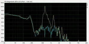
After several trials I built a vent that successfully kills pipe resonances. It's a simple pvc drain tube fitted with two closed traps of the same diameter stuffed with polyster fibers. Dimensions in the photo/drawing. I made the vent very long to enhance resonances spl. The second trap was necessary to kill the H2 at 1230Hz. BTW, I built also a vent with some holes in its middle and the result is OK, but not as efficient as the double trap system, mainly on the H2.
Placement of the traps: the longer one has to be the further from the exit. The respective axes of the traps are not important. I didn't play with the traps center distances.

If someone could model my system I would be very happy.
🙂

Attachments

  • évent double-trapé vs évent simple tube.JPG
    évent double-trapé vs évent simple tube.JPG
    131.5 KB · Views: 407
  • double trap vent.jpg
    double trap vent.jpg
    187.1 KB · Views: 416
  • Like
Reactions: stv

different audio forum

Good evening.

I have some questions that I would like to ask in plain and simple language and get replies in plain and simple language. People who are intelligent, refined and sophisticated would probably look upon these questions as stupid questions. Does anyone know of another forum that would accommodate stupid questions?
If you do, please point me in the right direction. Thank you. Jim

Problem with Pass B1 Nutube preamp

I just finished getting this kit put together and have an issue with the right channel voltage at T8. All other voltages are correct at T1-T7. All resistors are within spec. I am not sure about the caps since I do not have a tester for those. When I apply 24vdc to the input, both Nutube channels turn green, but the right channel goes dim after 1 second or so. Testing the voltage at T8 shows 3.66 volts regardless of where the Variable resistor pot is set. The left channel can be adjusted and is at 10 VDC and holds that fine. The Right channel adjustable resistor pot is not the issue. It checks out fine.
My suspicion is the JFETs or the 1mU cap just before the Nutube are not working as designed.
Any thought or trouble shooting ideas would be appreciated. If possible, I don’t want to pull the JFETs since I may do more damage than good.
Thanks
Andy

WTB:Quad set of Svetlana EL34

I'm looking to purchase a quad set of Original Svetlana EL34 made by JSC Svetlana in the Russian Svetlana plant.
These valves were manufactured between 1999 and 2000 and have the original S logo with the production date on the valve. They also come in the original Svetlana Box with the winged C emblem on the carton.
If you have any, please reached out to me.
Thanks


New Power Tubes, The EL34 6CA7 and KT77 Tube Tags: 6CA7, Premium, winged c

Attachments

  • Svetlana EL34 2000 date 01.JPG
    Svetlana EL34 2000 date 01.JPG
    22.6 KB · Views: 69

Lateral MOSFET replacements for 2SK1058 (Hitachi)

Folks:

I'm having problems sourcing the Hitachi 2SK1058 (or BUZ900P) L-MOSFET. I've checked the forum threads, and found a few leads, but they are all fairly expensive.

Is their an IR substitute for this part? Reference my other thread (high voltage ESL SS amp), are their any parts that would go over 200v and still have good audio characteristics?

I can get the 2SK1058 from Randy Sloan, but as I'm buying a 'hobbyists' large number of them (24), I was hoping to find a cheaper source. His prices aren't bad, but at close to $200 of transistors I want to see if there are alternates.

I tried Mouser, Digi-Key, Allied, and a few others, to no avail. I found a few DIY audio parts places that had them for slightly more than Randy Sloan himself (2SK1058/2SJ162 L-MOSFET pairs...$16.00 per pair). I checked all the threads that ref'd this part but didn't find anything cheaper than Sloan.

I've found Singapore distributors that have them for $2.10, if I buy 2,378😀

Unconventional build with Eminence Beta-8CX

Hi everyone, I’m really excited to be part of this community, I’ve learned so much already just by reading all these informative posts.

I’m in the middle of a build based on the Eminence Beta-8CX and ASD:1001 that you might find interesting, but I’m in the weeds with it a bit at the moment.

The design is a little unconventional—it’s actually a guitar cabinet that uses one traditional guitar speaker and a pair of Beta-8CX in what’s called a “wet/dry/wet” configuration

A picture is worth a thousand words, so maybe this communicates the idea better…

An externally hosted image should be here but it was not working when we last tested it.


The 12” guitar speaker is powered by a traditional tube guitar amplifier and the Beta-8CX/ASD:1001s are powered by a miniDSP plate amp.

In this type of system, the tube amp and guitar speaker only amplify the dry guitar sound, while the stereo speakers amplify the effected “wet” signal.

This configuration allows for the cleanest possibly reproduction of time-based stereo effects like delay and reverb.

For those that follow this side of the music tech world, “FRFR” (or full-range, flat response) speakers have become trendy as a way to use digital amp modeling technology live on stage.

FRFR is also a natural choice for effects like delay and reverb that need much more high end than a guitar speaker can traditionally deliver.

I was inspired to create this design by several companies that use the Beta- *CX/ASD:1001 combo with pre-built plate amps in their FRFR products.

In my build the coaxial speakers are housed inside ported sub-enclosures built into the overall structure of the cabinet. The dimensions of these are based on measurements from the DIY audio speaker volume calculator.

Here’s what the rear of the cabinet looks like:

An externally hosted image should be here but it was not working when we last tested it.


I’ll admit the build quality is pretty sloppy, but this was just intended to be a prototype. In any case...it’s not performing very well.

The guitar speaker sounds fine, but the hi-fi speakers are off. They’re thin and brittle yet somehow also boomy and congested in the lower mids at the same time.

I used a measurement mic to try correcting the response of the coaxial speakers with the DSP and that helped, but I still suspect something is very wrong.

I’m looking to totally redesign the cabinet for the next prototype and I really want to get it right this time!

I’m not really sure how to reach out for help on this, but I hope this project is interesting enough for some experienced members to offer their input on how I could improve the performance of the hi-fi speakers.

Thanks for any and all feedback on this build!

I have Cartridge to Jack Mod, groundSound problem.

Dear Fellow Nerds.

I am a Phd Student investigating the turntable as a musical instrument.
I have a goal right now which is to mod my cartridge to a jack cable. The jack cable goes to my Ria preamp then, and I can’t use the cartridge and needle in various experimental ways.

I have soldered my L+R+ and L+ L- to my jack cables. The idea is to use the cartridge without the tonearm. For compositional research.

Ive run in to a problem however. I know that the grounding (black Wire) is in the tonearm,
And of course when I take the jack outputs to my Ria preamp from the cartridge, I get the buzz/hum/ground sound.

Do you by chance have an idea how I can create my own ground in my setup? Should I rewire? Attach something? Or whatnot.

I have attached a pic of top clear things up.

Thanks on forehand I hope you have a nice day.

Lawand Shakur Othman

An externally hosted image should be here but it was not working when we last tested it.


Cartridge-Mod-vinyl — ImgBB

Just how hard can you drive a 300B ?

Studying an interesting amplifier.

https://i.pinimg.com/originals/8b/1e/00/8b1e00728ef12eb4be4d8b8aa7b075d2.jpg

Here's the guy that designed it.

https://i.pinimg.com/originals/de/7a/8e/de7a8e45524e36203d58d458fee2401f.jpg

MV Kiebert. Looks like a pretty serious joe to me.

So this amp was designed for the BBC. 100 watts from a quad of 300Bs.
Now my first reaction to this claim was he's probably talking about Peak power not continuous.

Most 300B quad amps I've seen use an OPT with 2500 ohm Primary.
Here Mr Kiebert is using a Freed 18777 OPT with a Primary rating of 1650 Ohms and an idle current of 300Ma and output up to 700Ma with a plate of 450 volts.

And he mentions 100 watts normal output with instantaneous peaks of up to 200 watts are capable.

Full article is here
https://worldradiohistory.com/Archive-Electronics/50s/Electronics-1955-04.pdf
Page 167.

Now I've always understood a PP 300B amp to be around 20 watts and a quad at 40 to 45 watts.
But Kiebert has lowered the plate resistance a considerable amount, and driving them ridiculously hard.
Or so I thought.

Is this thing a UNICORN?

URL]

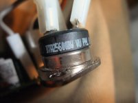
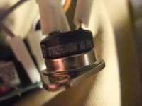
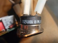
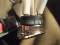
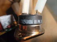
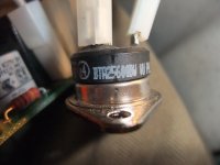
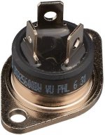
Special TRIAC Version BTA25-600IV BTA25600IV BTA25-600 IV - are there a data sheet ?

From this triac there are no datasheet. Maybe a custom made version - go to the attached images.
This triac was in use in a motor speed controller for large drilling machine without integrated speed control unit.
According datasheet on page 6/12 under
https://4donline.ihs.com/images/Vip...2-1.pdf?hkey=6D3A4C79FDBF58556ACFDE234799DDF0
there are only "B", "BW" and "CW" versions but not "IV" version as you will find in the attached images (except the last image - this shows a BW version).
Thanks for an advice for getting this data sheet.

Attachments

  • DSCF6795.jpg
    DSCF6795.jpg
    980.4 KB · Views: 76
  • DSCF6794.jpg
    DSCF6794.jpg
    983.2 KB · Views: 77
  • DSCF6791.jpg
    DSCF6791.jpg
    979.5 KB · Views: 72
  • DSCF6790.jpg
    DSCF6790.jpg
    988.4 KB · Views: 77
  • DSCF6789.jpg
    DSCF6789.jpg
    977 KB · Views: 82
  • DSCF6787.jpg
    DSCF6787.jpg
    979.4 KB · Views: 59
  • DOC004565916.jpg
    DOC004565916.jpg
    71.8 KB · Views: 56

Next pass amp build

I finished my first build, the ACA, and am really liking this amp.
As a complete diy audio newbie, I found the build fun and satisfying.
So now I am curious about the first watt kits on the DIY site. How do they compare to the ACA? I am powering a pair of ZU soul speakers, 101 db efficient or so, so low power amps seem to be the call.
If I was to try another kit build, which would you suggest?
I am mechanically inclined, but an electronic newbie, so I can build anything, but am a bit challenged with the electronic theory stuff.

KMF

Purifi Millennium crossover help

Hello all,

Whilst being stuck in lockdown, it’s somewhat comforting to have a hobby that keeps me off the streets at night.

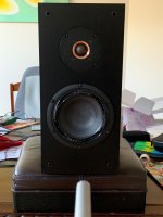
Here’s a passive crossover I developed. My first crossover design.

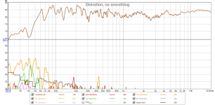
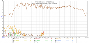
Attached are on-axis and ~45 degrees off axis response, measured at 50cm; 1/24 octave smoothed, also showing distortion components.

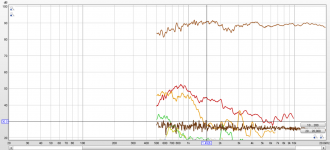
One may notice the dip and peak at 2.5Khz & 4Khz due to tweeter diffraction (position on the baffle, and sharp cabinet edges, but they largely disappear off axis) (See tweeter only measurements)

I’ll be fine tuning this in weeks to come, by experimenting with a lower crossover point to take advantage of the Millennium tweeter- it’s got an underhung voice cool and generous Xmas- I can see why the late Siegfried Linkwitz (RIP) took it all the way down to 1.5Khz (see attached). At the moment it’s about 2.2KHz (+/- 100Hz).

Newer modern tweeters are much more affordable (like SB SDAC29, which I also have on hand) but this one fit my cabinet (110m faceplate)

This cabinet is 21L tuned to 40Hz

Any glaring faults?
Is there too much baffle step compensation?
Are they other measurements I can/should take to optimise the crossover?
Listening tests?
Test tones?
Take it outside and measure at 2-3m?
Ground plane?

Attachments

  • 96A958A1-46EB-45EF-81F3-5FD59E074265.jpeg
    96A958A1-46EB-45EF-81F3-5FD59E074265.jpeg
    328.3 KB · Views: 186
  • 6357C0E3-0A9D-4B9F-ABCB-37BA57EFB5B8.png
    6357C0E3-0A9D-4B9F-ABCB-37BA57EFB5B8.png
    104 KB · Views: 191
  • F19476BA-1F89-4B94-B35F-BE502D75C466.png
    F19476BA-1F89-4B94-B35F-BE502D75C466.png
    108.7 KB · Views: 188
  • D8D4C958-6B23-41BD-9F61-F0D17CD65D53.png
    D8D4C958-6B23-41BD-9F61-F0D17CD65D53.png
    193.3 KB · Views: 194

Full range solution for use with subs

I posted a while back about using the TB W8-1808 with subs in a living room setting. I ended up building a pair of X-LS Encores from GR Research with 2x of their sealed subs. They are fine speakers but in my application I find I have to keep the ports sealed or they sound very boomy. They are also inefficient and I’m interested in either going to active crossover or no crossover.

I’d like to find a new solution using the following notes:
- high efficiency, I’d like to switch to using lower powered amplification
- does not need to go low, I can cross the subs as high as 120hz
- open baffle implementation if possible, or sealed box, rear ports are a problem due to being close to wall
- good EQ solution, analog if possible but open to mini DSP

I’d like to hear some suggestions for good full range drivers and EQ/implementation ideas.

Infinite Baffle BMR + Dolby Atmos

I have a 7.1.4 Dolby Atmos system where all 11 room speakers are KEF HTS2001. They sound fantastic and I shouldn't even really entertain the idea of changing these out. But I've been thinking about what it would be like to have the entire system be composed of DMLs or BMRs.

So, I ordered some exciters and a 3.5" BMR transducer (TEBM65C20F-8) from Parts Express for testing testing purposes. I did some rudimentary DML builds, but was not satisfied with the results, so I put that on pause to try out the BMR. I just cut a hole in a 2x2 ceiling tile and taped the driver in, but OMGoodness! I'm very much liking the sound of it so far.

My question is: has anyone tried a BMR mounted in-wall as infinite-baffle, and what were your results like? I would probably mount the BMRs to a thin panel of plywood and mount that to the wall.

I'm guessing the results would be more pleasing for my system, as there would be no enclosure coloration, no wall reflection, and an increase in low-end (though I wouldn't need them to go down lower than 80Hz). The dispersion from the BMRs would also be very nice, as I'm trying to cover 2 rows of seating, which is difficult to achieve with Dolby Atmos specs, and my room's speaker positioning.

Will I be able to get the desired SPLs for my system (the KEFs are plenty!)? I'd rather do this with 1 transducer per location, as any sort of array would give me undesirable combing.

I'm open to any thoughts and ideas on this. Thanks!

Buffalo-IIIse silent with new spdif source

Hi all,
Please help, having just built this ADC (96/24) AD24QS - Audio Analog to Digital Converter 24 Bit / 192 kHz to run my Retro into my Buffalo-IIIsePro-28, I have no sound, the Spdif input on my B-111 works great with my CD, both the ADC and CD work fine into another DAC (Tascam)With the ADC connected to the Spdif input I get only silence but the lock led lights, the spdif output from the ADC is standard 0.5 VPP @ 75 Ω terminated.
Please help I'm a bit stumped,
Many thanks
Spresto9

E130L in Triode mode

Would like to use E130L in Triode mode with 400-450V on the plate and g2 and -80 to -100V on g1 (should work but I have not tried yet). Should giv at least 25W into a Zpp of 8-10kohm with real good efficience.
Has anybody ever tried a E130L in class B triode connection?
Also other alternatives (like driving both grids or only g2) migth be worth trying as long as the ratings (and I dont mean the published rating for 250V on g2) arent exeded.
Please let me know what you guys think ...

Bigbottle MC only Valve/JFET phonostage Group Buy

Hi all,

This is a bit of a 'test the water' post.

Firebottle and I decided to do a joint project together a little while back. The goal was for me to have a valve phonostage that didn't cost the earth and could hang with the big boys. Alan (Firebottle) suggested I try a DIY project which would keep the cost down and could be built over time when funds were available.

I settled on a board I found online and spent the £9 it cost to buy and get here and I built it. The biggest issue I had was the lack of PSU. This needed building from scratch and pretty soon I was out of my depth and in need of some assistance.

However, this got me thinking. I wanted a DIY phonostage board that was so easy to build that anyone could do it from start to finish, practically unaided.
I searched the internet and there were a few SS ones which might have been a possibility but I wanted valves.

I couldn't find anything that was easy enough so I approached Alan about starting one from scratch. Luckily Alan agreed and we set about the BIGBOTTLE phonostage. I wanted to eliminate the need to build a PSU separately from the main PCB. I don't have the knowledge to build one so I decided that it must be included on the main PCB. Following the same 'paint by numbers' approach as the original DIY phonostage I built.

We took a decent lump of the design from Alan's Vivant phonostage but added a few tweaks. One being the EQ. I wanted a split Eq so that's what we did. The other major difference was MM/MC capability. I didn't want it, so it was made MC only.

We got as far as we could and then needed some help. We had a P2P prototype which I was very pleased with. It has been to a couple of bakeoffs and when compared against some stuff opposition, it was well received. Unfortunately, neither I nor Alan had the ability to convert the practical or theory into a PCB.

We reached out here, on DIYaudio to see if anyone could help. Enter JP.

Jean was willing to help us and took a hand drawn circuit diagram and converted it into a digital version. Next came the mock up PCB layout and on to the final build files.

I sent the files to a company in China and had 5 boards made. I kept one for myself, sent the others out to guinea pigs (lol) and 2 to JP to thank him for his work. I, got to work making mine. I built everything myself, a noob, with limited knowledge. And it worked!!! Alan has tested it and it's a success.

Now up and running and being thoroughly enjoyed daily, I have decided that as soon as JP has finished the final revisions to the design, I will offer a group buy for 10 people. This is going to be a controlled 'roll out' just to see how,

A) Easy it is to build.
B) Get some opinions on performance.

Included with the board will be a BOM. I will also do a Noobs build guide, which should be simple to follow as I have proved lol. The phonostage is MC only.

The first 10 boards will be sold at cost of the board plus postage.

If you are interested, just leave a note on the thread and I'll get in touch.

Pics of the board I built will be added asap.

Boyuu A9 - just purchased the kit !!

Hello everyone - im late to the Boyuu party so it would appear ?
ive built a few amp kits so not entirely clueless but im somewhat holding back on the start of building , so my main pc board would appear different to the one shown on the sale - i appear to be missing the resistor for R301 --- 39/6w - and the other 2 large wire wounds - no substitutes included !!

i have seen many posts here regarding this amp and quite honestly i feel lost now , so many differant views and mods !!

does anyone have a pretty much out the box amp built ??
i also see a few have upped the caps somewhat - 330u on C302 ??
cathode bypass caps
bleed resistors etc etc etc
change the orange drops for example

it would be so helpful if i could simply find an A to Z start to finish page for this thing
most of the insides of these builds all look very differant on these posts , im not a fully fledged electronics engineer so i need to read most stuff in simple terms haha
so can anyone point me in the right direction ?
the basic proven upgrades would also help please , esp for the safety etc
Chris

AC loadline, output impedance and miller effect

I am on my way to design an all dc coupled 300b se amp. I study the material from valvewizard and would like to seek your guidance in drawing the ac loadline for dc coupled stage and the calculation of output impedance.

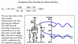
Q1. For drawing the AC loadline,the first pic has clearly explained the calculation of R(ac), which only involve the load resistor and the grid resistor of the next stage. But how about dc coupled stages? I learned from quite a number of dc coupled design and noted that there is no grid resistor in the next stage. So is that the R(ac) is approx. just equal to the load resistor resistance ?


Q2. The second pic shown the output impedance calculation, which involve the load resistor and plate resistance. Does the output impedance affect the frequency response of the next stage through the miller capacitance? For dc coupled stages where there is no grid leak resistor, does the impedance to be involved in calculating the frequency response just equal to the output impedance of the first stage? So for AC coupled stages when grid leak resistor exist in the second stage, does the impedance involved equal to output impedance of first stage in parallel with the grid leak resistor of the second stage (plus grid stopper resistance in series in there is any)?

Attachments

  • ac loadline formula.PNG
    ac loadline formula.PNG
    94.6 KB · Views: 200
  • output impedance.PNG
    output impedance.PNG
    152.8 KB · Views: 200

Biggest factors you've found for enjoyment

Hi all,

Always considering this....what do you think are the biggest factors in getting speakers right, in enjoying tracks?

Here's my list..in a bit of 'remain to change the order of importance state'..

Level freq response. (subject to tonal balance, per following..)
Frequency extension, both high and low, ....with low mattering much more than high....
Max SPL and dynamic headroom.

Tonal balance .
Ability to control track by track tonal balance finely.
(I know this is a bit heretical, but honestly sometimes i think it adds almost as much to enjoyment as all the other stuff combined....which i know can't be true, because the ability to control tonal balance finely comes from all the other factors being being in balance, available for adjustment..)

Smooth pattern transition between driver sections. But so stinking room dependent, it's often hard to appreciate.

Advanced,.... real icing on the cake imo/ime..
Flat phase response.......the effect on transients, timbre, and rhythm.

Tis me best guesses, i guess 🙂

Standing waves in folded qw pipes?

Is there a reasonable effort (maybe even successfully repeated ) which folds the segments of any qw path in a way that creates intervals of the fundamental which are useful? Standing waves as shown (sort of) in the drawing the green pattern doesn’t necessarily peak and valleys much with the blue(fundamental tuning example), but the orange matches up half of the time it’s at its higher frequency. even if this was ‘over welming’ it would be interesting. I had a link to share where some guys in Sweden did something similar, but I think I might have thrown a wrench in that sprocket with the bottom chamber (labeled absorber) and the tapped output after the initial Blue section (200cm2 @ 215-235cm). Too much going on here. It sims well in a variety of ways (with adjustments here/there..

Attachments

  • image.jpg
    image.jpg
    952 KB · Views: 228

6GK5 Musical Machine Help

Hello all,

I'm planing on building the 2007, tube rectified, version of the Musical Machine and I am having a little bit of trouble understanding part of the power supply side of the schematics. I'm pretty new to reading circuit diagrams so if I miss anything silly I'm sorry, still getting the hang of things.

Basically my problem is, that after I got everything straight in my head I actually decided to read the title and saw that the power supply seems to be just for one channel. So my question is: do I duplicate parts of the power supply circuit? The title seems to suggest that everything but the T3 circuit needs to be duplicated for a stereo amp. However looking at images of already built amps makes me think that's not true.

Otherwise I am pretty confident on how this amp goes together, but I'd appreciate any other general advice on parts or how to construct this amp. I'll do some reading around here anyhow and I also have the WayBack Machine to look at Poindexter's old website for parts advice and whatnot.

I'd appreciate any help greatly.

Cheers.

I've attached a copy of the plans I am using.

Attachments

  • 6V6.png
    6V6.png
    49.9 KB · Views: 683

Twist audio signal and ground?

A friend Tom built a 5842 tube > output transformer preamp which I may purchase. Sorry, no schematic yet, but the circuit is simple:

RCA input > 300k series R > 50k pot wiper/pin 2 (pin 1 open, pin 3 shunts to ground) > 5842 tube > Magnequest transformer > RCA output.

Tom did not twist signal and its associated ground anywhere in the chain. I presume performance can only improve if I twist the below pairs of signal and associated ground:
Input > pot
Pot > 5842
5842 > transformer
Transformer > output

Comments welcome.

The MG transformer appears to have only 2 input wires but 3 output wires (black/neutral, orange, yellow/signal); orange is open. Any idea the purpose of the orange wire?

Tom shorted the transformer output black to ground.

What likely happens if I lift the RCA output to ground, IOW only transformer black output > RCA output body? Could I then swap the black/yellow output transformer wires > RCA, thus inverting the signal 180 degrees?

Can this preamp likely convert unbalanced input into balanced output?

TX!

Has anyone tried Soviet tubes on MF X10 V3?

I'm just in the process of purchasing a second hand MF X10-V3 and giving it a go. Of course, as soon as I get something I get curious about what mods are available in case I want to try and make it better. I'm aware of the Rock Grotto capacitor and diode upgrade kit and will likely give that a go after I've had a little while to listen to the X10 V3 in its original state.

I see that the Soviet counterpart to the 6112 Mu-vista tube is the 6N17B-V and possibly the 6N16B-V as an alternative. They can be had real cheap. I'm curious to know if anyone has ever tried either of these old Soviet tubes on their X10-V3 and what results they had. Anybody?

Quick and dirty tapped horn

After spending the better part of a month modelling and building the monstrosity that is 'a simplified transmission line subwoofer' ala Patrick Bateman (thanks again for the guidance John and others), I decided to try out a tapped horn design I had been mulling over for some time.
It's good to compare and contrast, right?
And the reason I did it so soon after finishing one project was because I already had the ingredients for this one 'cut out' from the ruins of the Pipeline. The missus told us this had to go, but in my mind I knew it would return in another way, shape or form. 'Peter would not be told' my art teacher once wrote on my report when I was 10 years old. And she was right.

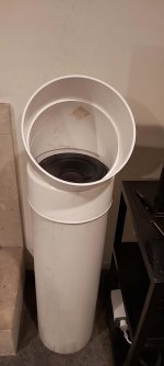
Anyhow, I had this idea for a tapped horn using two pieces of the Pipeline. One is 300mm in diameter or a foot for those still working in the dark ages, and 1m or so in length, which you'd probably call a yard, though we refer to that as the back lawn.

So that's the outer section.

Into that you slide a 1m long 250mm wide second piece of pipe. I'm using PVC here simply because it was to hand. Its original purpose is storm water drain.

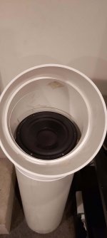
Into the top of the inner section I simply dropped the RSS265HO-44 driver I had available. This literally screws straight in which was completely a fluke. You need to use a gasket of some sort to seal it.

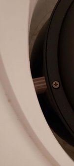
At the bottom end of the outer section you simply block it off with an end cap. But to the inside of that end cap you must add three spacers so that the inner section rests proud of the end cap by an inch or so. I made the gap the same as the distance between the outer wall of the inner tube and the inner wall of the outer tube.

I also inserted three screws into the 1 inch sections of wood so that the inner tube doesn't move around at the bottom end when it's playing.

At the top end, I just made up three wedges of wood to keep the inner tube centred within the outer tube.

Finally, a couple of holes for terminals, and wire up to the driver.

Atop all of this, I had a 30 degree bend that fitted nicely over the top of the outer pipe so it has a hat, and looks a bit more finished.

Ok, admittedly, this isn't the most aesthetic thing I've ever done, but nor is it a complete monstrosity like the plywood TL sub or 3.5m pipeline snake.

I had tried modelling this using HR but really had little idea what I was doing. I did follow Zobsky's Youtube silent movie which was a help and ended up with a tapped horn that had an Fb of 31Hz, but a bit of a droopy response in the middle. The odd thing was when using the LS wizard, it looked pretty good, flattish from about 30Hz to around 100Hz.

Also internal volume was meant to be around 75L and I calculate that my sub plus hat is around 80L, so another complete fluke there.

How does it sound? Well, a bit like classic descriptions of tapped horns. They seem to hit a bit harder in the 35-80Hz zone than designs with which I'm familiar. It's not yet quite as articulate as the big TL monstrosity, but it is only half its size. I had it up and running while watching The Queen's Gambit last night (great show, well worth a look) and the missus either didn't notice the monstrosity was missing or couldn't be bothered commenting on how comely the new sub isn't.

A couple of three pics then.

Attachments

  • Sub standing.jpg
    Sub standing.jpg
    156.5 KB · Views: 313
  • Sub inner.jpg
    Sub inner.jpg
    113.8 KB · Views: 312
  • Sub throat.jpg
    Sub throat.jpg
    141.2 KB · Views: 304

Matlab Audio Output. Need Help

Does any one here know about routing audio in Matlab? I'm running a program that does HRTFs and I can't get audio out any soundcard. The program opens and functions fine, but when loading tells me that it does not know how to output audio on my computer.

It's old software from UC Davis that was last updated in 2012, before Windows 10, which is what I'm using using. Originally it ran on Matlab 5. I am running Matlab R2020b on Windows 10

Two scripts seem to be blocking me, and as I've never before used Matlab, I don't know how to edit the files for my system. check_sound.m runs first and tells me "I'm sorry, I do not know who to output sounds on your operating system"
Code:
% Script to check the OS to see if sound output is possible
% Copyright (C) 2001 The Regents of the University of California

play_sound_flag = 1;

switch computer,
   
case 'PCWIN'                            % MS Windows
   if (exist('wavplay') ~= 2) & (exist('sound') ~= 2),
      play_sound_flag = 0;
      if show_warning,
         fprintf('\n  I''m sorry, but I could not find either wavplay.m\n');
         fprintf('  or sound.m on your MATLAB system.\n');
         fprintf('  You can still use the graphics features,\n');
         fprintf('  but the ''play'' actions will be unavailable.\n\n');
         fprintf('Press any key to continue ... ');
         pause;
         fprintf('\n');
      end;
   end;

case 'LNX86'                             % Linux Intel for Matlab 5
   if exist('sound') ~= 2,
      play_sound_flag = 0;
      if show_warning,
         fprintf('\n  I''m sorry, but I could not find sound.m\n');
         fprintf('  on your MATLAB system.\n');
         fprintf('  You can still use the graphics features,\n');
         fprintf('  but the ''play'' actions will be unavailable.\n\n');
         fprintf('Press any key to continue ... ');
         pause;
         fprintf('\n');
      end;
   end;
   
case 'GLNX86'                            % Linux Intel for Matlab 6 R12
   if exist('sound') ~= 2,
      play_sound_flag = 0;
      if show_warning,
         fprintf('\n  I''m sorry, but I could not find sound.m\n');
         fprintf('  on your MATLAB system.\n');
         fprintf('  You can still use the graphics features,\n');
         fprintf('  but the ''play'' actions will be unavailable.\n\n');
         fprintf('Press any key to continue ... ');
         pause;
         fprintf('\n');
      end;
   end;


otherwise
   play_sound_flag = 0;
   if show_warning,
      fprintf('\n  I''m sorry, I do not know how to output sounds\n');
      fprintf(['  on your operating system -- ' computer '.\n']); 
      fprintf('  You can still use the graphics features,\n');
      fprintf('  but the ''play'' actions will be unavailable.\n\n');
      fprintf('  If you know what MATLAB function to call\n');
      fprintf('  to output stereo sound, do the following:\n');
      fprintf('    1.  Edit the case statement in ''check_sound.m''\n');
      fprintf(['        to add the additional case ''' computer '''.\n']);
      fprintf('    2.  Edit the function ''play_sound_array'' to include\n');
      fprintf('        an appropriate call to your sound output function.\n\n');
      fprintf('Press any key to continue ... ');
      pause
      fprintf('\n');
   end;
end;

It seems that check_sound.m calls play_sound_array.m to do the routing but I have no idea what to change there.

Code:
function play_sound_array(sound_array, fs)
% function play_sound_array(sound_array [fs])
% 
% Plays the sound data at a sampling frequency fs,
% which defaults to fs = 44100.
% Assumes that sound_array(:,1) is the left channel
% and that sound_array(:,2) is the right channel,
% and that the maximum absolute value of the values
% in sound_array is less than 1.
% Copyright (C) 2001 The Regents of the University of California

%% Check for valid arguments

if nargin < 1,
   fprintf('Format: play_sound_array(sound_array [fs])\n');
   return;
end;

if nargin < 2,
   fs = 44100;
end;

num_channels = size(sound_array,2);
if num_channels > 2,
   error('sound_array cannot have more than two channels.');
elseif num_channels == 1,
   sound_array = [sound_array sound_array];
end;


%% Use proper sound output function

switch computer,
   
case 'PCWIN'                                    % MS-windows OS
   vernum = version_number;
   if vernum < 6,
      sound_array = sound_array(:,[2,1]);       % Swap left and right channels for 5.x
   end;
   if exist('wavplay') == 2,
      wavplay(sound_array,fs,'sync');
   elseif exist('sound') == 2,
      sound(sound_array,fs);
   else
      fprintf('\n  This message should not appear.\n');
      fprintf('  Unable to find either wavplay.m or sound.m\n\n');
   end;
   
case 'LNX86'                                    % Linux Intel OS for MATLAB 5.x
   if exist('sound') == 2,
      sound(sound_array,fs);
   else
      fprintf('\n  This message should not appear.\n');
      fprintf('  Unable to find sound.m\n\n');
   end;

case 'GLNX86'                                   % Linux Intel OS for MATLAB 6 R12
   if exist('sound') == 2,
      sound(sound_array,fs);
   else
      fprintf('\n  This message should not appear.\n');
      fprintf('  Unable to find sound.m\n\n');
   end;
   
   %%%  Insert other cases here %%%
   
otherwise                                       % Unknown OS
   fprintf('\n  This message should not appear.\n');
   fprintf('  If playing sound has been enabled,\n');
   fprintf('  you need to edit play_sound_array\n');
   fprintf('  to specify how sound_array is\n');
   fprintf('  to be played.\n');
   
end;
Can anyone help with editing this so that it outputs sound on Windows 10? Default soundcard is fine. If I can choose the USB card, even better.

  • Locked
DIY Cables – Only controversial snake oil or is there more to it?

Hi All,

I’m new to this forum making my first post. I have been somewhat hesitant because after looking around a little bit at old posts I’m surprised how quickly replies get really rude and nasty. I was hoping to find an audio DIY forum to be very open minded community to new brave ideas and different thinking instead I find a lot of Internet trolls lurking in the shadows screaming not-scientific, snake-oil, and worse.

I have been working as an electronics engineer for almost 40 years and have had my share of “science” during my university education and all my years as an R&D engineer. Science is not an absolute truth, science is constantly challenged, reevaluated and changing. “Science” is normally the best understanding and explanations we have available for the moment. If people aren’t willing to be open to new and different thinking the science will not progress and evolve. When you practice R&D engineering every day for a working life you run into many situations where you can’t explain the results with known knowledge. Sometimes these “mysteries” are explained years later due to advancements in new measuring equipment or gained understanding in complex interactions.

The human hearing is a very complex interaction between the pressure waves reaching our body and the brain’s interpretation of the stimulus. In audio we can’t hear everything we can measure and we can’t measure everything we can hear. I’m convinced that we will find different measuring techniques in the future that will quantify things we can’t today. A wise man said that there are 120 different ways to measure an amplifier but we have only been able to come up with the first 20 so far.

The laws of physics are fixed some might say and you can’t change them. Well I say the laws of physics are an attempt to mathematically represent what is going on around us. All these representations are more or less flawed but we are continually tweaking them as we are gaining more insight and understanding.

Legends in the audio field like; Andrew Jones, Nelson Pass, Karl-Heinz Fink, Jürgen Reis all rely on measurements in their work but all of them say that different circuits and components can sound different even if the measurements can’t tell them apart. I highly respect the insight these men and others in the audio field have acquired during lifelong commitment. So all of you Internet trolls screaming snake-oil behind the keyboards that have not paid your duce with your own first hand practical experience on subjects, your input is of no interest to me.

Am I saying there isn’t snake oil in the audio business? In audio, like in any other business, there will be questionable products and people trying to make easy money at the same time as there will also be devoted, honest, hardworking people bringing you their dream product.
Some products will be priced for a small very wealthy group of people which pay more for the exclusiveness rather than for actual performance benefits. If they are paying for snake-oil and are happy, why take that joy from them? It’s not your hard earned money at stake.
“- One man's ceiling is another man's floor” – Paul Simon

I’m hoping to get in touch with people that have experience from making their own DIY power cables. My own experience with power cables for audio equipment is rather limited. I have had the opportunity to listen to a handful of different commercial cables at home in my own HiFi-system. Of them the most expensive was priced to about EUR 600. Some of them didn’t make much of a difference compared to a basic cheap EUR 5 cable, but a few of them presented a clear audible difference. It is without a doubt to me that some power cables can have an impact to the sound, something I hadn’t been able to hear for myself until a few years ago. If not better or worse so at least different. But to my belief no high-end audio power cables can justify a price tag over EUR 9 000 for me. I will rather spend that kind of money on something different. But apparently there are enough people out there buying these products to keep many manufacturers in business. And that is fine with me, but not for me.

I’m looking to make a few good sounding (see note 1) power cables for my own HiFi-system with parts for around EUR 100 / complete cable (or less). Maybe EUR 10-20 per connector and EUR 50-60 for 2 m cable, some heat shrink tubing and possibly some sleeving material. I have plenty of experience making all kinds of everyday cables for industrial applications but I have only put together a few cables for my own HiFi-system.

Have you played around and made several audio power cables and found combinations of connectors and cables that have sounded particularly good to you? Can you describe what in the sound presentation made you a believer in that ‘recipe’? Do you have any listening comparisons to other ‘commercial’ cables?
Please let me know if you are willing to share your experiences and ‘recipes’.
I’m also grateful for tips where to buy the parts.

The possible combinations of different types of cable topologies (shielded, unshielded, braided, twisted, star-quad, etc.), materials and connectors are mind blowing and not doable for one man neither in time or cost so it would be great to build upon previous testing as a starting point.

I could easily buy some high grade Furutech connectors (FI-E50 NCF (R) Schuko EUR 400 + Furutech FI-52 NCF (R) IEC EUR 430) and high grade Furutech bulk cable (DPS-4.1 EUR 500/m) but that would be a total of EUR 1 830; well over my ‘EUR 100 price range’ and I have no experience with Furutech cables so I have no clue if I would like what they do for the sound, if anything. The cheapest Furutech would still be EUR 180 (FI-E11 (Cu) Schuko EUR 45, FI-11 (Cu) IEC EUR 45, cable FP-314 Ag II EUR 45/m). If I use the cheapest Furutech connectors and cable, does it make a big enough difference to the basic cheap EUR 5 to make it worthwhile?

There are so many different manufacturer of good connectors and cables for professional and home audio use, not targeting the high-end Audiophile market, where I hope to find better price/performance ratio. But where to start? How good can I get for EUR 100? Ok, I’m not ruling out pushing the limit to EUR 200 if my ears tell me a significant difference.

I believe, but don’t know for a fact, that when you have good enough parameters for resistance, inductance and capacitance in a well-designed cable there is little to gain with exotic materials and treatments. Any benefit is hardly likely to justify the exponential increasing costs. But I would like to find out for myself, trusting my ears. Where is the sweet spot for price-performance in a DYI power cable? Is it already at EUR 10 or can it be 50, 100 or 200? I’m curious to find out for myself.

Some of you think I’m a fool, that’s your right to do so but it doesn’t make it a fact. Again I like comments from people with their own practical experience. Open your mind to new possibilities, listen, learn and be nice to those that are trying. Looking forward to read about your experiments and experiences.


Note 1:
I’m fully aware that sound impression is highly subjective and what suits some don’t fit others and the environment (EMI/RFI, power grid) the cables work in and what they are connected to makes a difference (some amps, DACs, etc. will be affected more than others by different power cables) but since there is still no way of measuring and quantify some of the differences we still can hear, the ears will have to be the judge.

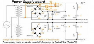
PSA: Chipamp.com snubberized PSU schematic with part numbers

Hi everyone:

I've received so much help from you all on my Chipamp project, that I thought I'd make an (albeit small) contribution back. Here is a pic. of the Chipamp.com PSU with part numbers on top, as well as the LED power light indicator circuit and parts.


Hope this helps someone.

Attachments

  • Chipamp.com PSU Schematic with part numbers.JPG
    Chipamp.com PSU Schematic with part numbers.JPG
    76.5 KB · Views: 948
  • Like
Reactions: bamavette

Programming Environments, what do you use?

I've had a rummage on DIYA and not been able to find anything that can act as a guide on tools for those taking their first steps into programming Arduino or similar devices and wanting to do the usual write, compile, debug, release cycle with the least possible pain.

I have about 30 years experience programming in a variety of languages and on a wide range of systems. But not device programming. Never done it and needed a project to focus my mind on getting started.

So I began looking at devices to program and environments in which to do the programming. I quickly became despondent at the primitive nature of what passed as development tools. They were no better than anything I was using in the early 1990's.

It took time and a lot of swearing, but, eventually I found something that works for me.

So I thought I'd write a single post on what I've decided to use and why. I've focussed on what I liked, rather than A+B comparisons with other products or ways of working. After all, if you're comfortable with something, that's 90% of the battle.

Why not explain what you work with and why...

Circuit Board Building

Does anyone know of a company that will take a drawing of a circuit board and turn that into a real circuit board? None of the PCB companies I have contacted will do that. They all want "Gerber Files" to make the board and I can't make those myself (yes, I have downloaded board design software, but can't make any of them work). So I need to pay a company to convert my drawing into a board.

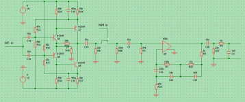
NAD PP2 circuit diagram / schematics

Hi all,

months ago I reverse-engineered an NAD PP-2. Here is the conceptual diagram. Note that abstraction has been made of the actual semiconductors, and that the passives numbering does not match that on the PCB.

It is essentially a PP-1 with an MC headamp added to it. Note the copious use of elcaps for coupling. Also note that total MC gain is about 58dB, as opposed to the promised 60dB.

Attachments

  • nad_pp2.gif
    nad_pp2.gif
    9.6 KB · Views: 5,440

FS: Parallel-86 amplifier boards

I do not need them anymore, have built them for an active speaker system. Still use a pair of these amplifiers in my stereo setup.

280 € incl. EU shipping for the pair of Parallel-86 PCBs
(I guess that is what I have paid for the Bulk foil resistors only)

PSU with 4 x 10.000 uf Nichicon KG capacitors, 35€ each

Attachments

  • PAR-86.jpg
    PAR-86.jpg
    154.6 KB · Views: 168
  • PAR-86_back.jpg
    PAR-86_back.jpg
    132.5 KB · Views: 173

Help :) Trio Kenwood TK-88

I bought a Trio-Kenwood TK-88 model amplifier.
1 channel repaired and replaced power transistors with 2n3055.
This channel gets very hot and doesn't work properly.
I can't find the original transistors 2sd46 these transistors. I want to replace all of the output transistors. I want to portray this old 1967 old man. Which transistors should I choose instead of 2sd46.

Attachments

Projects by fanatics, for fanatics
Get answers and advice for everyone wanting to learn the art of audio.
Join the Community
507,758
Members
7,887,127
Messages

Filter

Forum Statistics

Threads
406,169
Messages
7,887,127
Members
507,758
Latest member
Cindy