I am building a Mesmerize DCB1 with what I believe is the latest PCB from the store. I have downloaded the build notes and schematic but am confused about a couple resistor values.
The schematic is difficult to read because much of the lettering is overlapping. Perhaps I need a different reader? If I could read this more clearly I could decipher the resistor values.
The paired resistors that connect to Q1 and Q3 appear to be 470R on the schematic but the board is marked 68R. The BOM seems to indicate 18R
The BOM indicates 2 1R resistors in the PUS section (R13 and R20 on schematic). Are these 10R on the PCB?
Thanks for all suggestions.
Last edited:
Thanks for those links. They are actually the documents I already have. I got them through the ink in the DIYAudio Store. I can't read that schematic very well - too much overprinting.
I think I have posted this thread in the incorrect forum as most of the Mezmerize activity is in the Pass forum.
I think I have posted this thread in the incorrect forum as most of the Mezmerize activity is in the Pass forum.
Hirscwi the links are very clear to me what app are you using to display the photos on your computer ?
I am building a Mesmerize DCB1 with what I believe is the latest PCB from the store. I have downloaded the build notes and schematic but am confused about a couple resistor values.
The schematic is difficult to read because much of the lettering is overlapping. Perhaps I need a different reader? If I could read this more clearly I could decipher the resistor values.
The paired resistors that connect to Q1 and Q3 appear to be 470R on the schematic but the board is marked 68R. The BOM seems to indicate 18R
The BOM indicates 2 1R resistors in the PUS section (R13 and R20 on schematic). Are these 10R on the PCB?
Thanks for all suggestions.
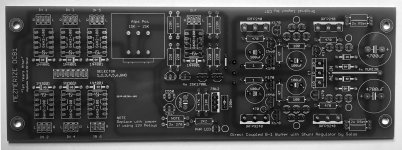
Its 1 on the current board not 10. Also there is 2XRset noted for the suggested 2X18R. Do you have the ten years after board in hand already, or you see it from a store's picture? It could be an older picture. This is how it should be the current one looking.