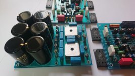
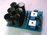
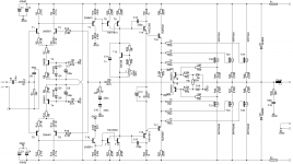
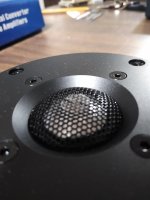
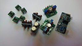
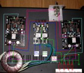
US Amps - Power Supply

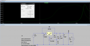
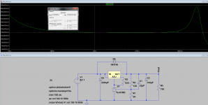
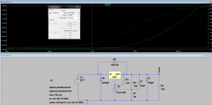
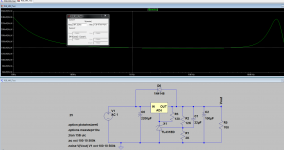
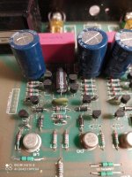
Amp runs fine at B+ under 13.3v. When voltage is increased to about 13.3 volts it goes into protect.

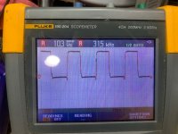
TL494 pin one seems to track the increasing supply voltage. As you increase supply voltage pin 1 will rise to 5v and forces the 494 to shut down when B+ is at 13.3v. At the point of shutting down Pin 3 is at 2v. Pin2 stays at 5v regardless of B+.

Rectifiers are out during this.

  • Poll Poll
KEF LSX, LS50 or Presonus Sceptre 6/8? Or Tannoy? Which to buy?

Which one would be your preference?

  • KEF LS50

    Votes: 7 53.8%
  • KEF LSX

    Votes: 1 7.7%
  • Presonus Sceptre 6

    Votes: 1 7.7%
  • Presonus Sceptre 8

    Votes: 1 7.7%
  • Tannoy (please specify in the thread)

    Votes: 2 15.4%
  • Anything else (please specify in the thread)

    Votes: 1 7.7%

I really like coaxial speakers (since I have first heard Tannoy Dual Concentric studio monitors) and I would like to buy myself a Christmas present to replace my KEF iQ3 speakers in my smaller listening room. I have a subwoofer available and use Chrome Audio for streaming music. I cannot listen too loud in that room.

My budget is 2k USD max. What would be your choice? My boss has a pair of KEF X300A and they are amazing at his desktop - and when playing loud, the sound is still nice and balanced two rooms away (with open doors). I do not need too many bells and whistles, just an audio input analog or digital(optical). The speakers can be even passive, since I have some great amplifiers at hand, too. What would be your recommendation from the list in the subject? Or any other suggestions? And since we are at DIYAudio, I am willing to do improvements after the warranty period is over (LS50 seems to need a little attention to get perfect, for example). Thanks!

Bose Acoustimass 3 humming

We have an Bose Lifestyle 5 & Acoustimass 3 system. I have to say it sounds pretty good in the room, especially for classical music. Great room acoustics and just one cube per channel probably help. Lower bass and some midrange are a bit light.

The Bose has low hours from new. Over the past few years, it rarely has been used because it has a few issues

PROBLEMS
1- Distortion sometimes which overwhelmed any music, particularly on start-up. Some distortion sometimes subsided after listening for a while.

2. No sound from bass module sometimes.

3- Scratchy bass and treble pots.

4- Very dim blue display (although got a bit brighter after a few minutes of use).

Tonight, following some videos and advice of @kevinkr I looked at the Acoustimass 3 module. This seemed easier to open and work on than newer models. There is no service manual and very little information in forums so diagnosis options are quite limited.

BASIC DISASSEMBLY ACOUSTIMASS 3
- remove 3 control knobs
- remove small plastic cover plate and one screw
- pop off big plastic end cover
- remove 3 screws from top board
- remove 6 screws from bottom board / heatsink
- remove 2 wire connectors
- gently tilt top board, heatsink, bottom board; don't rip out the soldiered cables. Don't break the stand-off pins. Caution with heatsinked parts

--> I did not remove the 2 boards from the unit completely as that would likely require desoldiering connectors or removing the transformer underneath.

INSPECTION
- Overall, parts quality and board assembly was excellent. Nichicon caps littered everywhere. The pots were labeled Japan and looked like Alps blue but I didn't look carefully. Board layout and soldier work was very tidy.

- There were some spider webs and dust inside which I quickly cleaned with vaccuum, dust brush, canned air, alcohol.

- Caps looked perfect. Inspected soldier joints with a magnifying glass and frankly everything looked new.

SUSPECTED CAUSES
- There was a lot of spider web stuff bridging a few contacts on the larger wire connector.

- I suppose the power supply caps are always suspect.

- With no factory manual and very little advice on forums, diagnosis work is very limited.

--> I decided to tackle this one step at a time and see the results of the dust/spider web removal. Well, I couldn't resist cleaning the pots also, lol.

REASSEMBLY
- Cleaned and replaced thermal grease
- Followed advice below and elsewhere from @kevinkr
- Don't overtighten the 6 black screws. They can easily strip in the MDF. Overly tight screws will prevent the 1 screw for the white cover from aligning properly.

RESULTS
- 100% distortion for a few minutes, no music heard.

- I power cycled a few times. Distortion declined slowly.

- No distortion after 10 minutes. Sounds perfect.

NEXT STEPS
- I will keep unit unplugged overnight and try this for a few days.

- I will fix the display this week. I think that is just 3 caps to replace in the Lifestyle unit.
To get to the amplifier module there are 8 screws (10? I forget) that have to be removed to remove the bracket the amplifier sits under. Do not remove the plastic plate from the bass module as sealing is crucial and the original gasket should not be reused. When reinstalling tighten the screws by hand only and do not over tighten as it is easy to strip out the flange area as it is only mdf.. If you changed the power transformer you have probably already figured this out.

Watch for twisting in the woofer cable where it comes out of the box , avoid pinching. (Shorts possible - will destroy bass amplifier)

You can pop apart the amplifier module with a large flat blade screw driver if you need to - stick it in the slot and pry gently, so that you are pushing against the plate - do not twist. When you reassemble make sure the heat sink spring clamp is aligned properly with the holes in the board before you put the cover back on. Put end of cover without the aforementioned notch into the notch in the heat sink and press until the notched side locks into the notch on the other side of the heat sink. Be very careful when handling the heatsink not to scratch the area where the devices sit as this is a non-conductive anodyze. You should apply new grease to the devices before reinstalling the board.

Driver IC Question

I don’t own a hot air station .

Wondering what the best way is to remove driver ic’s without a hot air station ?

I don’t wanna damage the board or traces since I can’t just heat up the legs and remove it .

The back tab of the driver ic’s solder to the board .

Any ideas ?

Here is a pic of a new driver ic showing the back

Attachments

  • 0A3ED474-579C-4CA6-AD0D-2597168C24F7.jpg
    0A3ED474-579C-4CA6-AD0D-2597168C24F7.jpg
    1.1 MB · Views: 83

Leaving Long Leads on Film Capacitors

Hi All!

I have a question-- I'm recapping an integrated tube amplifier and I don't have much room when swapping in new coupling capacitors. It looks like I have two choices: (1) seek out small film caps that don't cause me issue; or (2) allow longer lead runs from the caps to their solder points. This is a point-to-point solder framework.

Option 1 leaves me with less than desirable (for me) choices.

Option 2 raises the question of whether it's a bad think to have 2.5" or more leads running from the cap to the point of attachment. I would use tubing or heat shrink to insulate the leads.

Thank you in advance.

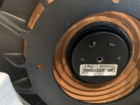
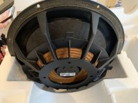
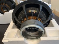
FS: Peerless XLS12 + PR

Hi

I have a Peerless XLS12 subwoofer (830500) and it's passive radiator (830548) for sale.
I've bought them once to make a subwoofer, the subwoofer has been made, but it's never been used and have no other plans with them.

They have not played music for more than 1 hour, are in very good shape and stored in a dry location.

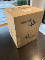
They will be shipped in their original packaging.

Price: around €200?? Not really an idea what these are worth these days.

Attachments

  • IMG_0649 (1) - kopie.jpg
    IMG_0649 (1) - kopie.jpg
    374.5 KB · Views: 506
  • IMG_0650 - kopie.jpg
    IMG_0650 - kopie.jpg
    295 KB · Views: 500
  • IMG_0651 - kopie.jpg
    IMG_0651 - kopie.jpg
    422.6 KB · Views: 499
  • IMG_0652 - kopie.jpg
    IMG_0652 - kopie.jpg
    348.6 KB · Views: 493
  • IMG_0653 (1) - kopie.jpg
    IMG_0653 (1) - kopie.jpg
    326.9 KB · Views: 474
  • IMG_0655 - kopie.jpg
    IMG_0655 - kopie.jpg
    334.4 KB · Views: 192

DSP crossover benchmarking

Are there any standardised tests for evaluating the performance of DSP crossovers?

Besides the obvious tests like dynamic range and noise level, some of the things I'd be interested in would include:

1. Latency
2. Filter accuracy or correctness
3. Low frequency resolution
4. GUI representation vs actual filter for those that come with their own user interface.

I'm thinking of simple tests that one can do to, for instance, compare a Dayton DSP to a MiniDSP.

Should such a standard not exist, what might be a good set of tests?

Supplying power for MiniDSP + icepower box

Hi All,

Bit of a noob question here, perhaps someone can point me to some references to read up on. I've look around a bit already, but having issues finding exactly what I need.

I'd like to pack a miniDSP 2x8 kit and two ICEpower 50ASX's into a box. The question is this: what's the easiest way to supply power to all three with a single power cord? Can I just wire them up to the same power receptacle inside the box? What are the names of any parts that I need?

Cheers!

FS (USA/NJ): Speakers, Sony XA777ES, SCD-1 Remote and Puck, Sherbourn PT-7030, + more

SOLD

Hi all, I need to reduce the collection 🙂 and I am hoping to invest into a DIY speaker build next year so some of this stuff needs to go.


This is best for Local pickup in New Jersey. I can even deliver if relatively close, or meet half way in the Tri-State.

I am asking FAIR eBay market price -10% for this gear.

I prefer a local pickup deal.

Want it shipped?
Total = Price + Shipping+ $10 packaging (for anything that needs boxing)

1) SOLD Sony SACD SCD-XA777ES, Flagship Multichannel Sony SACD player.
- Working great 9/10, I have been listening to it for two weeks now. (Only gave me a problem on one SACD in Multichannel playback, but the CD has scuffs, and my XA9000ES has similar issue with a different SACD that played well on the 777)
- laser was replaced when I got the player in 2013. It hasn't gotten a lot of play time. Was my main player for about a year, it mostly has been a display peace for my SACD player collection.
- Cosmetically 6.5/10. Conservative rating for some scuff and scratches to the Top of the player. Face is perfect, and you cant notice much from a few feet away.
- Includes original box, remote, power cable (maybe manual too, need to check)
- 100% of this sale will be donated to Cystic Fibrosis charity
- $670

2) Sony RM-DS1 Remote for SCD-1 and SCD-777ES flagships.
- I have 3. Choose which one you want.
- Most worn one is 6/10, the keys are definitely a little yellower then the other two.
- 8/10 and 9/10.
- Only sale I see was $200...
- $130, $140, $150, from worst to best

3) Sony SACD SCD-777ES SCD-1 Stabilizer Puck Brass A-4672-800-A
- 6/10. I got it from someone as a spare. I has definitely been rolling around a cabinet and something hit it. I wasn't able to insert it on my SCD-1, there is a tiny nick near the hole. I never got around to file it out... didn't need to.
-$80

4) GIFTED TO FRIEND! NHT SB 2 Bookshelf Speakers.
- 8.5/10
- Beautiful black piano finish, high quality cabinets and paintjob. Just the carcass is worth the $$. Few swirl marks form cleaning. The foam surrounds are whiter on one speaker. They sound great.
- $120? (only pair that sold on eBay was $200)

5) Polk RT25i Bookshelf Speakers
- 8/10. Not much to say, they sound great actually. I'd be glad to keep these or give to a friend 🙂
- $45

6) Definitive Technology BP-2X Surround Speakers
- 7/10. Sound Great, grills are great, drivers are perfect. Some scuffs on top of the cabinets. The laminate is coming off at one corner.
- $120

7) Polk FXi A6 Surround Speakers (These might stay with me but lets see if there is interest)
- 9/10 Looks like new except for some minor scuffs from the speaker stands.
- $180

8) Furman Elite-20 Pfi, Power Factor Correcting Power Conditioner
- 9/10. Pulled from working home theater environment, 20A outlet required.
- $500

9) Pioneer PD-F407 25-Disc CD-File Changer no remote
- 9/10. I cant see anything that stand out, good condition, works great, sounds pretty good, and the CD file system is pretty cool!
- $35

New 10) Sherbourn PT-7030 Surround Processor
- 8/10 conservative rating. Only one scuff on front side panel, can’t see it from a few feet.
- it comes with remote but nothing else.
- came out of a working home theater. Had it hooked up to hdmi and XLR outputs.
- high end preamp!!!
-$375 - I think that’s a steal for this preamp with XLR! Last one Sold for $360+Shipping on eBay and there are some ridiculous listings now for $750+

FIXED AND KEEPING ITBonus: Sony DVP-9000ES w/t remote
- 4/10 cosmetics. It was going to be project so I removed the top cover and sanded to repaint... I never repainted
- 7/10 functional. Correction I ran about 12 SACDs through it and I played all but 2, which it only read the CD layer. So I’d call it functional. Sounded beautiful
- lots of high quality parts in this one, also the face is very nice 8.5/10. Love the design. It will make a great project when you get around to it.
- $65

I think this is it for now.

Pictures are up on the bellow link

Audiophile Gear For Sale - Album on Imgur

Thanks for looking!🙂

Edit: added Shoreborn 7030, update Sony dvp-s9000es

Satori drivers for Troels SBA10, Jeff Bagby Kairos or Adephos

Hello.
Up for sale a SB Acoustics Satori kit to build Troels Gravesen SBA10 or Jeff Bagby Kairos (or Adelphos) 3 way

The drivers are from January 2020.
I was thinking I would build the SBA10 kit, but DIY life is like it is and I switched to The Loudspeaker 2. Now I do not have space, time not the need to build them and will let them go discounted.

I can help with the crossovers for all the kits.

2x Woofer SB23NRX75-6
They are in pristine condition. Like new. One of them absolutely new, only opened for pictures and checking after arrival.
The other one was installed and measured. Perfect condition. No more than sweeps to be measured. 9,9/10 original new condition
Retail Price 149,95 euro each (299,90 both)
Buying a SB Acoustics SB29NRX75-6 woofer? - SoundImports


2x Satori MW16P-8
New in their original boxes. Only opened to be checked. Never connected or measured. 10/10 original new condition
Retail Price 139,95 euro each (279,90 both)
Buying a SB Acoustics MW16P-8 woofer? - SoundImports

2x Satori TW29RN-B
Both have been used in an active system for less than 50 hours. (less than 30 for sure too, but let's stay in the safe side).
One of them is 10/10 working condition and 9,5/10 cosmetic condition. terminals were soldered.
The other one of them has a bolt hole damaged and there is a scratch. It cannot be seen once installed but its there and you have to be some careful tightening the screw, but it's in perfect working condition. 10/10 working condition 8/10 cosmetic condition because the scratch (you can solve it with a permanent marker).
Both tweeters measure almost equal. A small difference of 0,5dB between both of them. Measurements after the text. Green curve belongs to the one with the screw hole damaged.

Retail Price 132,45 euro each (264,90 both)
Buying a SB Acoustics TW29RN-B-8 tweeter? - SoundImports


Total retail price for the kit is 845 euro plus shipping
I will sell all the stuff for 520 euro shipping to EU included.
This price is 30% discounted from the retail price for each driver and it includes the "damaged" satori tweeter FOR FREE. No complaints about that tweeter can be made. It's for free.
If you don't want the tweeters price will be 420 euro + shipping

Paypal fees, if apply, not included.

I'd rather prefer not to split, but I could split the SB29NRX75-6 pair

Countries outside EU, please, ask for shipping.

Tweeter measurements (Green line is the "damaged" one):
An externally hosted image should be here but it was not working when we last tested it.


All the stuff:

An externally hosted image should be here but it was not working when we last tested it.

An externally hosted image should be here but it was not working when we last tested it.

An externally hosted image should be here but it was not working when we last tested it.

An externally hosted image should be here but it was not working when we last tested it.

An externally hosted image should be here but it was not working when we last tested it.

An externally hosted image should be here but it was not working when we last tested it.

An externally hosted image should be here but it was not working when we last tested it.

An externally hosted image should be here but it was not working when we last tested it.

An externally hosted image should be here but it was not working when we last tested it.

An externally hosted image should be here but it was not working when we last tested it.

An externally hosted image should be here but it was not working when we last tested it.

An externally hosted image should be here but it was not working when we last tested it.

An externally hosted image should be here but it was not working when we last tested it.

An externally hosted image should be here but it was not working when we last tested it.

An externally hosted image should be here but it was not working when we last tested it.

An externally hosted image should be here but it was not working when we last tested it.

An externally hosted image should be here but it was not working when we last tested it.

Rockford Fosgate P8002 cycling on/off

Got a RF P8002 in for repair. I opened up and cleaned and requested a schematic from RF this afternoon. PC-4708-B.

After disassembly and cleaning, I noticed R2071 (5 ohm) was popped from its position, where it had some charring on the pcb. This was cleaned and replaced with new. I checked the drivers in circuit and they checked ok. there were no shorts on any of the PS FETs, output FETs.

Amplifier was powered up: (gnd and remote) checked gate drive waveforms and they were good. Applied power with B+, amplifier is trying to start. It draws excessive current, shuts down and immediately restarts and the process repeats cycling until remote is removed.
Lifted D2001, D2002 one at a time and powered up, amplifier repeated cycling. Output FETs for channel 2*** are getting warm.
None of the protection lights are being lit.
I shorted one of the thermistors, and the amp went into thermal protection, where it stopped cycling.

Anyone ever had similar issues with these before?

Attachments

  • IMG_9676.jpg
    IMG_9676.jpg
    89 KB · Views: 85
  • IMG_9675.jpg
    IMG_9675.jpg
    79.4 KB · Views: 93

Sansui AU517, false trigger protector?

Hi. I have this amplifier that when it works at a certain volume, the overload protection is triggered (increased current on the emitter resistors of the output tr's). The point is that it only does it when speakers are connected to the output, in tests with a resistive load of 8 ohms, it never happens, I tested at 100Hz, 1 KHz and 10 KHz, also with music and it went down to 6 ohms and nothing. Could this be normal? The equipment is in excellent condition, as I am very fond of recapping for the simple fact of steel waiting for magic solutions, I do not see corrosion from the famous glue. Attached videos of the failure and the tests. Check the components involved in the protection circuit but I do not find anything out of value. Any ideas?. Thanks in advance.


AU517 fail.mp4 - Google Drive

AU517 test 1-1.mp4 - Google Drive

AU517 test 1-2.mp4 - Google Drive

Digital Filter for a Triamp

I am after some help with a new project; this will probably be my last as I am finding it harder to retain the knowledge.
My existing amp which took me a few years to do is a triamp with active line filters, a microprocessor controlled attenuator with a pic 18f4525 and three pga digipots. There is a single lcd readout for attenuation of each channel. A single optical encoder controls the attenuation of each channel.
The system works great and I want to stay with a triamp but use digital inputs with a digital filter and a three channel attenuator.
I think a digital filter would improve the cut off's between each frequency band compared to what I have in analogue.

I have never done any work with digital filters but my idea is to have a digital input spdif ? or optical ? , then a three stage filter for high, mid and low frequencies followed by attenuation for each channel (so six channels in all allowing for the balance in each pair). I would then need a dac for each pair of channels. Finally the analogue outputs would go to separate stereo amplifiers.
Can anyone point me in the right direction.

I built a high spec amp in March this year which didn't work but with the help from two engineers on this site I got it working great after about 3 weeks so I am really hopeful of some advice here.

Advice on first RH84 build - are these transformers suitable?

Hi all, seeking some guidance with my first (from scratch) tube amp build. Have decided to go with the original RH84 circuit for its simplicity and generally positive feedback.

Have a power and output transformers pulled from an old German (Loewe) console stereo. The original configuration of the amp was single ended, 2 x EF 86 driver tubes into 2 x EL84 outputs.

The power transformer doesn't have a center tap and measures at 310V with resistance is 100ohm. The opts appear to have multi-ohm speakers taps – have attached a pic of one of the opts.

I understand the impedance needed for the opt should be 5k, have been trying to calculate the impedance of the opt primary. Getting a very strange reading: when applying low voltage AC (2-6V) getting approximately 1.5x that on the secondary?

edit - I meant when applying the low AC on the secondary getting about 1.5x on the primary side

Will these be suitable for a RH84 (ver1) build? Assuming I can get the opt measured correctly.

Thanks.

Attachments

  • opt 1.jpg
    opt 1.jpg
    786.6 KB · Views: 378

Isolation transformer "adjustment"

Disclaimer first. I am aware that Im a highly untrained non professional. Any advice given to me may kill me and I will be at fault regardless of the quality of information or misinformation given!!!

So, that off my chest.
The audiophile journey is in full swing...
Oscilloscope- Check.
Auto transformer - Check.
Function generator - (On its way!)
Isolation transformer - Kinda-check...

I wont mention the type of isolation transformer I bought (PM me) but upon opening the case I see two Toroidal transformers stacked on top of each other.

The primary wingdings are colored black and blue.
The secondary are white, black and green.

The chassis ground lug originally had quite a few wires; main power cable ground, isolated outlet's ground, isolated outlets neutrals, and secondary transformer green...

To float my o-scope I disconnected the isolated outlets earth and neutral's from the chassis lug.


At first I left the following connections on the chassis lug, power ground and secondary winding's green wire. I dialed in 20V to the auto transformer, turned on the isolation transformer and low and behold measured 20V from isolated hot to neutral. I than measured hot to chassis and poop.. I had 20V....

So I disconnected the secondary winding green from chassis and it looks like I can float my scope..

To be sure, should the isolated ground's be 100% disconnected from everything ?

Does it sound like I missed anything ?


EDIT...

I said float my scope, i meant float the DUT...
My scope will be plugged directly into house mains on a fully functioning outlet

Any love for the Dayton Audio waveguides? (Parts Express)

In particular, I have a project where I could use the 10" round version.
Dayton Audio H10RW 10" Round Waveguide 1-3/8"- 18 TPI
In that house, there will be NO on-axis sweet spot listening, it will be whole-house sound.

I've been kind of obsessed with the round Dayton waveguides since I feel that's kind of the "purest" horn opening for sound wave generation, which might not really be true but anyway. There is a wall with a big open space behind it, I could stick the waveguide in said wall with a big sensitive woofer(s), in-wall 12" grills I found.
System probably iPad --> AirPort Express --> maybe an EQ* --> amp probably a nice old Onkyo receiver used as a power amp.

* so I don't have to get crazy with the crossover and to level out falling power response at the top end)

LM317+TL431, really?

Been looking at ways to improve the old LM317 and I got the idea to use a TL431 as a reference.

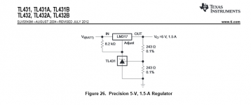
Looking at the TI TL431 datasheet, at page 30 you find the implementation shown in attachment 1.

TL431 is used as a reference at the LM317 ADJ leg, with a 8K2 resistor from input to ADJ leg. TL431 cathode current varies with input voltage.

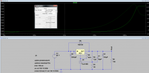
I changed the resistor to 820R, with the TL431 set up for 17.5V OUT and that gives a current through the TL431 of 10.8mA with a 25V input voltage

Attachment 2, 3 and 4 shows the rejection, impedance and noise of this implementation.

So far it seems to work very well, rejection is standard for LM317, the output impedance however, looks way to good to be true, the noise looks fairly standard for a LM317 regulator.

However, what if we move the 820R resistor from the Input to the Output? Well, that I did, and I now reduced it to 120R which gives the same 10.8mA through the TL431. This current would now be fixed at 10.8mA(as fixed as it can be with the 1.25V reference in LM317).

Attachment 5, 6 and 7 shows rejection, impedance and noise of this implementation.

The rejection improvements are substantial, looks like the Lm317 and TL431 rejection is added? Output impedance is one tenth of the datasheet implementation? Noise however, doesn't change much.

Can the improvements in rejection and output impedance really be true or is this some kind of LTSpice fluke?

Any other possible issues with this implementation, like stability issues?

Attachments

  • Datasheet.png
    Datasheet.png
    14.9 KB · Views: 6,182
  • LM317-TL431-Rejection-Datasheet.png
    LM317-TL431-Rejection-Datasheet.png
    61.5 KB · Views: 4,788
  • LM317-TL431-Impedance-Datasheet.png
    LM317-TL431-Impedance-Datasheet.png
    59.7 KB · Views: 4,465
  • LM317-TL431-Noise-Datasheet.png
    LM317-TL431-Noise-Datasheet.png
    54.3 KB · Views: 4,252
  • LM317-TL431-Rejection-Alternative.png
    LM317-TL431-Rejection-Alternative.png
    58.5 KB · Views: 4,175
  • LM317-TL431-Impedance-Alternative.png
    LM317-TL431-Impedance-Alternative.png
    57.1 KB · Views: 1,422
  • LM317-TL431-Noise-Alternative.png
    LM317-TL431-Noise-Alternative.png
    51.2 KB · Views: 1,905

Choice of JFET for cathode CCS

A few years ago I completed a Vacuum State SVP as my backup phono preamp from schematics on the VSE website. This sounds very satisfying (almost as good as my RTP3!), but I would like to lower the line stage gain, as this is too high for my system. I already achieved some reduction from the original version by replacing the 6922 in the voltage amplifier stage with a 5687, and then dropping the cathode resistor from 2K2 to 820 ohms to push the current back to 6mA, but I would like to reduce it further – ideally halving it.

Joe Rasmussen (the original designer of the SLCF line stage in the FVP) suggests a clever way to do this here: this involves increasing the cathode resistor, but then inserting a CCS in parallel with it to restore the net cathode current back to the design value.

100446d1200259535-version-vacuum-fvp5-snoog_fvp_ls-gif


Joe draws a nominal JFET circuit, but doesn’t recommend a specific model of JFET. What combination of parameters would make a device most suitable for this application, given that there is 5V at the cathode, and the CCS needs to pass (say) 3mA? I have plenty of 2SK170bl, 2N5457 and BF245C in my JFET box.

Thanks,

Alex

Advice needed for XO upgrade for Eggleston speaker

Hi,

Making a debut post here.

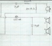
Like to ask if someone could determine the crossover freq for this two way design, Egglestonworks Fontaine Sig SE. Secondly, to confirm those resistors are in parallel, which I think likely so.

I had the non SE version and the manufacturer sent me the schematic for SE version. I can do some simple soldering work but new to crossover design. The manufacturer were not responsive with queries though.

Thanks!

Attachments

  • eggy.jpg
    eggy.jpg
    93.3 KB · Views: 256

Audio Research amp design question

schematic noob here.... 🙂

I'm trying to understand the 'partial cathode coupled' implementation ARC uses. For example, in the VT100, schematics show the primary of the OPT sending signal back to the 2nd grid of the 6550 pentode.

What is the purpose, electrically? Any does this infer a split primary on the OPT? At what turn/percentage?

I'm not trying to replicate this design, necessarily, just understand it.

TIA

Acoustic Preference Power amplifier modules

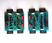
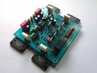
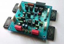
Orig. Acoustic Preference power modules, around 150W/8 Ohms, depending on PSU voltage and current.
Matched 2SA1216/2SC2922 outputs, dual op-amp input. Tested, working. Designed to be mounted flat on heatsink, 4 output transistors plus temp sensor transistor below. PS should be from 2x35 to 2x55V.
Used in A.P. Bravura integrated an mono-block power amps. Never heard a bad word regarding them, soundwise great ..and absolutely reliable.
Depending on hetsink size and PSU..bias adjustable to A class. Input OP-amp currently employed is LME49880, but will work with most dual op-amps, thus you can somewhat tailor the sound. Schematics available for buyer.

Price 120€ for pair.

P.S. Also available one orig. PSU board, with floating ground rectifiers and 60000MFD/63V Mundorf "M-Lytic" capacitors.

Regards

Attachments

  • aa1.jpg
    aa1.jpg
    381.7 KB · Views: 144
  • aa2.jpg
    aa2.jpg
    359.3 KB · Views: 150
  • a1.jpg
    a1.jpg
    401.2 KB · Views: 137
  • a2.jpg
    a2.jpg
    384.2 KB · Views: 145
  • a3.jpg
    a3.jpg
    542.9 KB · Views: 138
  • aa4.jpg
    aa4.jpg
    274.4 KB · Views: 104
  • aa3.jpg
    aa3.jpg
    322.4 KB · Views: 99

Adcom GCD 600 spindle motor always on

I am trying to refurbish an Adcom GCD 600 [TDA1541A] I picked up cheaper than the chip set cost. The loader isn't working but when I put in on the bench and plugged it in the CD spindle motor started running before I powered it on?! I don't understand how it would get power as other functions clearly happen after AC is switched on. I know this is a vintage/nostalgia piece but does anyone know if this is normal for this unit??? Thanks for any ideas!

regards,
Steve

Capacitor fitted to an Interdyn Model 212??

Hi guys.


I'm working on a pair of Interdyn Model 212's.


They'll need refoaming.


I found a single Shizuki 3.3 uF in each enclosure.


They are Shizuki 1,000vdc 2DNO caps.


Would these be electrolytic?
They are red/brown in colour and unusually shaped (none cylindrical)


Refer:


3.3UF 1000VDC 2DN0 CAPACITOR SHIZUKI | RGB Automatyka industrial automation center


cheers


Cliff


FS: Full LX521 Setup with Hypex Ncore

Hello, I´m selling all my audio equipment, I don´t have time anymore to sit, listen and enjoy my music.

List of all I´m selling:
- Lx521 Speakers
- Hypex mpNcore amp 6x125w
- Hypex mpNcore amp 4x250w
- All the cables needed for this system, neutrik connectors and good quality cables.

If the buyer buys everything I´ll include the Minidsp 4x10HD and the plans.

Everything is located in Spain but I could ship to anywhere in Europe.

I´m asking for 2500 euros + shipping.

FS Philips TDA1541A R1 and Philips TDA1541 DAC chip

I have one spare TDA1541 and TDA1541A R1 which I pulled out from Marantz CD40 and Marantz CD65. Both tested working fine.
I like to try TDA1541A S1 and need extra cash. International postage availble. Paypal welcome. Item located in Australia. Each $80 AUD or $60 USD.

Attachments

  • IMG_4885.JPG
    IMG_4885.JPG
    193.5 KB · Views: 376
  • photo_2020-10-30_04-02-07.JPG
    photo_2020-10-30_04-02-07.JPG
    218 KB · Views: 470

Would you change anything ?

Hi ! reading here and there in the forums a fairly common discussion is on how much, keep a design the same, the quality of active and passive components can impact on the general sound.
I am attaching a photo of a channel of a preamp that I have partially destroyed and therefore has no residual commercial value even if it is quite functional
I would like to ask if you spot any parts that could be replaced with others of the same value but of higher quality. I mean diodes and capacitors mostly.
I would keep the original transistors because I would not like to have operating problems
and the resistors saved the feedback one, if I can identify it obviously
A newer version of a preamp for example uses 1N914 (very cheap) instead of the 1N4001 on mine My guess is that the 1N914 is the better part ?
Even ceramic capacitors ... are there any quality series more suitable for audio uses ? the existing look quite cheap
Resistors seem ok.
As I said at the beginning I'm trying to understand if the game is worth the trouble.
I see this also as an opportunity to get familiar with a desoldering pump i have just purchased.
Thanks and best regards, gino

Attachments

  • pre 2.jpg
    pre 2.jpg
    560.5 KB · Views: 271

Troubleshooting Sansui AU-5500 with permanently disabled output

Hello, im currently troubleshooting a Sansui AU-5500 amplifier, it does not output anything, not even noise. I have already made a couple of checks:


-The protection relay RL01 (pag 18 of pdf) does not click and does not enable output;


-Inputted a sinusoid through the tuner input and checked with an oscilloscope the signals right before the protection relay: output is present on both channels, and responds correctly to front panel controls;


-Measured voltage between the two ouputs, it hovers around 20 mV; Measured between both channels outputs and chassis, both measure around 20 mV;


-Checked voltage on R79 which is in series with the relay coil, it measures 0 V meaning the relay is not passing current: checked resistance in circuit of the coil, it measures ~600 ohms. Unless the voltage is taking a strange path the coil does not look like its open, and im guessing it means that the relay is not being told to turn on;


Checked in circuit transistors and diodes listed in section 5.2-2.1 of the manual in the vicinity of the relay with diode mode while in circuit: junctions respond correctly in forward bias with readings of~600 mV except for the weird D15 SV-02 diode which reads higher than the others. In reverse bias they all hover around 1.7 V;


Im currently at a loss on what i should be trying next: i could start pulling out components off and testing them, but the board they are on is huge and seems nested in the amp and a chore to extract. Unfortunately i'm not knowledgeable enough to understand how the protection circuit operates and what voltages and currents should be present on each component, so i cant narrow it down any further without tearing it apart. Any ideas on what could be wrong? Thanks in advance

EDIT: Located faulty TS-01 thermistor reading way too low when cold. Now needing to source a replacement

So what is the down side of a cap multiplier?

Been doing some small improvements to existing low power circuits. Preamp, crossover, DAC etc. Playing with SMPS to reduce ripple and using R-C-R-C filters. Both quite effective and the R-C filter does wonders for reducing current spikes through the rectifier, or if using an SMPS whose tolerance for driving a large C load is suspect in my mind. Getting a 10X reduction in ripple is pretty easy. Nothing to sneeze at. But not quite enough to push the ripple below the noise floor.

So, looking at a capacitance multiplier. Much lower transient current than a bigger cap. Less loss than the large-ish resistors in my RCRC and easily over 100x ripple reduction. 1000x if I give up a little more voltage.

So what is the down side? Cost? No as big caps cost a lot more than transistors even adding a heat sink. Space? Not really. Ability to handle transient loads? Not important if feeding a LDO regulator, but maybe not good for an unregulated power amp supply?

Ear 834 phono pre clone, loud buzzing, newbie

I just traded some speakers for a nice-looking EAR 834P MM phono preamp clone. The trader was upfront about the buzzing noise it has. He tried some grounding fixes, but nada.

All I have done thus far is re-soldered the ground plug wire back to the chassis (he had cut it).

It is a nice sounding and looking unit (other than the buzz!), so I would really like to get this diagnosed and try and fix it.

The trader thinks it is a faulty component. I don't have equipment or training to check caps and resistors, etc, except for my digital multimeter.

Does anyone feel like taking pity on me and try to help me sort this out?

The "brand" is Zero Zone, and they have a schematic for one channel posted on their eBay page:

2020-12-09.png

Is there a full range design that can match or exceed the Kef LS50?

Before anyone jumps on it, yes I know the Kef LS50 is a 2-Way design. I want to use that as my reference though as I really like the sound of it, especially the midrange and detail. I currently have a pair of Kef Q100 bookshelves that I enjoy but want something a bit more in both low-end response and overall clairty. This is why I was initially auditioning the LS50 as a bit of a reference to the next step up.

What I like about the Q100, and very likely the LS50's, is the amazing off axis response. They sound great everywhere in my room including the seat way off to the side. This is one area that I am not willing to downgrade performance in.

I do have a home theater built around Markaudio CHR-70 as ceiling and surround speakers. The are in sealed enclosures that are wall mounted. They sound good for there application not not really a good reference for what I want to achieve in a two-channel system.

I would be interested is any floorstanding enclosures and would like to avoid adding a subwoofer at this time. I experimented with a sub woofer in my room already and didn't like how it integrated. I also like the idea of a full range design for simplicity sake. I've built 2-ways with passive and active crossovers in the past and want something pure and simple. The also means no DSP or room correction. My amplifier is a Yamaha a-s501, which does 85Wx2, and is an "okay" amplifier.

So can I match or exceed a Kef LS50 with a single full range driver? If so which driver and design. Yes I realize that "better" is subjective, but I'd love to hear your opinions.

Cheap AptX HD receivers with decent analog stage

Hi All,

Are there any Bluetooth receivers with AptX HD support, analog output and external antenna (for a longer range) fitting into the USD30-40 budget that are known to produce better analog sound quality than the rest of those in this modest price range? There are sooo many on the market that it's really hard to choose any particular one purely based on their advert descriptions alone. Currently looking at something like this one for instance:
CSR8675 Bluetooth 5.0 RCA Receiver APTX HD RCA Bluetooth Music Audio Wireless Adapter for Car Audio amplifier-in Wireless Adapter from Consumer Electronics on AliExpress

or this one:
262ft/80m Long Range Bluetooth 5.0 Transmitter Receiver 3 in 1 Wireless Audio Adapter Low Latency aptX HD Spdif RCA AUX 3.5mm TV on AliExpress

Unfortunately I have almost no background in radioelectronics and am really bad at soldering, so modding any of them is not an option.

Previously after researching this forum I bought a couple of USB DACs w/o BT to try - DA3 (SA9227+PCM5102A) and an unbranded CM108+4xTDA1387 one - and tbh couldn't complain on their audio quality in my application (a Denon PMA-355UK amp and a pair of hardly known Radiotehnika S90 speakers made by RRR in Riga, Latvia in the 70s-80s, used mostly for outdoors listening in a very quiet place on the nature). So I suppose I need something like those again now, just with CSR8675 or similar for AptX HD.


Many thanks in advance!

Wieliang DAC7 + CM6631 USB Card

Hey all,

I have been very very happy with my Weiliang DAC7 (Wolfson WM8741 based) for years, besting many other DACs along the way.

I have finally decided to try Async USB (to get up to 24 bit 192k) and purchased a CM6631 daughtercard off the bay.

I have USB working, but have two issues:

I have a slight audible hum from this USB connection that was not there via COAX or TOSLINK. The same exact USB extension cable and computer connecting to another DAC via USB has no hum. This DAC7 via USB with different USB cable on a different computer has no hum. Something about this particular computer (or extension cable) and this DAC has hum...

Also, the installation of the 7 pin Daughtercard disables TOSLINK (COAX works fine via original switch). I asked seller about a switch to enable / disable TOSLINK/USB and he is saying switch all 7 pins. I don't think I need to switch all pins... any help on which pins to switch?

Also, before I connected the 7 pin daughtercard, there was a jumper on the empty Weiliang PCB USB connector - I think it was pins 5-6 (I don't remember) that someone advised years ago... what was it for and maybe I need to switch - enable TOSLINK? SPDIF to GND makes no sense...

And yes, I have Googled this already!! Thanks in advance....

Attachments

  • f69f9f2a38068bae.jpg
    f69f9f2a38068bae.jpg
    177.5 KB · Views: 129

Capacitor question?

Hi All.

I will be replacing 2 electrolytic capacitors in a pair of Dali Loudspeakers I have.

There are currently 2 x 22μF caps which I'll be replacing with polypropylene.

The closest my supplier has is 20μF.

If I replace the old caps with 20μF and 2μF caps do I fit these in series and will this deliver the same value?

In series meaning "circuit to 20μF cap, then this to 2μF cap, then to the other end of the circuit?

While at it the existing crossovers have 2 x 10w Bennic 5R6J resistors in each crossover.
Do these deteriorate and is it worth fitting fresh Dayton 10w Audio Grade resistors which I currently have?
Both are of the square profile ceramic casing type.

cheers


Cliff

Harman Kardon TS-7 Amp - Wont come out of standby

Hi All.

I have a Harman Kardon TS7 Active Subwoofer that has recently developed a fault. It sounds good and Id like to fix it, which seems achievable. The circuits are all accessible and most components are descrete. I have found some schematics. I have some electronics background (trained in it years ago) but its a bit beyond my abilities without assistance. Thats where you can help 🙂


Fault: This sub has a auto-standby functionality. It goes into standby automatically if there is no signal. When a signal is applied (I use LFE port) it comes out of standby and the LED turns from orange to blue. This unit never comes out of standby anymore. The status light stays orange. There is an "auto" or "on" switch that should control this standby functionality. "on" should switch the unit on all the time, this does not work. The unit is always in standby. No input sound is amplified.

Diagnosis: I have the circuit boards out and there is no obvious damage, scorching or blown caps etc. I have tested the voltage rails and all show correct voltages. I have noticed that even though the unit undicates its in standby, the speaker is active. I can hear some hiss/noise. The amplifier heatsink also gets warm given some time. The speaker protection relay seems to click on as well. This lets me believe that the output stage is working and the fault its with the input stage. These stages are seperate circuit boards (see photo) with the top being pre and the bottom being power. As a test I disconnected the 'mute' line from pre to power (removed D101) to ensure it wasnt being sent a mute signal. This made no difference so it doesnt seem like its being muted.

Technical Links:
Photo: Link
Schematic Links: Pre, Power, ICs

Additional: There are other known faults that develop with this unit (researched google) and I have applied these fixes. they did not help and dont seem to apply here. Link. and Link

I need some advice on what to test next. I have highlighted some key components. D209 is the external bi-color LED. Clearly this voltage needs to go high/low to reverse the polarity. I dont know which polarity the standby color is. The switch is highlighted, as is the mute line. I feel the issue is in this area as the switch should force the unit out of standby, change the LED and make the mute line either high or low (not sure which). None of this seems to happen.

I have decent tools and multimeter. I dont have a signal generator or the likes. but im savvy and have time. your advice and pointers are appreciated. Thanks in advance.

Tube pre kills HV transformers

Running a single 6SL7 tube with a 200VAC for the high voltage supply, rated for 40mA. I have a bridge rectifier, 100u reservoir cap, and three stages of RC filters (470R + 100u). I've had a couple transformers fail with this setup. I'm assuming an internal open circuit due to thermal stress. There is no AC on the secondary. Is my reservoir cap too big? Should I put a thermistor in series with the reservoir, or perhaps a low value resistor?

Wave guide based DIY recommendations

I just wanted to know if there are any recommended DIY designs that are documented out there that have the following attributes:
Stand Mount/bookshelf suitable for 5-6' out listening from my position
Waveguide Constant Directivity Based Design
Sealed Enclosure (I know this kills efficiency but I much prefer the tight bass)
MTM design (to gain back some of the efficiency and because I've noticed a commonality between 'slam' and 'impact' when dual smaller woofers are employed. This is optional but I believe it's something that would give me what I want.
For music not HT so I'm looking for that elusive vague 'musical' attribute.

I don't need deep response, I will be leveraging an adjustable high pass/low pass and dual M&K 70b subs for low bass.

Not harsh in the highs or overly forward - I don't dislike Klipsch but I'm looking for a dynamic audiophile experience that is not going to cause fatigue after an hour.


I think this will give me:
1. Constant directivity.
2. Good dynamics.
3. Relatively good efficiency considering the sealed design can be slightly offset by the dual drivers as far as efficiency goes.
4. Tight bass due to the sealed enclosure
5. Smooth highs due to the waveguide based design - maybe seos?

Am I off target and have you heard of any designs that would work well with these prioritized 'wants'? Just looking for some guidance on selection and if my suppositions are fair. If DIY sound group had their HT or HTM series in stock with the smaller stand mounted capable models I would likely go there even though none of their wave guide based designs are MTM just to be able to leverage a flat pack versus constructing a cabinet again.

Thanks!

John

B & K 1431 Oscilloscope

Guess what I uncovered while moving the garage? A handy oscilloscope set aside over 12 years ago, a single trace B & K 1431 analog scope.

Cosmetically, it is in near new condition.

Internally, it is suffering from dirty control contacts, and the sweep is free-running: no triggering response.

Can anyone help me with a service manual or schematic for this old soldier??

Its bandwidth will be handy for audio troubleshooting, as the scope display is razor sharp. I wish I still had my BBC Goertz/Metrawatt machine...that was an excellent piece.

If only the years were as kind (the last 12) to this scope, as a bottle of Scotch...:angel:

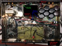
Dynaco ST-70 60 Hz Hum one channel

Helping out a friend with his Dynaco ST-70.
Can't get the hum outta the darn thing.

It was modified before he got it, then it came to me for help.
It had faulty wiring from the mods, which I removed and
redid. The caps were leaking on the SDS board, so those
were all replaced.

Moving Pwr tubes left to right,
Moving Pre amp tubes left to right,
Hum remains in the left channel.

Adding shorting plugs increases hum and it's not on BOTH channels.

Pulling only the left channel 7199 stops the hum.
So, I bought a new board and replaced it.

Somewhere, I read about that heater pin2 to pin2 should have continuity
and pin7 to pin7 should have continuity, but if pin2 to pin7 continuity
exists, this will cause hum. This amp has pin2 to pin7 continuity
everywhere in the amp without any tubes.
Still have hum in the left channel.

I couldn't find it with the scope.
Pic attached.

Tube replacements were also made.
Hum remains in the left channel.


Cheers,

Attachments

  • ST70 Callouts small.jpg
    ST70 Callouts small.jpg
    640.4 KB · Views: 388

MOSFET Amp. Problem

Hi

I have recently designed this amplifier schematic, which is used with a single pair of BJT. In this configuration, the performance is decent.

Anyway, the problem is that I have tried to change outputs to MOSFET and added another 2 pairs in parallel. I have readjusted the BIAS stage, so that I can gain voltage drop required.
In the simulation file (MULTISIM), everything works fine. In reality, the output stage won't work at all.
Input stage and VAS are operating fine, voltage drop across the BIAS transistor can be adjusted. As soon as I connect the mos outputs, acts like a short-circuit and the protection of the power supply kicks in.

Any suggestions, please ? 🙂

Attachments

  • KATHE.png
    KATHE.png
    49 KB · Views: 255

Triggering a relay with S/PDIF?

I would like to use my audio interface to trigger a mains relay, as soon as the audio interface is turned on. Unfortunately, the interface turns on electronically, as opposed to using a mechanical switch. (I need to hold a button for 3 seconds to turn it on. Annoying but c'est la vie).

Therefore, I figured using the S/PDIF output of the audio interface to trigger the mains relay, by cascading two relays: one relay triggered by the S/PDIF output, which in turn triggers the mains relay.

So with the audio interface turned on and nothing playing, I measured the S/PDIF output on the scope and Vmin and Vmax are around -700mV and 500mV respectively, yielding appx. 1.2Vp-p and about 4mV Vac.

Unfortunately, I reckon 4mV is too low for triggering any kind of relay.

For raising the voltage, I looked at level shifting, but I it's problematic because as demonstrated by the Vmin/max, S/PDIF is a differential signal which makes things trickier, and besides, as far as my limited knowledge goes, I think level shifting needs a higher base voltage anyway.

Finally I thought about amplifying the S/PDIF signal with a MOSFET but I've no experience with those and I've no idea how to go about it.

So I'm kinda stuck right now, and would appreciate your help 🙂

Trying to bring an old boom box / radio to life

Hi Folks,

I found an old radio / boom box at work that was going into the bin and I wanted to try and use this for something brand new by replacing the dead components inside with a raspberry pi, touch screen where the cassette was, gpio based amp, and some modern speakers initially before replacing leds/buttons etc. The unit is an Aiwa tpr-901b k linky here:

4 Band Stereo Radio Cassette Recorder Radio Aiwa Co. Ltd.; T

I have a kit list for the project below but the one area I am drawing a blank on is the speakers. I wanted to use car speakers that are low profile and designed to be in a small enclosure, but I was told car speakers are not designed for small enclosure spaces :shrug:.

Any recommendations for speakers on this project?

This is purely for fun and doesn't need to be portable it won't leave the room. I want to do some soldering it has been a long time, I have a 3d printer and will design/print the facia and I can reuse the components for other things.

Kit list:

- Raspberry Pi 4, 2gb OWN
- HiFiBerry Amp2 - 60 watts, works with speakers of 4-8 Ohm impedance and sample rates from 44.1-192kHz (16-32bit). OWN
- 4" Capacitive Touch Screen SCRATCHING_HEAD
- PSU - Mean Well GST60A18 OWN
- Spotify via Volumio distrib OWN
- 2 x 5" speakers SCRATCHING_HEAD

How low can TC9 go in OB/dipole?

Hi,

I am building a LXMini inspired project.
I intend to broaden the overlap of the 6" woofer and full-range TC9 by doing something like this https://www.diyaudio.com/forums/att...um-monopole-dipole-speakers-raw-crossover-png (Pls see this post for more details, https://www.diyaudio.com/forums/mul...sum-monopole-dipole-speakers.html#post4227362).

The linked project has 200Hz and 2KHz as crossovers as below
1) woofer alone below 200Hz,
2) both drivers between 200Hz and 2KHz
3) and only full-range above 2KHz.
Do note that both drivers are at -6dB in the over lap region.

I would like to use 300Hz and 1.2KHz for my project.
It looks like TC9 may not go as low as 300Hz but then its running at -6dB right from 1.2K and lower, so may be it can. How low can I go with TC9?

Thanks and Regards,
WA

Soundstream 405S

Helo all.

Sorry in advance for my bad English.
I come from the Netherlands. 🙂
I would like to know how different the 405s is from the 405.
I have a 405s for repair with the schematic of a 405 next to to it.
for example on the schematic of the 405 D103 to D106 are all the same FED16BT
.
But on the pcb of the 405S D103 and D104 are FEP16CT and D105 and D106 are FEN16CT??
Is there any part list for the pcb of the 405S pcb or a clear drawing of the schematic??
Thank you in advance for thinking along with me!!

Bart.

Audio-gd headphone amplifier kit.

Audio-gd headphone amplifier kit. $200 OBO.

I bought this a while back and never got around to assembling it. The boards are all factory assembled and tested. The included transformer is as specified by Audio-gd. Assembly-connection instructions are included. These boards can also be used as a pre-amplifier with a simple modification.

Two channel headphone amplifier with two amplifier boards and one power suppl board and 1 transformer. The DACT attenuator in the photo is not included but is available for an additional $100.

$150. plus shipping.

Attachments

  • AGD Headphone Amplifier.jpg
    AGD Headphone Amplifier.jpg
    209.6 KB · Views: 258

Best grid traces for 12B4 PCB

12B4_Base.PNG12B4_Base.PNG

I'm teaching myself how to make PC boards, first try is a 12B4 (single triode) simple grounded cathode circuit.

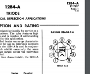
On the 12B4 pins 2 and 7 are both internally connected to the grid. Pin 7 looks like the better candidate for the stopper resistor and connection to the input signal because the engineers left pins 6 and 8 unused, nice. So I was going to have pin 2 then be unused and just soldered to a pad that goes nowhere. Pin 2 sits right between the filament center and and the cathode, and pin 7 has roomy-ness that was my reasoning to use pin 7 for the whole input network stopper, leak, pot and jack.

So my question is... Is it ok you think to leave pin 2 hanging since 2 and 7 are connected and I'll have a stopper on pin 7? Or should I run a trace from 2 to 7 on the PCB as well? Would not running another trace from 2 to 7 just be creating a bigger "antenna" on the whole grid? Perplexed.

UcD400 No Output

I am helping a friend troubleshoot his custom UcD400 based amp which lost one channel of output and now both. I don’t have any experience with these modules short of testing input power and signal, output signal, etc. Fuses look okay and I’m measuring 64vdc out from the power supply, so anything specific I should know about the boards? Maybe they have a trigger that’s gone bad or something?

Thanks for the help!

No problems with Netflix Movies but Tidal Audio Stream Has Issues

Hi,

I recently subscribed to Tidal and about 2 weeks in, the stream started pausing for about a second and then continuing on. I'd say it happens on average once per song. It only does this on my home laptop. Work is fine (more powerful desktop computer). FWIW, work is at a state university network and home is a private internet service provider. However, I can watch Netflix, Youtube, Amazon Prime Video, etc. for hours on end with no probems at home.

Any ideas as to what could be causing this?

Thanks!

Joe

LME49990,LME49713HA,LM49720HA...

Some leftover audio chips and boards.

-LME49990 on DIL8 adapters, 5 pcs.....25€
-LME49713HA, two chips on DIL8 adapters, 3 pcs....30€
-LME 49720HA compact stereo preamp board, gain 1-10, adjustable by trimers. 2pcs....20€
-LME49720 stereo preamp board, fixed gain 10x, on board power stabilization up to 2X50V..10€

Regards

Attachments

  • DSC_0939.JPG
    DSC_0939.JPG
    705.9 KB · Views: 203
Projects by fanatics, for fanatics
Get answers and advice for everyone wanting to learn the art of audio.
Join the Community
507,747
Members
7,886,491
Messages

Filter

Forum Statistics

Threads
406,156
Messages
7,886,491
Members
507,747
Latest member
puma1824