Dr. Geddes' Phase Plug Design

Greetings all,

with the advancement of 3D printers, I have been looking into printing the phase plug disclosed in Dr. Geddes' patent application 2004/0034475.

As I understand it, a Fresnel zone centroid is projected on the diaphragm. However, although the application gives examples for 3, 4, and 5 ring phase plug, as best understood, this is only for a 1 inch driver, as the largest centroid is 0.973.

I am familiar with Fresnel zones pertaining to radio frequency, wherein the calculation of the zones depends on the distance between the source and the destination. As such, I do not understand, how to (re)calcualte for different diameters.

Any insight would be appreciated.

Kindest regards,

M

Deciding Swapping Out Potentiometer Dead Spots

Guitar amp flexwave 65/112 great sounding all channels!

thing is the clean channel reminiscences champagne sparkling signature of the vintage club thirty quartet el84 that slm won favor back in 94 for clean channel.

but for the darnest reason the volume pot misses about the first third of log taper, meaning you can't dial in low volume, & it's loud loud the darlington's final push pull into paper cone.

schematic shows dc blocking ceramic precision caps, it was 2.2mfd, stage to stage dc isolate. but wait, if dc breaks thru the blocking cap, wouldn't it runaway the preamp to dc multiplied? when the pot is dialed past its first third rotation, then the speaker plays, that's at about one pm on the dial. so dc break thru is not occurring if the amp plays the speaker once past first third volume rotation.

I have to decide whether to scissors the flat ribbon cable feeding the topside mounted amp tuner indicator bezel. it's the only way to remove the chassis. It will incur expense buying the coupler to swage onto scissored ends of ribbon cable & we do not know its reliability under cab vibration performance routinely.

ask why the pot does not conduct for the first third? does the input buffer protect from too excessive stompbox signals inciting burn thrus of the pot track? if so how could first third outage be present? I would be disappointed to replace that pot only to realize it will recur later on again. so if it was stompbox abuse, i will repair but if not, it could turn out sketchy whether this burn thru will recur again.

or I could just dial volume past first third & rely upon the electric guitar's master volume to control lower regimes. but you all know the guitar's volume ain't perfect reproducing all the frequencies to our biased ears, especially bridged by a high pass cap to emphasize more highs during lowed volumes.

the bothering question remains, of the digital board & what it is doing, insofar as sensate from the potentiometers, or, does the digital board have nothing to do with the clean channel's volume blindness in the first third?

Attachments

New Ultrasonic cleaner Kickstarter

Came across this;

https://www.kickstarter.com/projects/humminguru/humminguru-all-in-one-ultrasonic-vinyl-record-cleaner/posts

Very interesting to say the least. Joined this forum just to ask you if this way of rotating records has been tried with a standard UC unit? I can imagine one can make 2 3d printed versions with 3 wheels (per side for a 6ltr unit) where you can place the records in. Would be nice if 1 side could be motorized, but rotating can also be achieved with a solex (The moped where you push the engine on the wheel) type of motor...

Just bought myself a 6 liter UC unit and looking into ways to get the records in as efficient as possible.

Regards,

Bas van Lieshout

Peter Blomley Based Amplifier

Hi everyone!

We have recently decided to build an amplifier based off Peter Blomley's original design found in Wireless World:

http://www.keith-snook.info/wireles... to class-B Amplifier Design by P Blomley.pdf

We have faithfully reproduced his circuit schematic while updating components to modern, easy to find variants. Can anyone see any obvious, glaring problems with the attached Gerbers when compared to his schematic found on pg.6 of the linked article?

Many thanks in advance and Merry Christmas!

Attachments

RCA 7094 tetrodes...

Hi,

I have found a pair of RCA 7094 NIB tetrodes in my loft (I bought them years ago as part of a large lot - didn't know they were in there).

I'm a novice in the tube amp stakes - currently just building my first (a nice version of the Bevois Valley amp from Morgan Jones - Sowter transformers arrived yesterday! may be ready for xmas... or maybe not)...

Anyway, do the 7094s have any audio use? Has anyone done anything good with them? As I only have 2, I was wondering if they would make a good SE tube (though I was going to do a 6C33 SE amp next).

Should I just put them on eBay for the radio amateur lot?

Thanks

Nick

Questions about modifying the first Bryston 2B amp

Hello

I have the first Bryston 2B power amps

I have the schematics of the first Bryston 2B, and also the Bryston 2BSST

Those two amplifier do have the sames base for their topologies, but there is somes differences in the schematic who made the Bryston 2BSST sounding much better

Which minimums modifications I would need in the circuit of my old Bryston 2B to made it sound very close to the Bryston 2BSST ?

I include the schematics of those two model power amp section, I found the schematic at that Bryston web site,

http://old.bryston.com/PDF/Manuals/2B_MANUAL.pdf

http://old.bryston.com/PDF/Manuals/2BSST_MANUAL.pdf

Thank

Bye

Gaetan

Attachments

  • Bryston2B ancien.JPG
    Bryston2B ancien.JPG
    415.9 KB · Views: 505
  • Bryston2BSST amp section.JPG
    Bryston2BSST amp section.JPG
    542.8 KB · Views: 326

Concrete Bass Horn Design Question

One of my bucket list items is to build an outdoor stereo system - i.e. a pair of reinforced concrete straight horns.

The tentative driver I’ve selected is a B&C 12NW76
BL = 25.5 Tesla-meters
Xmax = 8 mm
SD = 522 cm^2
MMS = 77 grams
Qts = 0.16


Using a single driver per horn (20 Hz & 160 Hz cutoff frequencies) Hornresp (see above) recommends a 33.5 foot long hyperbolic-exponential horn, with a mouth that’s roughly 16 feet x 16 feet (assuming square mouth). The flair parameter is 1.03, and the horn will supposedly crank out 125 dB down to 20 Hz, without exceeding the 8 mm Xmax. This is good – I can live with that.


But I was tinkering with adding additional drivers (the same B&C 12NW76) – for (qty 5 total) per horn (see above). My thought was a square chamber, with drivers on five of the six sides, all feeding the horn’s throat/chamber. In this configuration (with the same 20 Hz & 160 Hz cutoff frequencies), Hornresp recommends shortening the horn down to 26.7 ft, and increasing the throat area by a factor of five, while keeping the same mouth area - this makes perfect sense to me. What I don’t understand is why the recommended flair parameter changes from 1.03 to 0.93 by simply adding more of the same drivers? Nonetheless, increasing the drivers to (qty 5 total), will increase horn output to about 132 dB, without exceeding the 8 mm Xmax. I can live with that.

Conceptually, am I on the right track here? I've selected a driver with a low Qts, low MMS, and high BL - which is what the old design texts say to do. . . .

200 kHz AB amplifier

Hi guys,

I have to make a 200 kHz 10W AB amplifier with 20 ohm load.
I did a basic 3 stage SMD bipolar transistor audio AMP with Sziklai output stage and +/- 24V supply with no very success. This amp has good band but instable DC operating point, it oscillates from 0V to 0.2/0.8 and sometimes to 1V so the current switch only in a side of the two supply and it doesn't work. When the operating point is stable (very rare) the AMP works but shows a bad parasitic oscillation in the positive half. Probably this is due to the Sziklai output configuration.
I don't know why the DC point is unstable, while in simulation is few mV away from 0V.
Anyway my request is simple, with this frequency as target, should I find a new approach, a new amp configuration? Try a MOS based AMP or a completely new architecture, when can I read something about amplification at that frequency?
With a common audio AMP is not difficult extend band until 200 Khz (with some distortion but I'm not interested in) but I'm finding this DC instability so I don't know if try a new better scheme or change totally.

FAST/WAW Low Crossover Frequency and Full-Range Box Alignment Question

Hi,

I'm building a FAST system with two tapped horn subwoofers and four full-range speakers. The 4 FR speakers are paired up in the same room (a fancy kitchen) pointing at two different listening areas. One toward the cooking area, the other at the table. The FR's will be as small as possible (15-30L), wall mounted, close to the ceiling and pointing down. The crossover is a DSP with up to 48dB/oct slope capability. The TH range is 33Hz-115Hz. The FR's I'm trying to choose between are 8" TB W8-1772 or W8-2145. So I will have to set the XO quite low, which means the FR's will have more to work on in LF. Both FR options roll-off around 90Hz but one is vented with a QB3 alingment, the other is closed. My question is: Should I choose a vented alignment with a port resonance peak at the lower end of the crossed over frequency range of the FR? Ie say the XO freq is 90Hz with a very steep roll-off, could the port resonance be around 100Hz so as to limit cone movement at the lower end to reduce IMD or doppler effects that muddy up the mid and high frequencies? Or would it be ok to just use a closed box?

Best,

Selim

Radio Shack Accurian speaker/amps

Radio Shack is closing out their Accurian Home Plug audio speaker/amps for 19.95. These contain a pair of 2 way speakers (good build quality and very decent sound). One cabinet has a built in 25 watt/channel amplifier similar to the 15 dollar
Accurian power amp discussed elsewhere here.

These can easily be modified by removing and discarding the power amp receiver daughterboard and mounting a pair of phono jacks on the back for audio inputs. They make GREAT powered computer speakers!

You can improve the sound a bit by bypassing the input caps (there are another pair after the volume control) and by replacing the 4558 opamps with TLO72 or 82's (these seem to be the only
opamp upgrades that work well with these). The TLO82's are also sold by Radio Shack for 1.99 each.

Even if you don't use the amp, the speakers alone are worth at least 100.00 for the pair.

Here's the link:

http://www.radioshack.com/product/i...origkw=accurian&kw=accurian&parentPage=search

Yaqin MS-300B SET amp

Does anyone else out there have a Yaqin MS-300B amp? I am very impressed given the price I paid. Of course I ditched the tubes it came with and am using Mullard CV-4024s, Vintage '44 Sylvania JAN-CHS 6SN7GTs, JJ 300Bs and a '59 Soviet/Svetlana 5C3S rectifier. The results? Superb!

And check this - the amp runs my B&G RD50 planar transducers just fine!

I have owned and auditioned a LOT of tube amps over the years but where has this amp been all of my life? 🙂

And it was only $550! (Plus shipping...)

  • Locked
FS: RFT ECC83 Neuhaus - NOS - matched

For Sale NOS, selected/matched tubes RFT ECC83 Neuhaus
From the Spare Parts Tools and Accessories Boxes of medical equipment.

N = "Röhrenwerke Anna Seghers, Neuhaus
RFT = Radio-Funk-Technik

Prod - E. Germany (DDR), early 1960s

Z-grade = industrial quality. They have been tested at the manufacturing plant. that is, they are factory-selected according to the requirements for special equipment.


All tubes was tested in audio amplifier - good balanced, sounds excellent!

sold

payment with PayPal

Best regards!
===========
Olexandr
Kharkiv, UKRAINE
skype: OAA-1974

Hammond 159zl as clc choke

So...I just tried a pair of Hammond 159zl chokes in my f5. 23v rails, dual pair of mosfets. Replaced crc setup. Whoa. Iam liking what I am hearing. It's not placebo.

Do these things (Hammond chokes) break in?

What's the best place or position in the chassis to put them? I could mount the further away from the boards with farther leads or closer to the caps with shorter leads.

Is it advisable to twist the in/out wires on the chokes?

Attachments

  • image.jpg
    image.jpg
    792.9 KB · Views: 1,218

Seeking help. Transformer on my Martin Logan Ascent went out.

Hi

The transformer on my Martin Logan Ascent went dead. So i am in need of a new transformer. My question is: well do i call ML and order a new transformer from them or anyone would know if there is an after market transformer that would work on the Ascent. Since these speaker are so old, im wondering if there is new technology transformer that would work better. Thank you for your times and have a wonderful day.


Trong

Question about TDA2030+BD907/908 amplifier

post-1-1361334786.jpg


Hello


I made this amplifier, and since I don't have testing equipment thus cannot experiment with values of components.

So, I wanna ask what is necessary to lower the input sensitivity, because current input sensitivity is around 470 mV, and I need for input signal around 900-950 mV?
Adding a resistor on signal input or changing the values of R2 and R3?


Thanks

Seas 27TAC/GB, the DXT replacement

Back at it again!

I see very little mentioning of the Seas titan tweeter

H1825-06 27TAC/GB

From what I can see it's a modern replacement to the pretty highly regarded DXT tweeter

H1499-06 27TBCD/GB-DXT

High dispersion, late 80 dB efficiency, metal dome etc. However, this time with power handling to the moon and back. I've read only review I've found of it. He found the two units to be a bit inconsistent with eachother. However, considering it's Seas I would assume it was because if them being early/pre production units. Other than that he was pretty happy with the performance. Does anyone have any thoughts on this tweeter?

Screw threads.

G'day Guys,

I have been taking apart old home theatre amps a bit recently for chassis, heatsinks and power transformers etc.

I have accumulated a huge stash of generic imperial(?) screws that seem to be used across all of the home theatre amps.
IMG_1972.jpg
There is a 7mm m3 screw beside it for scale.

Is anybody able to tell me what this thread is so that I can find a tap for it?

Audison sr1dk in protect!

So I got this audison amp on the bench and it was in protect when customer dropped it off I took the rectifiers out and it powers up fine p.s.drive waves look great do leads me to think it's the output side were the issue is so I pulled the output fets and put the rectifiers back in the amp powered on and has 66vdc & -66vdc rail voltage the voltages are were it's supposed to be on the high and low side output pads but the drive singal looks strange on the scope and i think the AD2K_1 driver module might be the culprit but have never seen or messed with this type of circuit so any advice or help would be greatly appreciated thanks. PIC OF LOWSIDE DRIVE BELOW...

Attachments

  • 20181103_224556.jpg
    20181103_224556.jpg
    998.8 KB · Views: 280

How to set an OPA2134?

Hello, I'm building an amplifier based on the LM4780 chip and I intend to use it in two ways: to amplify the sound of the PC that I use mainly for watching movies and also for listening to music through bluetooth, a tiny MH-M18 card.

In the test I did with the PC directly connected to the amp, the amplifier produces great sound, both in quality and in "quantity": it produces great volume.

But using the bluetooth audio receiver, the sound is very low. Well ... at least in relation to the PC.

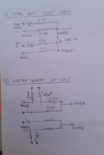
Then I started looking for alternatives and as I have some OPA2134 opamps, I did a test: the bluetooth signal passing through the non-inverting opamp, set in the simplest way there is

Ri = 1kohm (inverting input to ground)
Rf = 10kohm trimpot (between output and inverting input)

Using just the ears and testing with some songs that are in good quality, lowering and increasing the resistance of the trimpot I found a value of 1kohm or a little more ( up to 1k4ohm) that result in a volume, for bluetooth, similar to what I get from the PC. Above that, the sound distorts. But I'm not feeling very comfortable with the measure taken so, by ears, I may be making mistakes like dimensioning the highest and lowest Rf in relation to Ri.

I would like help with the following:

1) Is there a way to take this measure in a more scientific way but without having to purchase an (expensive and, for me, complex) oscilloscope? Some simple resource to know if the signal is being clipped or if it is below what it could be? I thought about generating files of a single frequency using Audacity, for example ...

2) The schemes I am finding, they all create two-stage preamplifiers. However, using only one stage, as I said, and only the ear to reach the maximum without distortion, I have the impression that it works well. In addition, I have seen gain adjustments on the order of 4, 5 or even more times. Why does the scheme I made, which results in a gain of about 2 times, maybe a little more, work well?

3) I have also found schemes that use resistors, from signal to ground, before entering the opamp, to increase the impedance of the preamp input. Is this necessary in my case?

4) I didn't do the test but as not only the volume but also the sound quality improved, I was wondering: if I did the signal that comes from the PC also go through the preamp, wouldn't that also improve the sound on the output? Or the signal from the PC, as it is stronger than the bluetooth, would it get distracted?

Those are, for now, the doubts I have.

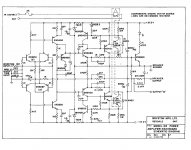
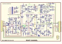
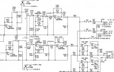
The schemes I am trying to understand with the little knowledge I have so far are mainly those of Rod Elliott (Elliott Sound Products - The Audio Pages (Main Index)), those of Mark Hennessy (Mark's Pages › Home /) but also some others that I have found on the Internet. I have also attended classes that I find on YouTube, for example Gabriel Vinicius' classes (GV ensino - YouTube), which are in Brazilian Portuguese. Even so I confess that I am still in the beginning and therefore I would be grateful if you can help me.

If any information was missing, please ask me.

Thanks.

Question about nx6000

This may or may not be a naive question but here it goes. Hopefully, this is the right subforum to post this to...

I'm interested in building three new bass cabs using three of these: B&C 18DS115 18" Professional Neodymium Subwoofer 8 Ohm

I can only afford three right now but will eventually upgrade to 4.

I have a Behringer nx6000; it has two channels and is capable of handling both 4 and 8 ohm loads.

Will I run into any phase issues by driving two of the cabs wired in parallel for a 4 ohm load, and using the second channel for running the third cab independently as an 8 ohm load? Will phase characteristics stay the same for each channel of an amp when those channels are driving different loads?

QED A240CD lacking bass.

Howdy.

I have a QED A240CD which works OK-ish, but really lacks what I'd call 'full bass'. It does output bass as low as the music source will provide, it's just not loud enough to compete with the rest of the audio spectrum. It's not the speakers or the source used - I have tested for this - it is definitely the amplifier.

I have it on Internet Authority(TM) that electrolytic caps don't last indefinitely -- and the life my amp leads (in the garage) probably won't help their longevity -- could this be the cause of the great bass drought?

Having said that, it's been pretty weedy since I bought it, so maybe it's just a weedy amp.

Thanks in advance for any help or suggestions offered.

Dave.

Speaker Wire for old Full range speaker

This may sound like a super noobie question but I gotta ask, I am in the process of getting an old pair of AD1255/M7 (Philips) in shape. I thought of changing the cables since they are old to new.

Already bought regular copper electrical cables, about 2M to each side. They are around 14 AWG. Will this be good enough or should I use different wires for these speakers....?

Any suggestions will be grately appreciated.

Testing of anechoic box

Hello all.

I have spent some time "ghosting" and learning a lot from the forum and I'd like to ask a question.

I want to simulate free field conditions but don't have access to an anechoic room. I've made a box which I've lined with 25 cm thick foams. When I do a chirp test I basically see nothing after 5ms. Do you think that would be ok to say that we have free field conditions? What other tests would you suggest to doublecheck the sound field in the box?

I'm using the Clio Pocket to do the measurement and I have the Auratone 5C studio monitors in the chamber. Let me know if you need any more information and i can provide.

Thank you very much for your time.

C.A.S. Engineering C-1200 pro. power amp???

Guys, this pro PA amp. landed home, with a complete, missing output stage!...
I've looked everywhere, for even specs on those and, no joy.
This was aparently made in Quebec, Canada, but there are no man. date or address or anything else on the back.
It's a 600WPC rack mount beast, that's built like a tank Destroyer!...
Weights maybe around 60lbs, has forced-fan cooling.
Anybody knows this brand?!?

Brainstorm: DIY Compact High-Fidelity PA

I'm in need of a PA for smaller intimate venues such as weddings and events with 200 people or less. Must be outstanding in sound quality.

About 10yrs ago I purchased a Bose 802 system for such events. It seemed to work well but after some usage I began to realize some of the limitations of the system. I concluded this was more of a mid-fi system that really couldn't produce certain frequencies and didn't have the impact of a true high fidelity system. At times, even at moderate power levels I could hear artifacts in the sound. That was concerning.

I'm starting to line up events for next year and want to improve my sound system. I want to stay away from off-the-shelf systems and build a high fidelity PA using high quality drivers. I also have a personal vocal issue - voice too low. Speakers with good midrange would be helpful.

This PA idea consists of two mid/high tops and a subwoofer. I'd like to tackle the mid/high tops first. I've read thru some forums and have seen some great combinations of drivers. Following are some ideas:

Three-Way (mid/high/mid-bass)
- (x1) BMS 4594 mid/high coax coupled to an Eighteen Sound XT1464 horn
- (x2) Acoustic Elegance TD10M 10-inch drivers

The problem I have with this setup is even tho the AE drivers have some pretty good specs, I don't know if they're made for the rigors of PA use. Their EBP is approx 154 which, for a 10-inch, seems to indicate a pretty strong motor. It also has a high BL. The BMS 4594 is difficult to attain in the US.

Three-Way Coax
- (x1) B&C DCM50 2-inch compression midrange (needs a horn, SEOS?)
- (x2) 10-inch coax drivers with 1-inch high frequency

Coax drivers are new to me, but it seems some select companies are using them for compact PAs (Danley, Fulcrum). Need some input on this.

Attachments

  • high-fidelity-pa.jpg
    high-fidelity-pa.jpg
    36.1 KB · Views: 1,186

Is there a better lamp than the NE5534N???

I have a Bedini 66 preamp which has 6 NE5534N opamps. Is there a more updated or better sounding one in can put in? This is more than 30 years old and I'm thinking there must have been improvements in that time.

Attachments

  • Screenshot_20201222-231016_Samsung Internet.jpg
    Screenshot_20201222-231016_Samsung Internet.jpg
    485.6 KB · Views: 334
  • Screenshot_20201222-231033_Samsung Internet.jpg
    Screenshot_20201222-231033_Samsung Internet.jpg
    408.6 KB · Views: 334
  • Screenshot_20201222-231037_Samsung Internet.jpg
    Screenshot_20201222-231037_Samsung Internet.jpg
    383.6 KB · Views: 333

mixer master section mods, advice needed

hello folks
i am about to implement some mods on the master section of my mixer which could simplify a lot my routing and patching, which are posted below.
I wish to avoid any issues about stage mismatching and signal degradation, so i would like to get your advice about it.
Actually I would like to avoid any active stages if this would be possible since all i/O are line sources/sinks.
thank you in advance

Attachments

  • ctrl.jpg
    ctrl.jpg
    94.4 KB · Views: 135
  • master.png
    master.png
    86.3 KB · Views: 134
  • mods.jpg
    mods.jpg
    111.7 KB · Views: 128

help with ghetto blaster project

to start i don't know if this is the right place to post this and i might be saying incorrect things.links are on the bottom

i want to build a ghetto blaster i want it to sound decent but its more party-fun
bass blasting machine(hip hop, hard rock bass heavy electronic music) then serious audible listening

i found and ordered this $40 amplifier.

2 X 50 WATT 4ohm AA-JA32171 CLASS D AUDIO AMPLIFIER BOARD WITH BLUETOOTH V5.0 & DSP - JAB2V2[753]

it has the Bluetooth and it contains dsp because of this i was thinking of using
a small subwoofer bass reflex/and crossing early to a sealed full range speaker.

since the board is doing the crossover i won't need expensive big coils.
saves room weight and cost.

it will be using 18650 battery's to power the amplifier for a total of 22.2v somewhere between 3000/7000mah depending if i use 6 or 12cells.

other things want to take into consideration most to least important.

1 deep bass for a ghetto blaster
2 small total size
3 louder is better
4 lightweight is better
5 not insanely expensive

for the bass reflex bass i have 2 idea's and concerns

Tang Band W5-1138SMF 5-1/4" Paper Cone Subwoofer Speaker 4 ohm

1 is the amp powerfull enough
2 qts 0.49 a bit high? for bass reflex
3 bit heavy driver for ghetto blaster

i want to use the tb driver because it has such great low bass xmax but there is a lot to say for the wavecore


Wavecor SW118WA01 4-1/2" Balanced Drive Paper Cone Subwoofer 4 Ohm
in comparison to the tb

1 smaller cabinet
2 qts 0.39
3 half the weight

what do you think
or should i just skip the idea and do a traditional 2 way or full range speaker.

thanks for all the help and i will be keeping updates on the project.

Tang Band W5-1138SMF 5-1/4" Paper Cone Subwoofer Speaker
SW118WA01_02
WONDOM | STORE

quad 520 help - noise when turning off

Hi,


i have a quad 520 power amp and recently moved - now when i turn off i get a farting crackle noise on the right channel, instead of the usual pop.
Plays fine.


I looked inside and the T2A fuse on the right channel has blown.
I've ordered a new fuse so will see what happens.
Just wondering what people think - could it be a one off or will it blow again? (i guess i'll find out when the fuses arrive)


i have a multimeter but not a lot of knowledge in this area.
I can't see anything else untoward on the inside.

thanks

Pioneer DVD screen or digitizer bad?

Anyone with any experience with touchscreen components, please advise me... I have a Pioneer AVH-P5000DVD head unit that works fine, just the screen has some visual damage. I am unsure whether the actual LCD screen, or the touchscreen digitizer is where the damage is. The touchscreen works fine and the screen shows the picture in all areas. I can purchase the digitizer for $50, but the screen is hundreds of dollars new and I will likely not bother to repair it. I am posting some pics, so if anyone has seen this type of damage before, please advise me as to what exactly is damaged

Attachments

  • IMG_20201223_014142.jpg
    IMG_20201223_014142.jpg
    980.8 KB · Views: 70
  • IMG_20201223_014152.jpg
    IMG_20201223_014152.jpg
    826.1 KB · Views: 80
  • IMG_20201223_014731.jpg
    IMG_20201223_014731.jpg
    942.9 KB · Views: 63
  • IMG_20201223_014219.jpg
    IMG_20201223_014219.jpg
    981.3 KB · Views: 65

(All else held equal) Is CD best for 16/44.1 ?

This query may be best suited to original Philips/Sony scientists who were involved with the CD project. But anyone can chime in.

A vlogger on YouTube claims that the latest CD players are the best-sounding CD players of the ~40-year history of the format.

Whether the vlogger REALLY believes that and/or is saying that (because of $$ support from manufs b/c that's what pays the bills) is anyone's guess.

Part of the basis of the vlogger's claim is the assumption that a huge amount of R&D was done for the Red Book format to assure smooth data transmission. We assume Sony/Philips included controlled listening tests.

But say you had your favourite DAC chip ... OS or NOS is unimportant as is the output section. What is important is the decoder chip, CD transport, SSD/HDD .. all that stuff before the DAC chip. And you can pick your favourite CD transport and file transport. And for file playback, let's stick with 16/44.1 WAV.

So ... all held equal ... which will measure best? Which will sound best?

Couple of interesting things from the video:
--Quite a significant number of high-end manufs that are STILL making and releasing new CD or optical-disc payback models. (Audiolab, CEC, Roksan, etc. etc.)
--Stats on new CD sales (year by year, and total format history).
• Physical album shipments in the U.S. 2019 | Statista
So, yeah ... the CD format can be milked for quite a while ... especially 2nd hand.

Audio Research D115

I purchased a used AUDIO Research D115. I turned it on once, the green leds flickered and I heard a faint crackle through my speakers. Now the amp will not power up at all. I checked the tubes and determined that they are fine. The fuses are also fine. I examined the inside of the amplifier and everything looks fine. Any help would be greatly appreciated, thank you!

fighter jet sound amplitude vs airbourne and groundbourne decibels sound

bit of a quandry are the same decibels and sound frequencies experienced from below a fighter jet going overhead as been above the fighter jet.


lets say it was flying 1000 feet above ground level


would or what could be heard 1000 feet above its flying level


to what is and can be measured at ground level


please move to appropiate section mods thankyou

Build #2 of my amplifier

I have completed the new version of my amplifier which is a class AB, 300 watts per channel, and has all plans available at


GitHub - profdc9/PowerAmpAudio: Power Amplifier based on Michael Chua's C300 amplifier


including schematics, gerbers, drill patterns, a grounding diagram, and instructions. There is the amplifier, a soft start board, a power conditioning board, and a board for converting between balanced and unbalanced audio signals. Version 3 can use either spade or screw terminal connectors for the power, better suppression of ground loops, and speaker connections and has three options for frequency compensation. The latest build is shown below in a 4U rack mount case:


V3-amplifier.jpg


Visit the github site and you can download all of the plans using the download link and star it if you like it.

Philips MRO PT8 preamplifier

Good evening DIY Audio,

my new preamp is just finished and i'm really happy with the results.
Some years ago i had 2x EL82 poweramp monoblocks but although good sounding they were not to remain. One of the monoblocks was rebuild to a 6C45PP SPUD-amp and the remaining chassis/monoblock was the basis for the new preamp.

This new preamp is in essence a Kimmel-/Mu-stage preamp with a Philips MRO PT8 as "bottom tube" (voltage amplifier) and a Amperex 8608 penthode as "upper tube".
The volume control are a couple of step attenuators from scrapped (Rohde & Schwarz) measuring equipment. Each channel has 2 attenuators:
- one of the attenuators has 6 steps of 10 dB;
- the other attenuator has 9 steps of 1 dB and 5 steps of 0,2 dB.
More than enough options.

The power supply is completely in a separate housing but fixed to the audio-housing. One of the connecting tubes is hollow; here is the cabling between power supply and audio part of the chassis.

In one of the pictures you can see the PT8 preamp next to the 6C45PP SPUD-amp. Same chassis but the one with the bigger tubes is the preamp…..fun.

You don't see MRO PT8's in abundance but many manufacturers produced equivalents as these repeater triodes were quite common decades ago. The 4 volt 0,25 filament already indicates that it will take some time to heat up. Correct ! It functions within half an hour; it performs in a hour.
STC 3A/107A, Standard Electric 4019A, WE 101L and Philips 4609 are equivalents.

What does this preamp bring: amazing soundstage ! My trusty 20 years old Gryphon XT-MC has seen many competition last years but always came out as the better performer. Till now.
From sweetspot to sweetroom ?!

Although i have some PT8's in store it's time to look for 4019A's, 3A/107A's, WE101L's......so if you have those i'm interested.

Keep showing all your interesting projects on this forum. So many interesting items to see.
Regards,
Reinout

Attachments

  • DSCN1789.JPG
    DSCN1789.JPG
    549.8 KB · Views: 597
  • DSCN1774.JPG
    DSCN1774.JPG
    472.3 KB · Views: 569
  • DSCN1877.JPG
    DSCN1877.JPG
    555 KB · Views: 524
  • DSCN1746.JPG
    DSCN1746.JPG
    529.8 KB · Views: 526
  • DSCN1778.JPG
    DSCN1778.JPG
    698.8 KB · Views: 540
  • DSCN1873.JPG
    DSCN1873.JPG
    487.3 KB · Views: 327
  • DSCN1861.JPG
    DSCN1861.JPG
    455 KB · Views: 284
  • DSCN1887.JPG
    DSCN1887.JPG
    513.7 KB · Views: 311
  • DSCN1817.JPG
    DSCN1817.JPG
    340.8 KB · Views: 304

My First Design & Build Project

Hi,

I have recently started my first design & build project where I am aiming to produce a portable multi-way loudspeaker. Considering I have a background in mechanical engineering, I plan to use simulation software (ANSYS) to verify and optimise my enclosure design before fabrication using additive manufacturing methods.

At this very moment, I have a few conceptual enclosure designs that all use following Dayton Audio drivers:

  • ND105*4 4" Aluminum Cone Midbass Driver 4 Ohm
  • NHP25Ti-4 1" Titanium Dome High Power Neodymium Tweeter
    4 Ohm (x2)

I have also considered using the following passive radiator in one of the designs:

  • DMA80-PR 3" DMA Series Passive Radiator (x2)

Would anyone be able to help me identify an appropriate crossover circuit that I can buy for this driver arrangement? (Any other advice regarding my project would be greatly appreciated, this is my first project 🙂)

Full Range Driver Suggestion

Hello guys,
I want to build my first own speaker and thought a Full Range Driver would be a good place to start since I would not have to design complex crossovers but rather only a notch filter/ baffle step.

I wanted to ask for some advice on what driver could fit my needs.
Currently I own a Sonos One which Sound I like but I hear so much music I thought upgrading would be a good idea.
I mostly listen to HipHop / Electronic but also Indie-Rock, if you want to know artists / albums to get a better idea let me know.
My room is 15m² big which would be around 160 ft².
Hearing distance is around 3-4m since the speakers will be under / besides my TV and my bed is that far away.

I read about some Tang Band Drivers and am really interested in the W8-2145 although I mostly read it is good for vocals / instrumentals which is why I think it might not fit my needs, what do you guys thinks? Does anyone of you own it and could report about it?

Some Questions for aleph building

Hello,

I am planning to build aleph amp and preamp more ( I have tries some already), in order to make it better, I have some doubts.

First for Aleph P1.7, Does it need separate power supply for each channel ( service manual show one power supply feed both channel). Does it be worthwhile to do that? compare to more cost added.

Second point, for mosfet matching, beside the current used. I curious that, do we need regulate power supply to do this job or not? Does a little voltage swing affect the Vgs value that we can measure from each mosfet?
I have tried to match the mosfet following the procedure in passdiy site, but still some deviation between each matched. Do I miss some point to make it perfect match.

Thank you for Answer
Tanwa

App Output-DC-Detection with LED Indicator

Hi everyone!

For my SSR project I have found a simple circuit to provide Amp Output DC indication (here in the forum).

902044d1608053646-app-output-dc-detection-led-indicator-dc-detectors-png


Looking at this circuit I'm wondering if the follwong simplification would not have the exact same functionality while taking less space on a PCB (which is one of the reasons even thinking about simplification 🙄🙂 )

Thanks for educating me!
Regards,
Winfried


BTW: In my implementation the AC-off detection is done separately and therefore not of interest in this particular case.

Attachments

  • DC Detectors.png
    DC Detectors.png
    113.3 KB · Views: 507

Class A operation estimate based on the measurement of electrical energy consumption

Hello, by varying a 1KHz RMS sine wave Vout into an 8 ohm resistive load, is it correct that the measured current consumption "IM" from the mains (stable at 230VAC) will be constant until the amplifier changes class A to class AB?

At that point (when the mains current starts to increase) I should understand how much power is delivered in class A before switching to class AB (whose maximum power output will be when the THD approaches 1%)
by making:

Power in Class A = Vout^2 /8 @IM constant
Total Power (in Class A+AB) = Vout^2 /8 @THD < 1%

Class A operation ratio %= Power in Class A / Total Power * 100

In general how should be the IM curve for a Class A/AB amplifier?

Can Motor-Run Capacitors be used in a cross-over?

I am looking to repair my Beovox loudspeaker cross-over, and need 15uf (schema) or 16 uF (actual used in the speaker) . The existing caps are bi-polar.

Of course I find several MKP capacitors, 15 uF is easy to find.

but I also stumbled upon MKP motor run capacitors. They have a low equivalent resistance; they have a low loss factor; and they come in 16 uF.
In fact, they can handle quite a current. (Even though I don't need power at my listening level, under 80 dB).

My straightforward question is: can I used these in a cross-over? With their low resistance - at least in the woofer section.

(I use them in my tube amplifier, works great)

Universal/informal battery charger

You sometimes need to charge the odd element or pack in isolation, because the charging circuit is lost, broken or else.

A lab supply is ideally suited to the task: set the voltage to the fully charged voltage, adjust the current to C/5, C/10 or any suitable value and that's it.

Unfortunately, you need to mobilize a lab supply for several hours, which is not practical or efficient.
In my case, the supplies are part of my "instruments wall", meaning I have to power my whole lab as well.

20~30 years ago, I built a very simple and crude implement: a 120V wall-wart equipped with 3 series capacitors acting as ballast.
It delivered a current of 15, 50, 120mA at up to 24V and had damping components to suppress ferromagnetic resonance.
It was efficient, because of the reactive ballasts, but other than that it was pretty rudimentary.
I had used X-type Rifa capacitors, because I thought they were SOTA, reliable as a Volvo.
I was wrong: recently, one of the caps failed and began to smoulder, ending up in a short and frying the transformer which fortunately ended the show.
It very nearly caught fire though. Beware of Rifa caps!!

Now, I have built a successor, less efficient but more versatile and sophisticated: it charges 1 to 15 NiMh elements at a current selectable from 2mA to 500mA.
It is fully protected against overvoltages and reversals, and does not discharge the battery when unplugged from the mains.
It has no great originality, but it works well and has been built, tried and tested

attachment.php


It is fitted with the usual multiplug combo lifted from a universal adapters, and also alligator clips for the rest

attachment.php


The voltage is calibrated directly in N° of elements (1.45V)

attachment.php


It is possible to reverse the polarity

attachment.php


The construction is relatively compact

attachment.php


attachment.php


attachment.php

Attachments

  • UniCharg0.png
    UniCharg0.png
    32.9 KB · Views: 220
  • UniCharg1.jpg
    UniCharg1.jpg
    248.8 KB · Views: 212
  • UniCharg2.jpg
    UniCharg2.jpg
    210.4 KB · Views: 192
  • UniCharg3.jpg
    UniCharg3.jpg
    227.6 KB · Views: 206
  • UniCharg4.jpg
    UniCharg4.jpg
    283.8 KB · Views: 213
  • UniCharg5.jpg
    UniCharg5.jpg
    344.6 KB · Views: 203
  • UniCharg6.jpg
    UniCharg6.jpg
    309.7 KB · Views: 203

Talk me out of it: MTM using two Xt Mini Centre channels

So I've been toying with the idea of trying another coaxial driver when I heard (somewhere on this forum)
about the Tannoy XT Mini, which is a 4" Dual Concentric driver with a 0.75" tweeter that can reach upto
50ish KHZ! Apparently that driver has amazing imaging capabilities probably do to the smaller mid being
able to go higher and my guess is using a shallower slope.


Using my DEQX, I've been playing around with different drivers up top and really liked the TB 0.5" Silk tweeter. There's just something very nice to my ears about having that effortless top octave without the

beaminess of the larger tweeters. Even my KEF LS50's as much as I love them could have a little more air

in the top end.


And then I saw these on the TANNOY site:
tannoy-revolution-xt-c-4-center-channel-medium-oak.jpg


Now I've been reading about some of the drawbacks on MTM's, but I've read that alot of

that can be ameliorated using a coaxial in the center because of the lower crossover.


The XT mini centre comes off the plinth and I'll bet I could turn it sideways and use it like an MTM

configuration. Are there any drawbacks to this? I cant see why this speaker would perform much different than a left or right main. Here's the specs:


Drive Units

Dual Concentric™ High Frequency 20 mm (0.79") Linear PEI dome with Torus Ogive WaveGuide and Omnimagnet technology
Dual Concentric™ Low Frequency 100 mm (4”) multi-fibre paper 35 mm (1.38”) voice coil
Bass Driver

Crossover

Crossover Frequency 2.8 kHz
Crossover Type Passive low loss 2nd order low pass, 1st order high pass

Construction

7.9 kg (17.5 lbs)
Enclosure Type Rear ported reflex
Volume 7.6 l (0.27 cu. ft.)
Dimensions H x W x D<br />(incl. plinth) 176.9 x 450 x 205.6 mm
Weight
Recommended Amplifier Power<br />(Watts RMS)25 - 120
Continuous Power Handling<br />(Watts Peak RMS) 60
Peak Power Handling (Watts) 240
Sensitivity (2.83 Volts @ 1m) 89 dB
Nominal Impedance (Ohms) 8
Frequency Response (-6dB) 62 Hz - 52 kHz

rega planet 2000

Rega Planet 2000 cd player

Hi everyone, so on this fateful day I managed to break the connector
that connect the laser unit motherboard to the mainboard by pulling
too hard trying to release the ribbon cable. I knew I am in big time trouble instantly when I saw that thing broken. I hope
whatever soldering skill I learned can help for the repair.
So now my job is to look for a replacement for that connector. I've googled
many places but can't find anything like it. 23 pins, 1mm pitch, female.
I know this is a very old unit manufactured in the late nineties but if anyone
knows the source of this connector please let me know I'll be whole heartly
thankful for that..

3-Way crossover beginner question

What I'm trying to design is 3-way speaker system, 1 tweeter 8 ohms, 1 mid 8 ohms, and 1 low 8 ohms, all passing through a Parts Express 3-way passive crossover. That load going to the amp is still going to be 8 ohms correct?

I'm getting hung up on whether or not I need to calculate anything between the speakers and the amp if I'm separating the signal to three separate frequency ranges with the cross over.

Help a newbie!! Thanks and Happy Holidays!

-Ben

Stereo SuperGainClone project build

I designed a SuperGainClone PCB which is available at the github project


GitHub - profdc9/SuperGainClone: A stereo layout of Bob Cordell's Super Gain Clone amplifier.


it includes schematics and gerbers. It is based on Bob Cordell's Super Gain Clone amplifier on the LM3886. It fits DC rectifier and two stereo channels on a small 100 by 117 mm PCB. You can see the build below with a 200 VA, 25 V toroidal transformer, fitting in a small box approximation 225 by 180 mm in footprint:


SuperGainClone-build.jpg


Check out the project and you can download it with the download button, and star it if you like it.

Replacing BJT with lateral MOSFET

I have an amplifier project I have been working on for several months now and have already built two versions of. I've attached the most recent schematic to this message. The amplifier is working fine and uses MJL3821A/MJL1302A BJTs as the power output transistors.


My friend and I who have been working on this project want to try something different, and use the ECW20N20 and ECW20P20 lateral MOSFETs to see if the bandwidth/slew rate/distortion might be improved using the MOSFETs.


I have a few questions about what changes:


1. In the schematic below, there is a bias servo that limits the quiescent current as the transistors heat and their emitter-base voltage decreases. In a class AB configuration with MOSFETs, the voltage between the gates of the N and P channel MOSFETs determines the quiescent current, which is in turn dependent on the threshold voltages of the MOSFETs. The ECW20N20 drain current increases with temperature below a certain Vgs (0.6 V, see attached graph) and decreases with temperature above this voltage, for example. Therefore the drain current will self-limit if the threshold voltage is above 0.6 V. Do I need to worry about the region below 0.6 V, or could I just set the bias to a fixed voltage and allow the transistor drain current to self-regulate with temperature?


ecw20n20-idvgs.png


2. When paralleling BJTs, one can use base stopper resistors to suppress oscillations, or sometimes omit them. When paralleling MOSFETs, one must use gate resistors or otherwise the two joined gates could oscillate with the capacitance of the gates resonating with the series inductance of the connection between them. How does one choose the value of these gate resistors? If they are too small, they do not suppress oscillation, and if they are too large the gates charge too slowly. Is it approximately sqrt(L/C) with L being the inductance of the trace and C between the series capacitance of the two gates? Because one of the major benefits of using a MOSFET vs BJT is only needing to charge the gate rather than continuously draw current, keeping this resistance to a minimum is key to making the transistor slew fast in voltage.


3. Similarly, how big should source resistors be on the lateral MOSFETs? They should in theory share current because the drain current should drop as the transistor heats, however, this depends on good thermal sinking between the devices and the devices being above the 0.6 volt threshold.


4. Are there any breakdown or failure mechanisms that occur with lateral MOSFETs that are not commonly known? They are supposed to be very rugged as far as I have heard, supposedly being superior to BJTs in that they do not have secondary breakdown and a negative transconductance with temperature. Are they really worth it compared to the BJTs I have already used MJL3281A/MJL1302A?


Thanks for any answers.

Attachments

What comes out of each side of a ‘compound horn’?

If we build a bass horn/pipe(TL), using one driver or an isobaric ‘single’ with a qw pipe of 240 cm on the ‘front’ output and ~80 cm off the rear output.. But, we fold the 240cm into a 120/120cm so it spits out in the region that a 40/40cm fold on rear output would. Since we must facilitate the driver entry with a CSA / Sd adapter, there should be a decent seperation between the open end of the pipes... driver suited for a 200 cm2 CSA(plus brief adapter) on both ends. all set, all good.

Now, with a tone generator, we start at 200 hz and work our way down in frequency thru the fundamental length of the ‘80cm’ pipe where ‘normally’ it would start increasingly unloading and excursion in a vented below tuning results in likely damage if abused in this way. but?


say it just keeps going? what is emitted from the short pipe all the way down to the other sides fundamental of the long side ?

I dont exactly know, but ive been trying to capture it and any null that creeps on thru that region in small similar or large and not so obvious tapped versions? lost a few things down long folded paths (vents) trying to hard so i better ask instead(dats and a cell phone slo mo video yet to be retrieved 😱
Projects by fanatics, for fanatics
Get answers and advice for everyone wanting to learn the art of audio.
Join the Community
507,758
Members
7,887,117
Messages

Filter

Forum Statistics

Threads
406,169
Messages
7,887,117
Members
507,758
Latest member
Cindy