So I got this audison amp on the bench and it was in protect when customer dropped it off I took the rectifiers out and it powers up fine p.s.drive waves look great do leads me to think it's the output side were the issue is so I pulled the output fets and put the rectifiers back in the amp powered on and has 66vdc & -66vdc rail voltage the voltages are were it's supposed to be on the high and low side output pads but the drive singal looks strange on the scope and i think the AD2K_1 driver module might be the culprit but have never seen or messed with this type of circuit so any advice or help would be greatly appreciated thanks. PIC OF LOWSIDE DRIVE BELOW...
Attachments
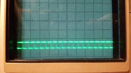
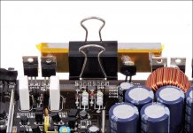
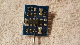
The signal was rolling almost and I'm kinda new with the scope. But when the output fets are put back in the amp goes into protect I pulled the output fets that amp powers on fine I believe the problem may be coming from the output module card on this amp it's labeled AD2K there is two optocouplers FOD3180 and on the other side there is a lm319 ic so I downloaded the datasheet for the optocouplers and the lm319 so I probed the output and VCC legs of the lm319 then I probed the legs of the optocouplers and I get -65vdc on almost every leg so I'm a little puzzled.
The scope wasn't triggering. Try adjusting the trigger level.
The signal seems to be about right for the low side drive (for what I'm assuming that you have in this amp). The output side of the opto-coupler will have one terminal (5) on the negative rail. Terminal 8 will be about 15-18v above the negative rail. The output terminals (6 and 7) will swing between the voltage on terminals 5 and 8.
The signal seems to be about right for the low side drive (for what I'm assuming that you have in this amp). The output side of the opto-coupler will have one terminal (5) on the negative rail. Terminal 8 will be about 15-18v above the negative rail. The output terminals (6 and 7) will swing between the voltage on terminals 5 and 8.
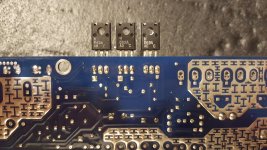
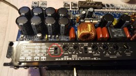
I have also noticed that the three smaller transistors in the photo below two run extremely hot and the last one on the right is barely warm. I took some voltages readings of them with black probe on terminal ground red to each leg and this is what i found from left to right. 1st 649A transistor.(hot)
G. -11.52vdc
D. -25.85vdc
S. -12.28
2nd 669A transistor.(hot)
G. 11.98vdc
D. 26.24vdc
S. 12.67
3rd 669A transistor.(lukewarm)
G. -50.81vdc
D. -37.09vdc
S. -50.17vdc
PIC BELOW...
G. -11.52vdc
D. -25.85vdc
S. -12.28
2nd 669A transistor.(hot)
G. 11.98vdc
D. 26.24vdc
S. 12.67
3rd 669A transistor.(lukewarm)
G. -50.81vdc
D. -37.09vdc
S. -50.17vdc
PIC BELOW...
Attachments

Ok Perry great to know ima go to bed but tomorrow after work I'll take another look at the voltages on the optocouplers because most pins were negative rail or close but I'm think there mite have been one or two pins that were different but I thought it was strange I was getting almost the same reading on almost every pin.. so thanks for making some sense of it for me.
Post #5:
The first two are voltage regulators. Voltage regulators get hot. In many amps, they will fail within seconds if not tightly clamped to a heatsink. If you have to operate the amp for extended periods, you can make a temporary heatsink using a piece of insulated aluminum stock. You can use the insulators from the amp if you don't have Kapton tape.
#6:
Don't let the probe slip. The optos will be instantly damaged.
There are several techs from Europe who have information on the electromedia (sp) amps. Hopefully one of them will be able to definitively answer your questions.
Attachments
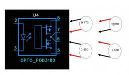
I just did the test again with a working opto and it gives the results I wrote. My opinion is the variation depends on the type of multimeter and therefore on the current that delivers on red and black probe
I never seen it before but i think is ok, because usually broken otpo fails some other values.
I never seen it before but i think is ok, because usually broken otpo fails some other values.
Ok I understand anything else I can check on this amp that might find the issue? Could the regulators be my problem I feel there working but not forsure I'm getting the correct voltages do you know what each should be outputting? Pic of the regulators below
Attachments
There's a sot-23 2D pnp transistor on the output module and I can't get any readings from it in diode mode or ohms it reads open in all ways is that normal because i know on the hifonics output modules i get good readings on the 2D transistors.
PIC BELOW
PIC BELOW
Attachments
Bad news it was working fine for maybe 30 mins then it started humming with audio or no audio and as soon as you hit play on the track it goes in protect then powers back on. Could this be (op amps)?? Sorry for any inconvenience im still a noob to this site and I'm learning as I go..
When I put RCA's in the hissing gets worse also starts crackling and popping randomly but when you hit play on the track it violently pops and amp kicks off same if I flip the amp chain mode switch it will violently pop with or without RCA's..
With black Probe on Main ground and red probe on the RCA ground sleeves it reads 0.140vdc
Voltage on speaker terminals is 0.050vdc when I shut amp off it drops down to 0.0
With black Probe on Main ground and red probe on the RCA ground sleeves it reads 0.140vdc
Voltage on speaker terminals is 0.050vdc when I shut amp off it drops down to 0.0
Attachments
Last edited:
- Status
- This old topic is closed. If you want to reopen this topic, contact a moderator using the "Report Post" button.
- Home
- General Interest
- Car Audio
- Audison sr1dk in protect!