Ok this Is what I got on the op amps black probe on the op amps ground pin and red on the output pins which are pins 1&7. So most of them read the same which is
11.6_11.7vdc on pins 1&7. But on ic#4 pin1 read 1.2vdc and pin7 11.8vdc. An on ic#5 pin1 read 11.7vdc and pin7 22.8vdc an it would drop down to 13.2vdc and climb back up to 22.8vdc over and over!..
11.6_11.7vdc on pins 1&7. But on ic#4 pin1 read 1.2vdc and pin7 11.8vdc. An on ic#5 pin1 read 11.7vdc and pin7 22.8vdc an it would drop down to 13.2vdc and climb back up to 22.8vdc over and over!..
Repost the voltages using the RCA shield or the main ground as the reference (black probe). Post in a vertical column. You can copy and paste these. Use a separate column for each IC.
Pin 1:
Pin 2:
Pin 3:
Pin 4:
Pin 5:
Pin 6:
Pin 7:
Pin 8:
Pin 1:
Pin 2:
Pin 3:
Pin 4:
Pin 5:
Pin 6:
Pin 7:
Pin 8:
Pin 1:
Pin 2:
Pin 3:
Pin 4:
Pin 5:
Pin 6:
Pin 7:
Pin 8:
Pin 1:
Pin 2:
Pin 3:
Pin 4:
Pin 5:
Pin 6:
Pin 7:
Pin 8:
Ok I will get on it there is 10 op amps so it might take me alil bit to write them all down. But ill post back asap..
Thanks perry
Thanks perry
Ok here you go.
Ic#4
Pin 1: this pin kept changing from -10.2 then to 0.140
Pin 2: 1.006 then 0.140
Pin 3: 0.140
Pin 4: -11.62
Pin 5: 12.01
Pin 6: 0.156
Pin 7: 0.156
Pin 8: 0.156
Ic#5
Pin 1: 0.141
Pin 2: 0.141
Pin 3: 0.141
Pin 4: -11.87
Pin 5: 12.28
Pin 6: 3.7-4.8 kept changing
Pin 7: 0.9-4.0 kept changing
Pin 8:0.9-2.9 kept changing
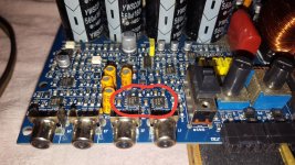
PIC BELOW of the Ic,s in question.
Ic#4
Pin 1: this pin kept changing from -10.2 then to 0.140
Pin 2: 1.006 then 0.140
Pin 3: 0.140
Pin 4: -11.62
Pin 5: 12.01
Pin 6: 0.156
Pin 7: 0.156
Pin 8: 0.156
Ic#5
Pin 1: 0.141
Pin 2: 0.141
Pin 3: 0.141
Pin 4: -11.87
Pin 5: 12.28
Pin 6: 3.7-4.8 kept changing
Pin 7: 0.9-4.0 kept changing
Pin 8:0.9-2.9 kept changing
PIC BELOW of the Ic,s in question.
Attachments
You're missing the +15 supply voltage on pin 8. Is the +15 regulator working?
+15 is generic for the low voltage supply. It could be 10-15v.
+15 is generic for the low voltage supply. It could be 10-15v.
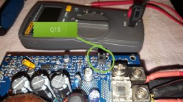
Ok I check all regulators this is what i got.
Q15.
1.11.82
2.11.80
3.11.12
Q57
1.-11.45
2.-25.22
3.-12.22
Q58
1.11.91
2.25.66
3.12.60
Q59
1.-48.64
2.-35.80
3.-47.98
1=E 2=C 3=B..
Q15.
1.11.82
2.11.80
3.11.12
Q57
1.-11.45
2.-25.22
3.-12.22
Q58
1.11.91
2.25.66
3.12.60
Q59
1.-48.64
2.-35.80
3.-47.98
1=E 2=C 3=B..
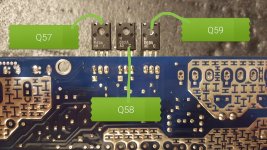
It looks like Q57/58 are the regulators. If Q57 emitter connects to pin 4 of the op-amps. Find the break between the Q58 emitter and pin 8 of the op-amps.
I think you confused pin 5 to pin 8....check again
°_____
| 1 8 |
| 2 7 |
| 3 6 |
| 4 5 |
--------
°_____
| 1 8 |
| 2 7 |
| 3 6 |
| 4 5 |
--------
Ok I here's the op amps in the correct order.
Ic#4.
Pin 1: -10.30
Pin 2: 1.018
Pin 3: 0.139
Pin 4: -11.74
Pin 5: 0.156
Pin 6: 0.156
Pin 7: 0.156
Pin 8: 12.14
Ic#5
Pin 1: 0.140
Pin 2: 0.140
Pin 3: 0.140
Pin 4: -11.70
Pin 5: 11.34
Pin 6: 11.38
Pin 7: 2.4-6.4
Pin 8:12.19
Ic#4.
Pin 1: -10.30
Pin 2: 1.018
Pin 3: 0.139
Pin 4: -11.74
Pin 5: 0.156
Pin 6: 0.156
Pin 7: 0.156
Pin 8: 12.14
Ic#5
Pin 1: 0.140
Pin 2: 0.140
Pin 3: 0.140
Pin 4: -11.70
Pin 5: 11.34
Pin 6: 11.38
Pin 7: 2.4-6.4
Pin 8:12.19
But I think I have a bigger problem so I probed the output pads to see if my voltages were still were they were supposed to be and now there off!
Low side fets.
G.-64.45
D.0.010
S.-58.00
High side gets.
G.0.011
D.64.25
S.5.43
Black probe was on center tap I believe!
Low side fets.
G.-64.45
D.0.010
S.-58.00
High side gets.
G.0.011
D.64.25
S.5.43
Black probe was on center tap I believe!
- Home
- General Interest
- Car Audio
- Audison sr1dk in protect!