10 pin connector

What's this called and how can I find a replacement. Note the missing leg that's why I have to replace it, the bottom pins are thinner than the top ones. I prefer Farnell. Many thanks. Ruler is in cm/mm and I know I placed it wrong but you might figure the distance between the pins anyway.

Attachments

  • P1030828.JPG
    P1030828.JPG
    611 KB · Views: 190
  • P1030829.JPG
    P1030829.JPG
    413.8 KB · Views: 182

Roon remote with volume knob

Hi,

I have really been enjoying using Roon, its current running through an integrated amp, so volume control is easy, but soon I will switch back to some Hypex amps and would rather be able to control the volume though a device, tablet.

I wonder if there is a nice hardware solution for having a physical volume knob, the microsoft one can work with any bluetooth connection, and with the Surface line can bring up a custom display.

RE1XEdV

Apparenty


Would this work, thinking a cheap amazon fire and one of these could make for a really pretty interface?

A simple but effective way to suppress room reflections while measuring

Good evening

While playing with different crossover filters: :scratch1:

https://www.diyaudio.com/forums/multi-way/340978-vintage-style-sealed-enclosure-3-loudspeaker-dome-tweeters.html

ARTA-OT.jpg
ARTA-burst decay-"naked" loudspeaker

ARTA-MT.jpg
ARTA-carpet

MT.jpg

ARTA-MBT.jpg
ARTA-bathroom carpet

MBT.jpg

ARTA-MCK.jpg
ARTA-couch cushion/pillow

MCK.jpg

And finally:

FR-HI-MCk.png
Holmimpulse-FR using 24db LR-filters

Looks like I now can, before room reflections/modes are kicking in, with this insulation, make reliable measurements down to 70 Hz in my living room.

Best regards and stay healthy

FS: Scanspeak, B&C, Peerless, Dayton

Paypal only, CONUS only. Prices are for each driver lot. Prices include shipping.

(2) Dayton Esoteric ES180TiA-8: taken out of box for measurements in a defunct project $190
(2) Dayton AMT2-4: NIB $100
(1) Dayton RS28A-4: NIB $50 SOLD
(2) Peerless 832873 Nomex 5" woofers: lightly used $100
(1) Peerless 830872 Nomex 4" midrange: lightly used $50 SOLD
(2) Peerless 831882 Exclusive Nomex 5" woofers: NIB $120 SOLD
(2) Peerless 830883 Exclusive Nomex 6" woofers: NIB $120 SOLD
(2) Peerless 830884 Exclusive Nomex 8" woofers: NIB $150
(2) Scanspeak Discovery 18W/4434G00 18cm woofers: NIB $100
(9) Fountek FR88EX 3" woofers: lightly used $225
(2) Fountek NeoCD1.0: NIB $80 SOLD
(2) B&C 8CXN51 8" coaxials: one lightly used for auditioning, the other NIB $400 SOLD

Dead Dayton Audio SA240-B subwoofer plate amp

Bought a Dayton Audio SA240-B subwoofer kit from Parts Express probably around 2009. When it worked it was okay, but for some reason I now cannot get anything out of it. It drives a Dayton Audio 15" DCS380-4 subwoofer rated at 4 ohms. I understand that these plate amps had a problem with the auto power on feature. Could anybody point me to perhaps schematics or some where I could start to see if I can get this fixed. I would rather see if I could fix this rather than have to buy a new plate amp. Any help or ideas would be greatly appreciated. Finally talked my wife into letting me get a new A/V receiver after many years...its a long story. But I am missing the bottom end that a subwoofer can add to movies. Newbie here but glad to be here. Thanks.😀

Help with MAX492 Amplifier Chip?

Hi Guys - You all were awesome in helping me understand the difference between AGND and DGN in my recent post on the MAX541 DAC here and I got that working well.

As mentioned at the end of that thread, I need to amplify the DAC's output signal to a reasonable line level. When I hookup the output of the MAX541 DAC to a 3.5mm jack, and then connect that to typical computer speakers, the output is clearly quieter than from a typical consumer device like my phone or laptop.

I have this logic analyzer that also will analyze analog signals. As shown below, I'm reading a max peak-to-peak output from the DAC of about 0.12 volts:

DACexport.png

I purchased a MAX492 amplifier chip in hopes to use it to amplify the DAC output to a normal line level. Datasheet here.

I have it configured exactly as shown in the "typical operating circuit" from the datasheet (but not using IN2+/- and OUT2 since I only have a single input signal):

circuit.JPG

This appears to boost the signal to 0.23 volts:

MAX492Oscilliscope.png

But I really need to boost it a good bit higher. A Google search tells me typical headphone jack outputs are around +/- 2.0 volts.

I've read through the MAX492 datasheet and it's not clear to me what I can do to increase the amplification. Any help would be most appreciated. Thank you.

Tapping Bits

Hi All;

Saw these at Home Depot. Had some 10-32 holes to tap in an aluminum heat sink. The set contains 8-32/10-24/10-24/10-32 and 1/4-20. I bought them to try. They are made for use with an impact driver; not sure why anyone would use an impact driver to tap holes. I don’t have one. I drilled an undersized pilot hole using my drill press and then followed up with a cordless reversible drill.

It was the least painful hole tapping I have ever done. Used WD-40 as a cutting fluid and these bits will tap a hole in 5/16 aluminum in one go. Tried it with the 8-32 bit and it worked like a charm. The only reversing was to get the tap out when I was done. Pretty cool tool. These worked pretty well. Too bad there’s no 6-32 or 4-40 taps.

Attachments

  • 0C09E28D-18FE-4DF8-9DEE-9EA4EDA29923.jpg
    0C09E28D-18FE-4DF8-9DEE-9EA4EDA29923.jpg
    844 KB · Views: 280

Which preamp for Amp Camp?

Hi Guys, newbie here.

I’m in the process of constructing a pair of Amp Camp amps because I’ve been without decent audio equipment for far too long. Cost is a big consideration right now, so I’m ordering and building as my budget allows. I’m currently waiting for custom PCB’s that I designed in KiCad and the heatsinks are on their way too. Next will be the actual components and case.

In the meantime I’m considering my options w.r.t. a preamp. So far, I’ve looked at the following:
Objective2 Headphone preamp
Bride of Zen
Doug Self preamp
New PASS preamp
All are relatively complicated (and maybe too expensive) as a first build. Therefore I’m leaning towards a quick and dirty solution for now. Maybe something simple off eBay, like the LME49720+Shield+ALPS Potentiometer stereo preamplifier kit.

Or the DIY X29F Single-ended DC Class A preamplifier kit stereo preamp kit.

What really bothers me is that I don’t know what specs to look for in a preamp. I have read that an output of about 3V is required to drive the ACA’s to full power, but very few spec sheets give output voltage. I’ve seen the O2, B1 and BOZ being recommended for use with the Amp Camps.

This is really a difficult decision for me. Obviously, I need something that would do the new amps justice, but without breaking the bank or being a major construction project.

Any guidance and/or recommendations will be appreciated.

ECL805 parallel SET build

Hi,
i am in the process with a new build, currently breadboarding and experimenting.

The main idea is to build a simple, secure SE-amplifier paralleling the two triodes power-pentode sections of the ECL805 and devise a driver with the two triodes. My design goals are to maximise the bandwidth my OPT permits, NFB≤12db, mainly H2 and H3 below 0.1% for normal listening.

An externally hosted image should be here but it was not working when we last tested it.

Using the paint_kit tool (thanks to Dmitry) and trioded curves i found (thanks to Tom Schlangen) I set a working point that seems to fulfil my requirements. More to come when i am actually testing this later.
A german guy did a similar amplifierTrioden-SE mit der Roehre PCL805 von Frank Kneifel but it has to much NFB and the 2-stage driver is not to my liking. Anyway, it will provide a reference i intend to improve.

I will document my progress here, starting with the PSU, and will continue to design the power stage next.

Greetings, Harald

eBay board recommendations

No doubt this is anathema to many, but here goes.
Having completed a lm3875 project, thanks to the kind help of some members of this forum, I'm back asking for suggestions for a new project.
I had the good luck of landing some ADS l810s, which need a 4ohm stable amp and a bit more power than my past project will put out. I'm currently using a Sony TA-AX500, but it too is (supposedly) not designed to handle 4 ohm loads, and so I'm nervous whenever I turn up the volume. It's a lovely amp, and I don't want to burn it up!

So, I'm thinking of building a new amp with my leftover 250VA 30-0-30 toroidal transformer. I have a heatsink, and can build an enclosure. I'm not sure if I have the time or skills or money to build an amp from scratch, so I'm wondering if any of you can recommend a set of eBay boards that would match my transformer and my speakers well. Also, I'm on a pretty restrictive budget.

For example, has anyone had any luck with the LJM Quad 405, or the LJM Accuphase e210 clone?

Thanks!

notch filter for distortion measurement

This notch circuit is intended for distortion measurements, where the fundamental is 1.0 kHz, and the harmonics (2kHz,3kHz, etc) are very faint. In such a case, the fundamental may overload the measuring devices, so a notch circuit is introduced to reduce its amplitude, and allow the harmonics to be measured.

Here is a notch circuit (in attachment) that gives a sharp null for a not-so-great-Q inductor. The values shown will null 1 KHz, to better than 100db, and negligible insertion loss if less than 1 octave below or more than 1 octave above notch.

The circuit is derived from How to calculate LC notch filter - online calculator written by M.Shenberg, from an article in "Radio" magazine, May 1956.

I have added the "tune" part of the circuit to accommodate +- 0.5% changes in the frequency to be notched.

OPTIONAL
For the circuit shown in the attachment, the following are guidelines if you want to change the circuit.
C1 + C2 and L1 should resonate at notch frequency. I chose L1 arbitrarily - it was the better part of a 1/2 lb spool of #28AWG magnet wire (air cored). If you want to notch at different frequencies then follow the standard rules of scaling for LC circuits: where X is ratio of frequency new/old: Lnew=Lold/X Cnew=Cold/X
.R1 is the resistance value that gives a null
.R1=(pi * f * L1 * Q1)/2 Q1 is Q of L1
.In real life, R1 ranges 1k - 5k ohms
.R1=R1a + R1b (notch adj., fine & coarse)
.R2 should be roughly 10x R1
.C3 should be roughly 5% of C1 or C2
.SPICE simulations work reasonably well, except for modelling the effects of nearby metallic objects ,and radiated fields.


If you plan to use the notch circuit to its extreme rejection, you should use 10 turn pots for R1a, R1b, R2.
R1b is used to get the notch in the center of the range for R1a. If you can't get 10 turn pots, then add lower value pot in series for finer adjustments. The null depends on the stability of your 1khz signal and the temperature coefficients of the components.
L1 should be air cored. Any ferromagnetic core will cause distortion in the notched output. Avoid ferromagnetic case and hardware. An aluminum case will drop the values of inductance for L1, so C1 and C2 need to be changed accordingly. I had to add more than 15 nF because of my aluminum case. I didn't see any distortion effects from the aluminum case (down to my measurement limit of -170dbV). Try to keep the coil more than 2 inches (5 cm) away from the case surface.
R1a, R1b, R2 should have low contact noise, or it will be hard to null.
The load impedance should be higher than 50kohms. Devices on the notch input will "see" 2 * R1 in parallel with R2 and the load impedance.
The source impedance should be lower then R1/10. Devices on the notch output will "see" 2*R1 in parallel with R2 at resonance. Away from resonance, output devices will see the impedance feeding the notch circuit. That will give you an idea of how to get best noise performance of your preamp on the notch output.
Non-optimal source and load impedances will affect notch sharpness.

The bad side of this filter is related to the air-cored inductor. It will pick up the power line frequency and its harmonics, plus any switching noise of your instrumentation. The filters noise pickup is position and orientation sensitive. A .5-1 KHz 2nd or 3rd order hi-pass filter is recommended before your analyzer.

Since you are looking for discrete frequencies (2 KHz, 3 KHz, etc) you can use very narrow bandwidth functions on your analyzer to reduce the effects of noise and extraneous interference. If your analyzer is tuned to a harmonic, you can make quick pass-nogo testing of component distortion.


Split-C vs parallel-T
.....................................
Split-C: .better notch rejection
.Narrower band
.lower pass-thru impedance (less thermal noise)
.all passive
.no measurable distortion (air core, & good C's)
.can be tuned (+- 0.5%)
.will pick up stray magnetic fields
Parallel-T: .much more compact
.requires precision or matched components
.active circuit for narrower bandwidth
.no coils, no magnetic sensitivity
.circuit needs modification for tuning and notch depth
.no distortion if no active ckt, & good R's & C's
.High impedance (typically)

Attachments

Voltage differences between tubes. ( Tolerance )

How much difference between tubes is acceptable ?

I have an amp with somes differences in voltage between tubes.

45 Tube with:
Left 240v plate , and 249v right.
Left cathode -34v and right -34.8v. ( 1K resistor )

And 300B with:
Left 400v plate and right 410v.
Left cathode -68.1v and right -71v. ( 1K resistor )

It is acceptable ?

Attachments

  • cunningham-cx350-cx-350-type-50-tube_1_ff9c861abcd253b9ebbd1471487986e1.jpg
    cunningham-cx350-cx-350-type-50-tube_1_ff9c861abcd253b9ebbd1471487986e1.jpg
    16.4 KB · Views: 145

Wtb used 12” subwoofers

I’ve been running a 12” subwoofer shootout here: A tale of 12" subwoofers, distortion and 15 dollars.

Still would like to test a few more drivers. Already tested the:
Ultimax 12
Dayton rs 12 8 ohm
Diysg magnum 12
RadioShack 12” Dvc
Eminence lab 12c
Wavecor 12
GRS 12
Peerless xxls 10

If you got a 10” or 12” not on list let me know.
I probably can’t offer much but what do you guys have?

How to test step-up transformer (SUT)?

Hello all,

Just out of curiosity I'm buying a phono step-up transformer...not just the individual SUTs themselves but the whole box with 2 transformers, RCA ins and outs, a couple of switches, already all wired up, etc.

The thing is that there's basically no information about it and so far based on pictures (I don't have it in my possession yet) there does not appear to be identifying info about the actual SUTs which are tall metal cylinders (or maybe encased in tall metal cylinders.) In the pics they look to be about 1.5"-2" tall without including the pins.

If I can't find any info on the body of the parts, how can I test the SUT to figure out the specs of the thing such as the ratio?

In the pics I've seen, each transformer has seven pins (guessing pins are about 1/2"-3/4" long and there are wires connected to four of the seven.

Any help much appreciated!

BOFU replacement for Pass TL

Years ago I built a pair of the Pass TLs and put a pair of Pioneer BOFU full range drivers in them. I used them for a while and then built something else and gave them to a friend for his living room but he went and got married and his wife banished them to the garage, where they languished. More time went by and I got them back, but at this point one of the drivers is FUBAR and I have no spares. Has anyone a suggestion for a new woofer that will fit in the same hole and has specs suited to the transmission line? Doesn't have to be a full range driver. I could try a woofer/tweeter/crossover setup this time. What might work?

3 way crossover design help - 27 TDFC, MCA15RCY and SLS12

Looking for some help with a 3 way passive crossover design. Many years ago, when I was a bachelor... I built a 3 way speaker with an active crossover between the mid/woofer. Today, the speakers are sitting in my garage. Unless you all know something that I don't, active crossovers with multiple amps - while great in theory - are not practical in real life. Input sources + pre-amp + active crossover + multiple power amplifiers - if done right = $$$$ + space and not = WAF... I just want to have a pair of speakers using these drivers that I can move without a forklift and power with a Stereo receiver.

I know the woofer and mid are not ideal pairs for a passive design, but we should be able to make it work. I downloaded X-sim and have cobbled together something that appears to be reasonably flat... I copied the tweet/mid crossover from "The Poor Man Strad" which uses the same mid and a similar tweeter (27TFFC v. my 27TDFC) - and it looks really good... (I think)

A few things I'm unsure of:
1. I used frd and zma files from traces of manufacturers spec sheets. I know I'm supposed to measure them in box, etc... but looking for input on whether that is a nice-to-do or a need-to-do. Generally, I'm planning sealed cabinets. For the mid, Seas states the enclosure that was used for the measurements, so I could replicate that one.
2. Baffle design - I know it matters, but will it have a substantive impact or a minor impact on the output?
3. The resistor R4 seems to have huge power (110W) dissipation... is that accurate for real world conditions (ie. not a steady state sine wave at the peak power frequency of 4kHz)
3 b. System impedance above 1kHz gets very low... is that OK?
4. I haven't measured Z offset... is there a typical number which is 'close enough'?
5. Phase... I know X sim accounts for phasing in the freq resp, but not sure if there is more to it than this...
6. I don't know what I don't know - am I missing anything else?

Thank you kindly to all the brilliant minds out there.

Attachments

  • Crossover 2020-12-29 173222.png
    Crossover 2020-12-29 173222.png
    95.2 KB · Views: 249
  • Freq response 2020-12-29 173315.png
    Freq response 2020-12-29 173315.png
    123.3 KB · Views: 246
  • Impedance curves 2020-12-29 173348.png
    Impedance curves 2020-12-29 173348.png
    127.4 KB · Views: 217
  • Watts diss 2020-12-29 173434.png
    Watts diss 2020-12-29 173434.png
    112 KB · Views: 229

Good measurment software

Hello,

I have had my speakers for a while now which I know sound really good when they were at my local high end store. Though I've never been 100% happy with their performance at home. It's not because of the rest of the system, because that's really good. I've also experimented a lot with placement and they are for sure in the optimal positioning now. I've also got some really good RTFS acoustic treatment in my room. Though the room is tiny. So it's very hard to get them to play nicely in here.

So I've been trying to refine the frequency response by measuring and changing the setting of the DSP. I have a MiniDSP UMIK-1 measuring mic and use REW. Though I'm strugling to reliably make improvements. I'm really doubting the reliability of this measuring rig. I've noticed this before. Often I have noticed that when I make a change to the FR it doesn't show up in the measurments while it's clearly audible. In the past I've even got completely different measurments after restarting REW even though I hadn't made any changes. So I really feel like I'm kinda working blind.

Does anybody have any tips what might solve these problems so I can use REW reliably? Or maybe if it's known to be reliable do you have any suggestions for other measuring software that is reliable that doesn't break the bank?

Thanks

Safe Rating for F5 Turbo Monoblocks Power Switch

I am in the process of assembling my F5 Turbo monoblocks and would like to use panel-mount, anti-vandal switches with illuminated LEDs if possible.

But given the case I chose, I have some limitations on my options.

Various versions of these switches available on Mouser are rated at 3a or 5a, but there are also some 15a options, which will be more difficult for me to use because I will have to drill out the back of the case.

For 800VA transformer with 41Volt rails and 120V power line, what is the minimum amp rating that I can use?

I am using the standard DIY Audio universal power supply and schematic.

MY NEW PCM5242 USB DAC

I have designed a small usb dac based on PCM5242. I have used TPA6120 for the headphone amplifier. The filter settings, analog gain, volume level can be adjusted using a dip switch. I have used SA9227 as the usb receiver for the dac. The power supply is based on low noise ADM7154. The usb dac is powered by a lithium ion battery source or a 5v supply. I intend to use the 20x50x80 mm aluminium enclosure for this project.

Attachments

  • pcm5242usbdac.jpg
    pcm5242usbdac.jpg
    194.5 KB · Views: 572
  • Clipboard01.jpg
    Clipboard01.jpg
    53.6 KB · Views: 531

Help needed with Lectron JH 50 Amp

Hello,

I have a Lectron JH 50 amp which I love but recently has stopped working. Opening up I noticed that the power supply board under the power transformer has burnt out (see the attached picture). There is an ic chip with the number erased. I believe that this power supply board eventually fails. I have tried to contact the Swiss manufacturers of the Lectron JH 60 amps and Nick Doshi who I believe modifies these amps but have had no reply to my queries.

I believe that other members have had similar problems. Does anyone have a schematic for this amp? Or if anyone has a working replacement for the damaged board in question I would be glad to follow your design with kind permission. Any suggestions are welcome.

Many thanks.

Attachments

  • lectron psu board.jpg
    lectron psu board.jpg
    93.3 KB · Views: 604

Marchand XM44 - You Pay Shipping

I have a Marchand XM44 that I'm not using. It's a 2 In, 8 Out version. I'm including a grab bag of Crosssover, Notch and Delay modules and some unpopulated module boards. You can contact Phil Marchand (Electronic crossover, Active crossover, Passive crossover) for the instructions and "roll your own" modules. The power supply has been replaced(Wellborne) and the woofer channel "sum" switch has been disconnected.

I'd prefer this device go to someone who wants to have an analog crossover. You really need well behaved drivers to use the XM44. Don't try to use the XM44 if your drivers are smooth for at least 2 octaves on either side of the crossover frequency.

Price = FREE

Attachments

  • XM44 and modules.jpg
    XM44 and modules.jpg
    983.7 KB · Views: 491

Gjallerhorn

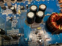
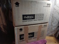
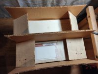
I have been working on a couple of tapped bass horn designs for many months now. This design is centered around a large 45x45x24" cabinet form and a single LMS Ultra 5400 driver. The weight with the 80lb driver loaded in is probably near 300lbs. The cabs are built from 18mm and 12mm BB and put together with PL premium construction adhesive and pocket screws. The drivers and access panel mount with 1/4x20 screws and threaded inserts. The finish is Duratex. A gallon and a half on each cab. The access panel is purposely large enough to allow for even 21" drivers. Other 18" or 21" drivers may be useable in this cab.

I did all of the simulating in HR but quickly jumped to Akabak after realizing that the process worked better designing the physical cabinet and horn fold first and then translating that into Akabak script instead of trying to optimize some simulation and then realizing that it would not fit into the cabinet, was too big, ended up with dead spaces in the cab, or otherwise had problems with real world buildability. This was a many month wash, rinse, repeat process of refinement. Once I got a fold layout that actually fit in the cab confines it was a manor of much tweaking to try and improve it with what was available. When I was happy with the compromises and that I would not get it any better I was lucky enough to have a friend offer to build the cabs at his cost at his professional cabinet shop. That took about 2 or 3 months. I had originally planned to build them myself but to be completely honest I am so glad that I didn't have to. I wouldn't have gotten them done near as quickly or with the same quality. Additionally these cabs were sort of a risk. There was no prototype and with something this large it would be easy to make mistakes and screw something up either in the build or while simulating. It wouldn't take much for it to be just and expensive and time consuming pile of scrap wood. There is also some concern over whether the driver will withstand the pressures in the horn, whether this driver is suited to a TH and about the effect that the folding will have on things. The fold of the horn is not elegant by any means. It has a number of 90 deg turns and many relatively short sections. I tried for weeks to come up with a fold to fit in this cabinet size with the right length and this is what I could get to work. It has compromises. We will see how bad they turn out to be. I tried to model the cabinet being built as accurately as possible but you can't get everything.

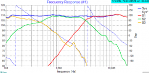
My inspiration for these was the Danley Th50 which I was quite impressed by when I heard it and the DTS-10 of which I own a pair of and happen to have been lucky enough to have had a very small hand in its development through correspondance with Tom. The goal is for something to use in LARGE open spaces and big rooms without a lot of gain and longer than normal listening distances. The goal was to cover 16-100hz well in a cab that wasn't too gigantic which is how I ended up at a size similar to a Labsub but slightly wider. That form fits almost perfectly into the space that I have available for the pair also. The effective lower limit on these according to the simulation should be just below 15hz at full power input. These should be safe from over excursion with 130v peaks anywhere above 14.5hz. I am going to use this pair as the anchor in my system at a warehouse space which is about 10,000cu ft and really lossy. There is not much room gain there to speak of until the really low freq's. I figure that 4 of these could rock a large commercial sized movie theater very well. That was really sort of the idea with this was, what would be suitable to cover 15-80hz for an Imax? So to answer the question it is something designed for my purposes and was never really meant to be a ht or music sub in someone's living room, being quite gigantic, heavy and rather overkill. A pair would be devastating in a typical domestic sized room or house. It is also not really suited to typical live sound or mobile SR as it has extension an octave lower than needed. Might be good for some high power dubstep or DnB though.


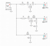
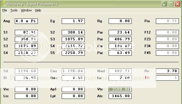
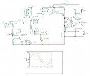
Anyway here is a rough HornResponse approximation of the Akabak script.

Gjallerhorninput.jpg


Here is the Akabak script. I ran out of sections. :dead:


|COMMENT:LMS5400 ULTRA 18hz 45x45x24 TH 020411 FINAL, no dead space, straight throat, with constriction, big mouth(LMS obstructs roughly 613cm2)

|=========================================================== =============================================

|REQUIRED AKABAK SETTINGS:

|File > Preferences > Physical system constants:

|Sound velocity c = 344m/s
|Medium density rho = 1.205kg/m3

|Sum > Acoustic power:

|Frequency range = 10Hz to 20kHz
|Points = 533
|Input voltage = 1.97V rms
|Integration = 2Pi-sr
|Integration steps = 1 degree ... 1 degree
|Integration method = Cross

|=========================================================== =============================================

Def_Const |Input Parameter Values
{
|Length, area and volume values converted to metres, square metres and cubic metres:

S1 = 82.90855e-4; |Horn segment 1 throat area (sq cm)
S2 = 308.14365e-4; |Horn segment 1 mouth area and horn segment 2 throat area (sq cm)
S3 = 453.98375e-4; |Horn segment 2 mouth area and horn segment 3 throat area (sq cm)
S4 = 226.85056e-4; |Horn segment 3 mouth area and horn segment 4 throat area (sq cm)/ brace area
S5 = 249.88796e-4; |Horn segment 4 mouth area and horn segment 5 throat area (sq cm)/ brace area
S6 = 513.6456e-4; |Horn segment 5 mouth area and horn segment 6 throat area (sq cm)
S7 = 729.21504e-4; |Horn segment 6 mouth area and horn segment 7 throat area (sq cm)
S8 = 517.6522e-4; |Horn segment 7 mouth area and horn segment 8 throat area (sq cm)
S9 = 254.60955e-4; |Horn segment 8 mouth area and horn segment 9 throat area (sq cm)/ brace area
S10 = 278.2318e-4; |Horn segment 9 mouth area and horn segment 10 throat area (sq cm)/ brace area
S11 = 570.7141e-4; |Horn segment 10 mouth area and horn segment 11 throat area (sq cm)
S12 = 846.68843e-4; |Horn segment 11 mouth area and horn segment 12 throat area (sq cm)
S13 = 579.57232e-4; |Horn segment 12 mouth area and horn segment 13 throat area (sq cm)
S14 = 795.34572e-4; |Horn segment 13 mouth area and horn segment 14 throat area (sq cm)
S15 = 587.76034e-4; |Horn segment 14 mouth area and horn segment 15 throat area (sq cm)
S16 = 628.4965e-4; |Horn segment 15 mouth area and horn segment 16 throat area (sq cm)
S17 = 894.92785e-4; |Horn segment 16 mouth area and horn segment 17 throat area (sq cm)
S18 = 637.70438e-4; |Horn segment 17 mouth area and horn segment 18 throat area (sq cm)
S19 = 908.89994e-4; |Horn segment 18 mouth area and horn segment 19 throat area (sq cm)
S20 = 647.05796e-4; |Horn segment 19 mouth area and horn segment 20 throat area (sq cm)
S21 = 684.16633e-4; |Horn segment 20 mouth area and horn segment 21 throat area (sq cm)
S22 = 1014.9946e-4; |Horn segment 21 mouth area and horn segment 22 throat area (sq cm)
S23 = 694.67089e-4; |Horn segment 22 mouth area and horn segment 23 throat area (sq cm)
S24 = 955.76983e-4; |Horn segment 23 mouth area and horn segment 24 throat area (sq cm)
S25 = 704.47613e-4; |Horn segment 24 mouth area and horn segment 25 throat area (sq cm)
S26 = 728.39915e-4; |Horn segment 25 mouth area and horn segment 26 throat area (sq cm)
S27 = 1037.1547e-4; |Horn segment 26 mouth area and horn segment 27 throat area (sq cm)
S28 = 739.10769e-4; |Horn segment 27 mouth area and horn segment 28 throat area (sq cm)
S29 = 1019.4091e-4; |Horn segment 28 mouth area and horn segment 29 throat area (sq cm)
S30 = 749.69967e-4; |Horn segment 29 mouth area and horn segment 30 throat area (sq cm)
S31 = 964.5552e-4; |Horn segment 30 mouth area and horn segment 31 throat area (sq cm)
S32 = 1367.7644e-4; |Horn segment 31 mouth area and horn segment 32 throat area (sq cm)
S33 = 989.80404e-4; |Horn segment 32 mouth area and horn segment 33 throat area (sq cm)
S34 = 1038.2765e-4; |Horn segment 33 mouth area and horn segment 34 throat area (sq cm)
S35 = 1428.0236e-4; |Horn segment 34 mouth area and horn segment 35 throat area (sq cm)
S36 = 1058.7029e-4; |Horn segment 35 mouth area and horn segment 36 throat area (sq cm)
S37 = 1060.4949e-4; |Horn segment 36 mouth area and horn segment 37 throat area (sq cm)
S38 = 1509.5979e-4; |Horn segment 37 mouth area and horn segment 38 throat area (sq cm)
S39 = 1075.8948e-4; |Horn segment 38 mouth area and horn segment 39 throat area (sq cm)
S40 = 532.2565e-4; |Horn segment 39 mouth area and horn segment 40 throat area (sq cm)/ brace area
S41 = 682.62005e-4; |Horn segment 40 mouth area and horn segment 41 throat area (sq cm)/ brace area
S42 = 1413.3813e-4; |Horn segment 41 mouth area and horn segment 42 throat area (sq cm)
S43 = 2501.1503e-4; |Horn segment 42 mouth area and horn segment 43 throat area (sq cm)
S44 = 2065.1744e-4; |Horn segment 43 mouth area and horn segment 44 throat area (sq cm)
S45 = 2067.7094e-4; |Horn segment 44 mouth area and horn segment 45 throat area (sq cm)
S46 = 1505.2217e-4; |Horn segment 45 mouth area and horn segment 46 throat area (sq cm)/ (1505.2217 with driver restriction, 2118.2217 without)
S47 = 2167.5538e-4; |Horn segment 46 mouth area and horn segment 47 throat area (sq cm)
S48 = 2237.6765e-4; |Horn segment 47 mouth area and horn segment 48 throat area (sq cm)
S49 = 2611.6741e-4; |Horn segment 48 mouth area (sq cm)


L12 = 23.64486e-2; |Horn segment 1 axial length (cm)
L23 = 54.00802e-2; |Horn segment 2 axial length (cm)
L34 = 8.93572e-2; |Horn segment 3 axial length (cm)brace area
L45 = 47.001684e-2; |Horn segment 4 axial length (cm)
L56 = 3.214878e-2; |Horn segment 5 axial length (cm)
L67 = 3.504946e-2; |Horn segment 6 axial length (cm)
L78 = 3.563112e-2; |Horn segment 7 axial length (cm)
L89 = 2.418334e-2; |Horn segment 8 axial length (cm)brace area
L910 = 48.208438e-2; |Horn segment 9 axial length (cm)
L1011 = 2.373376e-2; |Horn segment 10 axial length (cm)
L1112 = 4.11353e-2; |Horn segment 11 axial length (cm)
L1213 = 4.7655988e-2; |Horn segment 12 axial length (cm)
L1314 = 4.3843448e-2; |Horn segment 13 axial length (cm)
L1415 = 3.827526e-2; |Horn segment 14 axial length (cm)
L1516 = 40.694864e-2; |Horn segment 15 axial length (cm)
L1617 = 4.298442e-2; |Horn segment 16 axial length (cm)
L1718 = 4.9505108e-2; |Horn segment 17 axial length (cm)
L1819 = 4.9652428e-2; |Horn segment 18 axial length (cm)
L1920 = 4.418838e-2; |Horn segment 19 axial length (cm)
L2021 = 37.065458e-2; |Horn segment 20 axial length (cm)
L2122 = 4.912106e-2; |Horn segment 21 axial length (cm)
L2223 = 5.5748428e-2; |Horn segment 22 axial length (cm)
L2324 = 5.1532028e-2; |Horn segment 23 axial length (cm)
L2425 = 4.58724e-2; |Horn segment 24 axial length (cm)
L2526 = 35.401758e-2; |Horn segment 25 axial length (cm)
L2627 = 4.999228e-2; |Horn segment 26 axial length (cm)
L2728 = 5.6479948e-2; |Horn segment 27 axial length (cm)
L2829 = 5.4557168e-2; |Horn segment 28 axial length (cm)
L2930 = 5.119624e-2; |Horn segment 29 axial length (cm)
L3031 = 47.806102e-2; |Horn segment 30 axial length (cm)
L3132 = 6.366002e-2; |Horn segment 31 axial length (cm)
L3233 = 6.6675e-2; |Horn segment 32 axial length (cm)
L3334 = 32.559498e-2; |Horn segment 33 axial length (cm)
L3435 = 6.745478e-2; |Horn segment 34 axial length (cm)
L3536 = 6.860286e-2; |Horn segment 35 axial length (cm)
L3637 = 1.203452e-2; |Horn segment 36 axial length (cm)
L3738 = 7.239254e-2; |Horn segment 37 axial length (cm)
L3839 = 7.780782e-2; |Horn segment 38 axial length (cm)
L3940 = 1.651254e-2; |Horn segment 39 axial length (cm)brace area
L4041 = 51.303936e-2; |Horn segment 40 axial length (cm)
L4142 = 3.48996e-2; |Horn segment 41 axial length (cm)
L4243 = 12.146026e-2; |Horn segment 42 axial length (cm)
L4344 = 10.563352e-2; |Horn segment 43 axial length (cm)
L4445 = 1.200658e-2; |Horn segment 44 axial length (cm)
L4546 = 23.711916e-2; |Horn segment 45 axial length (cm)
L4647 = 23.490936e-2; |Horn segment 46 axial length (cm)
L4748 = 33.151826e-2; |Horn segment 47 axial length (cm)
L4849 = 6.847332e-2; |Horn segment 47 axial length (cm)

Vtc = 3500.00e-6; |Throat chamber volume (cc)
Atc = 1465.00e-4; |Throat chamber cross-sectional area (sq cm)

|Parameter Conversions:

Sd = 1194.60e-4; |Diaphragm area (sq cm)

Ltc = Vtc / Atc;
}
|=========================================================== =============================================

|Network node numbers for this tapped horn system:

| 0-Voltage-1
| |
| -Chamber-5-Driver---
| | |
|8-Segment-9-Segment-10-Segment-11-Segment-12-Segment-13-Segment-14-Segment-15-Segment-16-Segment-17-Segment-18-Segment-19-Segment-20-Segment-21-Segment-22-Segment-23-Segment-24-Segment-25-Segment-26-Segment-27-Segment-28-Segment-29-Segment-30-Segment-31-Segment-32-Segment-33-Segment-34-Segment-35-Segment-36-Segment-37-Segment-38-Segment-39-Segment-40-Segment-41-Segment-42-Segment-43-Segment-44-Segment-45-Segment-46-Segment-47-Segment-48-Segment-49-Segment-50-Segment-51-Segment-52-Segment-53-Segment-54-Segment-55-Segment-56-Radiator

|=========================================================== =============================================

Def_Driver 'Driver'

Sd=1194.60cm2
Bl=26.93Tm
Cms=1.19E-04m/N
Rms=8.58Ns/m
fs=20.5001Hz |Mmd = 482.71g not recognised by AkAbak, fs calculated and used instead
Le=2.80mH
Re=3.78ohm
ExpoLe=1

System 'System'

Driver Def='Driver''Driver'
Node=1=0=5=53

Duct 'Throat chamber'
Node=5=9
SD={Atc}
Len={Ltc}
Visc=0


Waveguide 'Horn segment 1'
Node=8=9
STh={S1}
SMo={S2}
Len={L12}


Waveguide 'Horn segment 2'
Node=9=10
STh={S2}
SMo={S3}
Len={L23}


Waveguide 'Horn segment 3'
Node=11=10
STh={S4}
SMo={S3}
Len={L34}

Waveguide 'Horn segment 4'
Node=11=12
STh={S4}
SMo={S5}
Len={L45}

Waveguide 'Horn segment 4B'
Node=11=12
STh={S4}
SMo={S5}
Len={L45}

Waveguide 'Horn segment 5'
Node=12=13
STh={S5}
SMo={S6}
Len={L56}

Waveguide 'Horn segment 6'
Node=13=14
STh={S6}
SMo={S7}
Len={L67}

Waveguide 'Horn segment 7'
Node=15=14
STh={S8}
SMo={S7}
Len={L78}

Waveguide 'Horn segment 8'
Node=16=15
STh={S9}
SMo={S8}
Len={L89}

Waveguide 'Horn segment 9'
Node=16=17
STh={S9}
SMo={S10}
Len={L910}

Waveguide 'Horn segment 9B'
Node=16=17
STh={S9}
SMo={S10}
Len={L910}

Waveguide 'Horn segment 10'
Node=17=18
STh={S10}
SMo={S11}
Len={L1011}

Waveguide 'Horn segment 11'
Node=18=19
STh={S11}
SMo={S12}
Len={L1112}

Waveguide 'Horn segment 12'
Node=20=19
STh={S13}
SMo={S12}
Len={L1213}


Waveguide 'Horn segment 13'
Node=20=21
STh={S13}
SMo={S14}
Len={L1314}


Waveguide 'Horn segment 14'
Node=22=21
STh={S15}
SMo={S14}
Len={L1415}


Waveguide 'Horn segment 15'
Node=22=23
STh={S15}
SMo={S16}
Len={L1516}

Waveguide 'Horn segment 16'
Node=23=24
STh={S16}
SMo={S17}
Len={L1617}

Waveguide 'Horn segment 17'
Node=25=24
STh={S18}
SMo={S17}
Len={L1718}

Waveguide 'Horn segment 18'
Node=25=26
STh={S18}
SMo={S19}
Len={L1819}

Waveguide 'Horn segment 19'
Node=27=26
STh={S20}
SMo={S19}
Len={L1920}

Waveguide 'Horn segment 20'
Node=27=28
STh={S20}
SMo={S21}
Len={L2021}

Waveguide 'Horn segment 21'
Node=28=29
STh={S21}
SMo={S22}
Len={L2122}

Waveguide 'Horn segment 22'
Node=30=29
STh={S23}
SMo={S22}
Len={L2223}

Waveguide 'Horn segment 23'
Node=30=31
STh={S23}
SMo={S24}
Len={L2324}


Waveguide 'Horn segment 24'
Node=32=31
STh={S25}
SMo={S24}
Len={L2425}


Waveguide 'Horn segment 25'
Node=32=33
STh={S25}
SMo={S26}
Len={L2526}


Waveguide 'Horn segment 26'
Node=33=34
STh={S26}
SMo={S27}
Len={L2627}

Waveguide 'Horn segment 27'
Node=35=34
STh={S28}
SMo={S27}
Len={L2728}

Waveguide 'Horn segment 28'
Node=35=36
STh={S28}
SMo={S29}
Len={L2829}

Waveguide 'Horn segment 29'
Node=37=36
STh={S30}
SMo={S29}
Len={L2930}

Waveguide 'Horn segment 30'
Node=37=38
STh={S30}
SMo={S31}
Len={L3031}

Waveguide 'Horn segment 31'
Node=38=39
STh={S31}
SMo={S32}
Len={L3132}

Waveguide 'Horn segment 32'
Node=40=39
STh={S33}
SMo={S32}
Len={L3233}

Waveguide 'Horn segment 33'
Node=40=41
STh={S33}
SMo={S34}
Len={L3334}

Waveguide 'Horn segment 34'
Node=41=42
STh={S34}
SMo={S35}
Len={L3435}

Waveguide 'Horn segment 35'
Node=43=42
STh={S36}
SMo={S35}
Len={L3536}

Waveguide 'Horn segment 36'
Node=43=44
STh={S36}
SMo={S37}
Len={L3637}

Waveguide 'Horn segment 37'
Node=44=45
STh={S37}
SMo={S38}
Len={L3738}

Waveguide 'Horn segment 38'
Node=46=45
STh={S39}
SMo={S38}
Len={L3839}

Waveguide 'Horn segment 39'
Node=47=46
STh={S40}
SMo={S39}
Len={L3940}

Waveguide 'Horn segment 40'
Node=47=48
STh={S40}
SMo={S41}
Len={L4041}

Waveguide 'Horn segment 40B'
Node=47=48
STh={S40}
SMo={S41}
Len={L4041}

Waveguide 'Horn segment 41'
Node=48=49
STh={S41}
SMo={S42}
Len={L4142}

Waveguide 'Horn segment 42'
Node=49=50
STh={S42}
SMo={S43}
Len={L4243}

Waveguide 'Horn segment 43'
Node=51=50
STh={S44}
SMo={S43}
Len={L4344}

Waveguide 'Horn segment 44'
Node=51=52
STh={S44}
SMo={S45}
Len={L4445}

Waveguide 'Horn segment 45'
Node=53=52
STh={S46}
SMo={S45}
Len={L4546}

Waveguide 'Horn segment 46'
Node=53=54
STh={S46}
SMo={S47}
Len={L4647}

Waveguide 'Horn segment 47'
Node=54=55
STh={S47}
SMo={S48}
Len={L4748}

Waveguide 'Horn segment 48'
Node=55=56
STh={S48}
SMo={S49}
Len={L4849}

Radiator 'Horn mouth'
Node=56
SD={S49}
__________________

Unphased by EQ

Hi all, some may have seen in other threads that i often talk about having a separate volume control on each driver section, that can be adjusted underneath an overall volume control.

I do this for both loudness compensation, and for adjusting tonal balance of individual tracks which i find can vary like a politician, haha

Anyway, i believe the key to the happy results i've been getting with this technique, is how that changing relative SPL levels between driver sections doesn't effect phase.

Reason being, the xovers used are linear phase, and steep, which leaves little room for summation problems away from the xover freq.

Below is a quick set of measurements just taken from a 3-way, to show what I'm trying to explain.
Mid is 12" cone 120-650Hz. HF is coax CD 650-3.2kHz. VHF is coax CD 3.2kHz up.
All were 1/6th smoothing magnitude, 1/12th phase. Indoors in really noisy conditions, everybody home both🙂 + 🙁 lol,... and is why a sub wasn't brought into the test as well.

Here's the 3-way with all sections running at equal level.
Please note the level phase trace.
3-way all flat L.JPG

Here's with each of the 3 sections individually raised +10dB.
Please note the level phase traces !
3-way Mid 120-650Hz  +10dB L.JPG
3-way HF 650-3200Hz  +10dB L.JPG
3-way VHF 3200Hz up +10dB L.JPG

+10dB is obviously a hell of a lot of boost, likely to never be used.
But I've found many songs that can use +5dB on the sub, and -5dB on HF/ VHF. And that's on top of a medium downslope house curve.

The neat thing though, is it doesn't matter whether boosts or cuts are used, smiley face, frowny face, whatever,...it never sounds whacky like it can when trying to adjust tonal balance with normal EQs.
And it works so easily for almost every track encountered, at whatever volume.

fwiw...Just though some folks might be interested...
  • Like
Reactions: Oabeieo

NEW (2) Electro Voice EV 8HD Diffraction Horns Metal PAIR brackets screws

$99 or best offer plus shipping
If you can email me a label that would be best, if you're outside New England.

Attachments

  • IMG_20201209_140511.jpg
    IMG_20201209_140511.jpg
    964.1 KB · Views: 103
  • IMG_20201209_140535.jpg
    IMG_20201209_140535.jpg
    829.7 KB · Views: 97
  • IMG_20201209_140611.jpg
    IMG_20201209_140611.jpg
    825 KB · Views: 104
  • IMG_20201209_140618.jpg
    IMG_20201209_140618.jpg
    847 KB · Views: 97
  • IMG_20201209_140620.jpg
    IMG_20201209_140620.jpg
    645.1 KB · Views: 91
  • IMG_20201209_140650.jpg
    IMG_20201209_140650.jpg
    888.6 KB · Views: 75

Trying to test power supply

I've been trying to test a few mini itx power supply units (PW-200M) which I've accumulated and which have 20 pin ATX connectors.

More info here.

200 Watt DC-DC ATX

and photo below

https://www.diyaudio.com/forums/attachment.php?attachmentid=905865&stc=1&d=1609255652

Originally I tried the "paper clip" test shorting out the "power on" pin 14 to ground - I used the adjacent pin 15 - with a paper clip. Then I connected up a 12 volt power supply to the feed in, and then checked for voltages at the 12 and 5 volt pins - nothing!

Next stage, after further Googling, I found an article suggesting that as well as shorting out pin 14 and 15, I needed to add load, the suggestion was to use a 5W 10 ohm resistor to add load. I bought a resistor and connected it across pins 3 and 4 and again connected up to my 12volt bench supply . Again nothing!

This was the same with all 3 PW-200M's I tried. Thinking it odd that all 3 could be faulty, I connected one of the power supplies to a mini ITX motherboard, applied 12 volts to it and the motherboard fan spun into action and I could detect voltages from the various power supply leads. This was the same with both the other 2 power supply units.

Now I know I could have saved myself all the hassle by just using the motherboard test in the first place, but initially the paper clip test seemed so simple.

Just curious as to why the paper clip test doesn't work. Anyone any ideas?

PS I've checked the voltages across the various pins of the ATX connector when it's powered up to the motherboard and the output voltages all correspond to ones expected from a 20 pin ATX connector ,so I don't think it's a non standard design.

Thanks

Alchad

Attachments

  • psu5.jpg
    psu5.jpg
    197.5 KB · Views: 178

Audiophile JLH ab

905116d1609052952-audiophile-jlh-ab-audiophile-jlh-jpg


This topology is described here http://www.keith-snook.info/wireles...orld-1970/15-20W Class AB Audio Amplifier.pdf
I will try to design to its best keeping it simplest possible.
This is first attempt which gave +/- 40v excursion with non sticky saturation. The distortion is 0.0008% at 50W 1khz for now. The IRF540 is assigned arbitrary to be selected for best.
T14/15 do not make part of the circuit, they simulate the function of LM334 1ma.

Attachments

  • AUDIOPHILE JLH.JPG
    AUDIOPHILE JLH.JPG
    90.2 KB · Views: 1,549

Ir2153 amplifier modified for higher drive current

This amp I make , sound like a scooter when I power it on . Then when I plug it off the noise decay with increasing frequency and then the sound vanish.
I have a gate resistor of 10 ohms . With irfp150 i.
I use 50.0.50 supply with 12v external power supply .
A totenpole arrangement of bd139 and 140 is present inbetween the ir2153 and irfp150

Diy amplifier hum

Hello,
I made an amplifier using Hitachi HA13158a IC. Using this schematic:
HA13158A.jpg

For power supply I used SMPS from Logitech z533 2.1 pc speakers.
I cant tell much about it, but I know it was working normaly with the logitech amplifier. It outputs 17,7v.

Logitech_Z333_PSU_board_above_full_tehnotone.com_.jpg

I live in Europe and both the SMPS from amplifier and my TV don`t have earth connections.

Now I have problem with buzz.
If I turn on the amplifier without rca cables connected to it the buzz is really silent.
If I connect RCA cables to it (with nothing connected on the other side) buzz becomes loud, cables act like an antenna.
If I connect mobile phone to it buzz is almost gone. Really silent buzz remains.
But if I connect amplifier to the tv the buzz is much lounder than with the mobile phone.
If I turn off the tv the buzz becomest even louder.

I ordered TOSLINK to analog adapter mainly because I can`t control volume level of headphones jack without going into settings on tv, but it will also break possible ground loop to the tv.
But I have a feeling that the buzz will remain (because there is a slight buzz with the phone connected).

What can I do to solve the problem?

Thank you.

Rod Elliot's Amplifier Powered Speaker Protection

Hi, Found this interesting article on Amplifier Powered Speaker DC Protection by Rod Elliot at Speaker Protection.

I find the idea slightly dubious. But, what would I know compared to Rod? If it worked it would be a really neat and useful idea. What do you think? Any ideas?

Perhaps it could be modified to protect the speaker agains excessive signal output as well (caused by idiots turing up the volume too far or amp oscillation).

Regards
Mr Tibouchina

Does a Variable power supply improve on sound quality

Hi,

I have always wondered, does the supply voltage affect sound quality.

Let's see how this comes about. At lower at mid volumes, does it make sense to lower the supply voltage to increase the PWM %.

Example does at lower volume a original signal required a duty cycle of 1%. If the voltage is reduced 4×. The Duty cycle would increase to 4%.Amplitude reduces by 75%

So in theory, it should be better. But can you hear it?

Oon

HCA-3500 questions

When comparing HCA-3500 to JC-1, I noticed that the Zener diodes for the MOSFET driving transistors are different. In HCA-3500, 30V zener is used, while in JC-1 18V is used. Both are noted as D35/D36 in the schematics.

Any one know the reason ? and how this affects the sound ?

It would be great if John Curl could help understand this.

Thanks,
Ray

What's in the box?

Out of contention came a suggestion. An argument in another one of my threads here brought the Schitt Magni 3 headphone amp to my attention. The thing is only $99 at Schitt's web site, and it boasts some decent specs.

I intend to get one as a data point for a low cost headphone amp, also to see if I like the way it sounds. I plan to pop the hood when I get the amp, but in the meantime, I can speculate on what's inside based on their posted description and specs, realizing also that there can't be all that much in the box for just 99 bucks. That line of thought has led me to several simulated designs that I'll present in this thread, some better than others.

First off, the amp is described as all discrete bipolar, current feedback, with total DC path from input to output, and a servo to correct offset.

As time permits, I'll post several design simulations with distortion that I have arrived at over the past couple of days. Some fit all the criteria in the product description, some do not. Some designs (esp a couple of early attempts) have flaws that may make them not worth building, but will be presented anyway as part of the learning experience. One of these designs may duplicate what's in the box - then again, maybe not. More later.

Got a buzz

One of those two 6x6550 amps I’ve been building had a weird buzz that took me the better part of a week to track down. One was dead silent, the other sounded like filter cap charging currents were being injected into the signal. Because of that characteristic “sound” it had me off chasing my tail looking in the wrong paces. Isolated to the front end - then finally the input tube itself. Swapping to another 5751 cured it. What I can’t figure out is why - I have no idea what mechanism could be in play. It wasn’t hum being induced, that would be mostly 60 Hz not 120 with a strong 3rd harmonic. Megohm measurements don’t show any h-k leakage, which would be 60 Hz anyway. It’s not a hum/ripple balance issue, or even just excessive ripple - that would have shown up with the input tube pulled. Not likely with a heavily filtered (cap multiplier) mosfet regulator for the front end. That was needed just to get the *hiss noise* down to an acceptable level. That input stage is set up as a gain stage/concertina with only 75 volts on the 2nd cathode followed by a short-tailed SN7 pair which by itself is well enough balanced to be hum free. Nothing exotic going on, so where would be wrong with that tube to cause the buzz? Would it be ok for me to use in something else, perhaps with a DC heater, or should it be considered potentially hazardous? What about the odds of this happening, on any given Sunday?

differential amp issues

Small 2 channel class B assian amp.
Does not have any output but powers up fine and draws 0.3A at idle. I do not have any schematic on this one.

Rail voltages are fine, +-15v are dead stable.

No shorted diodes or transistors. Both channels are acting identical, so this should be a general issue, not channel related. I will be referring to only one of the channels for simplicity.

I've read everything in Perry's guide about amplifier stages.
I've narrowed down the issue somewhere in differential amp or/and voltage amplifier.

The voltage amplifier does not have any output - ( uses A1268 + C3200). There is +-22v at both emitter and base, and 0v the collector so it's not driving the output stage.

Base of the VAS transistors are directly connected to the collector of the differential amps - (uses A1015 + C1815). This amp uses constant current source for the differential amp stage.

On the bases of the differential amp transistors I have a nice clean sinewave of 40hz - this is the input.
Collectors are purely DC - +-22v (from the guide i know i can't see here any sinewave but this should be driving the VAS).
Emitters have half sinewave sitting at them - one differential amp is having only top, the other one only the bottom part of the sinewave ground referenced.

I can't wrap my head around this. There are no shorted transistor or diodes, traces are fine, didn't find any bad resistor and both channels are acting identically...so what is affecting both channels and can cause this ?

There is an optocoupler 817c, but I've already changed it and no difference.

Any ideas ?

Attachments

  • 0.jpg
    0.jpg
    793.4 KB · Views: 138
  • 1.jpg
    1.jpg
    346.5 KB · Views: 131
  • 2.jpg
    2.jpg
    626.2 KB · Views: 126
  • 3.jpg
    3.jpg
    449.4 KB · Views: 127

my NHB-108 clone (pics)

recently bought this one on an impulse buy from that auction site. a seller on the west coast who mentioned the following additional work on it:

“a complete DIY audio Dartzeel Assembled Power Amplifier NHB108 with aluminum chassis, upgraded capacitors, 4 pieces of SPRAGUE or BC 75V 39000UF capacitor, and Japan OMRON horn protection circuit and high power soft start.

It's one of my personal audio collection made by a professional audio recording engineer, all parts have been carefully selected, matched and test before assembled. all welding/soldering inside using silver tin wire.


Input Impedance: 100KΩ
Line Gain: +26dB
THD+N: -100dB(no load) -60dB (8Ω)
CrossTalk: - 125 dB
SNR: 115dB
Freq. Response: 10Hz ~ 20KHz
Max. RMS Power: 140W (8Ω) 200W (4Ω)
Volue: 440x330x160 (W*D*H)
G.W. 24kg. “

Bybee Slipstream purifiers FS

I have eight quantum purifiers for sale 4 small and four large. These have been sitting in my parts box for about 8 years so they are the original small and large versions not the newer “copper” or “gold” ones. Never soldered and look like new.
Large are about 2” long body and small are about 1/2” body.

I think they originally sold for around $100 apiece, but if you take all 8 I’ll sell for $250 shipped to the lower 48, have some new winter projects cooking and need funds. eBay feedback under same username.

No such thing as a 32-bit DAC!

I just need to rant about this, 'cause nobody else seems to be doing it, and will understand if this gets deleted.

But, here goes:

WHY do government regulators continue to allow ESS, Burr-Brown, Asahi & etc. to sell "32-bit dac" chips, when this is PLAINLY OUTRIGHT FRAUD?

Just 'cause you cram a 32bit(allegedly) digital filter into the same chip package as an optimistically 24bit dac, HOW does that give anyone the proper right to call it a "32-bit DAC" chip?

How is that not fraud?

The deceiptful chip makers call them 32bit dacs, then the dac/player makers rely on that fraud to call their units 32bit, and the public buys them thinking they're getting 32bit performance, when they are damn lucky if they're getting even 22bit of dynamic range & snr.

How is that not fraud?

Why is there nobody holding the chip & gear makers accountable?

Slot port frustration

Howdy,
I'm pretty deep in the rabbit hole trying to figure out a slot port design for a vented car audio sub (JL12W7AE3). I've got a few questions and will take any single answer to any of them as a blessing.

So JL recommends slotted ports over round for whatever reason and I'm in the ballpark of a 2.25"x11.5" port area. It's a fairly typical box design with one wall of the box serving as one wall of the port and an extra wall inside the enclosure to box in the vent. The port length based on some calculators is in the range of 30" for fb=32Hz which means the port has to make one turn around a corner of the enclosure to get the Lv I need given the overall dimensions of the box (box is ~26"x13"x16" but the 26" is what I can adjust most easily). But then there's a ton of uncertainty in the Lv. So, questions:

1) I can't find a port length formula without baked-in units. One post on this forum actually uses c^2/(16pi) but has a factor of 10 in it that I suspect is a conversion factor (when I use it with units of inches, my port length comes out ~10x too long). Others assume SI units (2.35625e4 is 10c^2/(16pi) in m/s). I stared at my math a million times (more or less) and can't find an error, so I suspect that factor of 10, but you tell me. For now, I'll use the 2.35625e4 and convert the Lv result from m to in.

2) At least one online vent calculator distinguishes between slot, square and round vent shapes. It also gives different solutions with the same effective D, so the underlying equations are different. Of course, the equations aren't given. For square or slot, I have to put in the port area's width and length, so maybe aspect ratio is involved. Dunno. Any intuition on that? I'm only 5:1 with my port area dimensions and these are the same as the "recommended ported enclosure" port specs from JL (just being safe), though their box is too cubic for what I want. Many say just compute effective diameter from slot area and pretend it's round, but I'm not convinced. Assuming it's round gets less obvious when I consider k.

3) k=?. Since vents have two ends, I have to figure out my effective k by summing the k for both ends, and I have different questions about each end, so...

3a) k at the vent mouth: I see plenty of stuff about k for tube ports, great stuff all over. I'm going to add a 3/4" radius bezel/flare around the port mouth, so I'm guessing maybe I just add 3/8" to Lv if I even bother (aside from the k correction). The slot mouth is on the same box face as the sub baffle and the slot is vertical relative to the floor of the vehicle - on purpose; if I put the slot under the sub, it makes the box taller and then the floor affects the effective port length. So the vent opens and next to one long edge of the mouth is the speaker. There's "nothing" next to the other long edge of the mouth (no baffle, just the 3/4" radius flare on the outside wall of the box). If I had a baffle all the way around the mouth, I'd have one value for k. If I don't, I have another k. With the speaker on one side and no baffle on the other, I'm not sure. Does the speaker side count as a baffle? If it's playing and resonating near fb, I'd think the in-phase pressure from the sub would act as an extension of the inner vent wall to some extent. What do you do with a slot that has two different conditions on each of its long edges?

3b) Inside the box, on the other end of the port, the port makes a turn and then ends part-way along the other enclosure wall, the one opposite the sub baffle. On the inner side, I'll again have a 3/4" radius flare that wraps 270 degrees around the end of the interior wall, but the other wall extends many more inches. Again, I can add 3/8" to Lv for the flare (independent of k), but what k do I use? JL says add W/2 where W is 2.25" in my case. Obviously, this doesn't play nice with the k*D term in the Lv equation because it doesn't account for a rectangular port. The W/2 stuff makes some intuitive sense. I could pick any W I want, in theory, and get the same effective D, so there can't be one k value to rule them all. Aside from having one side with a wall and the other without, the interior wall also lacks a baffle; it just wraps around the 3/4" radius flare. So k is particularly a mystery here.

So I've got myself wrapped around the axle. I think slot ported requires some special treatment because it's so far from having a circular cross section and a single k*D doesn't make intuitive sense, particular with these end conditions. I can cop out and use the JL vented enclosure port length and W/2 guidance, maybe compensating a tad bit for the radiused flares, but I'm a scientist and I really want to understand this a lot better.

Thanks in advance!
-Mack

Help with PS for 300B amplifier please!

I know there are a million 300B amp schematics and power supplies. Most are for 350v across the 300B. My design calls for about 400v across the 300B plus a 80v cathode and about 7v drop across the output transformer. This is at 90mA. My driver will be an EL84 pentode running at about 20mA or so. So a total of 220mA.

Should i split this up into 2? and design a power supply for 110mA? I have tried PSUDII and at 220mA its hard NOT to go over the max current of any tube rectifier i pick.

The 300B heaters will be powered by DC and common mode chokes.

Maybe a hybrid power supply?

The OPT will be the Edcor 3K CXSE25-3K.

Edcor does offer some 350-0-350 and 400-0-400 power transformers.

Any help would be greatly appreciated. Or just a point into the right direction. I will post my power supply design here.

Thank you in advance.

Mini Crescendo worth reviving?

I am finally getting back into audio gear. Raising kids has life go off in different directions? Back in 1984 I built the Mini Crescendo from Elektor plans but my own board layout. I built it in Germany before my move to Canada. It was last powered on around 1998. The toroid on the build is a 220V type which won’t work too well on our 110V here.

Question, if I picked up a new Hammond Mfg transformer I am stuck choosing the 60V or 80V Center Tapped. I am leaning towards 2x30V. Considering it’ll be over $100 and the filter caps also need replacing I am wondering if this venture is even worth it?

Adi

Simple crossover for woofer

Hi, i have a problem. So at the moment my speakers are playing without crossover expect the tweeter which has a capacitor .
The woofers i took out of old sony speakers 3way. In one boxe i have 2 woofers. But i noticed that one woofer plays more fullrange than the other one, and also the other one has a bigger magnet . One is more like a midbass and the other one is a woofer. This has made a problem because now the speakers together has too much midbass/midrange and cant hear the tweeter unless i turn it up more . i tried to take out the woofer not the midbass woofer and everything sounded better but i still want to use the other woofers.
So is there a way to use simple Low Pass crossover for the woofers ?
Its weird that they have done it this way , why not just use a crossover ?

Do I need to reform brand new PSU caps for a tube amp?

Caps are new CDE Illinois 47uF/500V
Amp is original Peavey Classic 30
Supplier is Mouser


Can I assume that these are new enough that they don't need reforming before I install them?


If I DO need to reform them, the best I can do for now is 50VDC and then 100VDC with the equipment I have on hand...


If I install them as is and let the amp idle for a few minutes or hours will they reform (at lease somewhat) while the amp is idling?


I want this amp to be as hum free as possible.

Regulating high voltage (up to 450V) has become as easy as a LM317!

I dont know why but there is almost no info about the LR8 regulator...

Its essentially a LM317 but works up to 450V and does up to 10mA.

Pretty much enough for any 12AX7 contraption even a phase inverter.

There are three versions: TO92,TO252(DPAK),TO243AA(SOT89)

The TO92 can do the least power dissapation at only 0,74W
TO243(SOT89) does 1,6W
TO252 does up to 2,5W

I intend to add a pass transistor at the output really extending the current and dissapation capabillity of the contraption and also taking the feedback from the emitter so that the voltage is absolutely stable. I intend to replace every RC filter in every one of my old radios by this since the radios I own have quite the severe humm problem at high gains.

My other usecase will be to regulate voltages within a tube ampliffier. I have a upcoming 100W KT88 amp project in which I will be using this regulator to regulate the HV for the phase inverter and the preamp tube and also the negative bias voltage for the KT88's. Good stuff.

Try it out I sure will in two days in my radios.

And its pretty cheap aswell.

Datasheet https://www.tme.eu/Document/49ed538122efa3e11e59182b05d3cd61/lr8.pdf

Bose Amplifier Basic Audi AS4 - A6 - S6 - 4F- 4F0035223 wiring diagram

I have a Sound Amplifier Basic Audi AS4 - A6 - S6 - 4F- 4F0035223 connected to MMI MUTE INTERFACE MODULE SCORPION AUDI A6 C6 Q7 VA6600ECU. 04-11 . MODEL A6 C6 S LINE. Anybody who has a wiring diagram for amplifier ? I suppose MMI it's not important on audio terms.

Attachments

  • Bose-02-poze noi-04.jpeg
    Bose-02-poze noi-04.jpeg
    140 KB · Views: 249
  • Bose-02-poze noi-02.jpeg
    Bose-02-poze noi-02.jpeg
    252.5 KB · Views: 251

TPA1620 pop/click problem

Hello,
I'm working on the HP amplifier which has a TPA1620 on the output as a buffer. It has 1k ohm on the inverted feedback. I use it as a non-inverting amp.
There is also switching psu for +-15V, after that have a positive and negative LDO with 47u tantal.
Pos and Neg voltage increases simultaneously 30ms, 0 to 15V. On the 32ohm output I have measured two picks that made a click, one is positive 3.4V that last 3ms and 2nd is negative after that pos -4.4V and decreases much longer.
I found from some articles that it is expected, isnt it? If so, I want to decrease it. On the HP I hear it but not too much (not high-end result) but on the iEM it is very unpleasant.
I don't have any DC offset on the input/output of the amp, and don't use capacitor at the output.
That pop is heard just when PSU is enabled, after that it works good.
Does anyone has similar experience and what could be the solution?

Power supply for small DAC and NE5532 preamp

Hello,
I bought cheap DAC to convert toslink coming from my TV to analog.
Because output of this DAC was way to low I added single stage preamplifier based on NE5532.
Now my question is, what would be better, I`m worried about ground loop noise problems.
1.) DAC on it`s cheap smps 5v 1500mA and amplifier on seperate linear regulated power supply.

2.)DAC and preamp on same transformer diode bridge, smoothing caps, then 5v linear regulator for dac and 12v linear for preamp? -This one sims like a good option to me, but I am affraid that I will get digital noise on preamp.

3.) DAC and preamp on different linear regulated power supplies?

On both devices audio gnd is gnd (not shifted) if this plays any rolle.

Crossover question

Nelson posted this simple crossover for use with the SAL 08c08 with a 15" Eminence woofer on an open baffle. Any idea what the crossover point is for the woofer using this crossover ? I have a feeling the impedance rise at resonance will make calculations rather complicated .

Attachments

  • SAL8 OB PASSIVE W FILTER (1).gif
    SAL8 OB PASSIVE W FILTER (1).gif
    16.2 KB · Views: 95

Looking for a guide to using LTSpice for amplifier design

I am relatively new to LTSpice and wanted to find a guide to amplifier design using LTSpice or any circuit sim for that matter. Something that lines out what parameters you are looking for. How to measure them and make adjustments etc.. There must be something out there that walks you thru this process with some education along the way?
Doesn't have to be free either. I would gladly pay for it if its a worthwhile reference.

Jeff

Smoke came from TPA3116

Hi everyone

Please help me in ways to fix this problem with the tpa3116

I connected wrong terminals and saw some smoke coming out of the tpa3116 amp then i immediately pulled the wire out of the amp.

After connecting the correct wires it's now turning on but with these problems.

The subwoofer is giving very low sound.
When i connect more than 12v to the amp it disconnects the Bluetooth connection and sound start to break

Otherwise with 12v the two channels left and right are giving clear sound but very less sound to subwoofer channel.

Is there a way to fix this now.
Please check the attached pics aswell..

TIA🙏🙏

Attachments

  • 20201221_181525.jpg
    20201221_181525.jpg
    1 MB · Views: 159
  • 20201221_181512.jpg
    20201221_181512.jpg
    1,019 KB · Views: 162
Projects by fanatics, for fanatics
Get answers and advice for everyone wanting to learn the art of audio.
Join the Community
507,760
Members
7,887,257
Messages

Filter

Forum Statistics

Threads
406,173
Messages
7,887,257
Members
507,760
Latest member
The Fink