FS: Collection of Caps, Inductors and a few resistors

After finishing prototyping several crossover designs I have a surplus of parts. Some used a few times with some solder on them, some unused. I would prefer to sell these as a whole as it would be better to post them out once as they are very heavy. Approximate vale in total is £400.

Asking £250 or reasonable offers

Preferably collected Oxfordshire UK or can post for additional cost.

Collection comprises:

Inductors:

Intertechnick
4 x 0.68mH
2 x 0.2mH

Convair
2 x 0.51mH
2 x 0.6mH
2 x 0.72mH
2 x 0.9mH

Caps:

Monacor
2 x 10uF
2 x 12uF
2 x 6.8uF
2 x 1.5uF

Mundorf
4 x 5.6uF
2 x 25uF

JB JFX
2 x 6.8uF

Clarity ESA
4 x 5.6uF
2 x 8uF
2 x 6.2uF
2 x 12uF

Clarity SA
2 x 5.6uF
2 x 6.2uF
2 x 12uF

PXL_20201013_145526153.thumb.jpg.e9e9efc661ddf271d74a2469d534899e.jpg


PXL_20201013_150057096.thumb.jpg.a1fd0c712988d27d7867b2192fd02f5d.jpg

filters and unregulated power supplies

I'm looking to build another power amp and would like to consider using either a CLC (Pi) or CRC filter. It's for +35V - 0V - -35V 100W amp. Three questions:

1. Is it possible/sensible (legal even) to use inductors designed for crossovers?
2. How do I calculate the required inductance value
3. Is it sensible to have a high value cap first, then the inductor then a lower value cap?

Also (sorry if I'm asking too much) how do I calculate R value and power in a CRC filter.

Thanks

FS: Prototype cabinets and crossovers for Paul Carmody "Carrera" and Seas CA15RLY

FS: Prototype cabinets and crossovers for Paul Carmody "Carrera" and Seas CA15RLY

I have some spare lash ups from a couple of prototypes.

  1. Paul Carmody "Carrera" and will fit the Hiquophon Tweeter and Scan Speak Revelator drivers. Includes a quick crossover to test the drivers, terminals, cabinets and ports.
  2. Cabinet to fit Seas CA15RLY and Seas 19TFF1 tweeter and prototype crossovers (external).

I ideally want to shift as a job lot. You are welcome to arrange collection from Oxfordshire UK, I guess I could post but it would be expensive for what it is.

Asking £200 for everything

1254620013_WhatsAppImage2021-02-07at15_18.43(7).thumb.jpeg.bc51076e4c658ea93fbcc6ff0eaecf77.jpeg


1567984310_WhatsAppImage2021-02-07at15_18.43(5).thumb.jpeg.1024547a1aa0ecc767c9454a0b12011b.jpeg


708022604_WhatsAppImage2021-02-07at15_18.43(4).thumb.jpeg.5e22a4e84534ff073a15e32242e30add.jpeg


1644891036_WhatsAppImage2021-02-07at15_18.43(3).thumb.jpeg.271b87bf58f89ef72e8315457f9a9fca.jpeg


1113637200_WhatsAppImage2021-02-07at15_18.43(2).thumb.jpeg.35ff85eb621dc3337e33c952e55d2e41.jpeg


680866828_WhatsAppImage2021-02-07at15_18.43(1).thumb.jpeg.1178c04de83a4bed32672807c11e04e8.jpeg


2007768568_WhatsAppImage2021-02-07at15_18_43.thumb.jpeg.93fb8e4e12a277ca34622a2081584af1.jpeg

Too much capacitance in power supply?

Hi All,

I have a little SE 6BQ5 amp out of a console that I plan on rebuilding on a new chassis with a 5687 as the gain tube. The little amp uses a 4 section 40uF 350 v capacitor in the power supply. I recently purchased 4 Seimens 330uF/ 385 volt snap in caps that I plan on using in the power supply. The power supply is not a choke input so I think that the new caps will work fine but will the amp sound better or worse with the increase in capacitance? I can just use 2 JJ dual section 40 uF caps. Thanks.

G

Are the 47n60c3 MOSFETS good for audio?

-Hello, this is my first post here and i hope you guys can help me out. I recycled a pair of 47n60c3 mosfets from an old board and i wanna know if they are suitable to build an amplifier with, im thinking something like a simple class A amp using each transistor for each channel, so i want to know if these mosfets can be used for this kind of purpose 🙁

j1169-transistor-47n60c3-mosfet-to-247-rpi-D_NQ_NP_940361-MLV42378450883_062020-F.jpg


-I'll appreciate any help. Thanks in advance.

Free (Australia) - PO89ZB PCB inline DC filter for SMPS wall wart

Both gone - closed

I have 2 PO89ZB PCBs to give away to builders in Australia. Before sending a PM, check out the required components at the start of the thread below as some of these parts might not be easy to source in Australia (I got mine from Digikey).

I've also mentioned this in the PO89ZB thread.
PO89ZB , an inline DC filter for SMPS wall warts . Preamps, HPA, Korg NuTube, etc

I will cover postage.

Can Transmitter Be Fixed?

Hello,

My Swing IR headset is outside of warranty period. Recently headset's receiver started experiencing disappearing audio for short intervals and returning. When audio is missing I can still hear radio-like hissing noise on a background which tells me receiver is working.

Then audio completely disappeared and I only hear hissing noise. I noticed that 4 red lights that are normally supposed to be on the fron of transmitter no longer turned on so I think the problem is in transmitter.

Can it be fixed?

Thanks.

Xtant X604 repair help

My trunk had a water leak and damaged that made its way in Xtant X604 amplifier.

Does anyone know the part numbers for D96, D97, D98 and D99? If not can you please provide the voltage drop across them with DMM (both directions) and perhaps supply voltage while ON?

Also need to know the R361 value.

It appears the power supply has been damaged. C138 cracked opened and R361 is blown.

Attachments

  • xtant x604.jpg
    xtant x604.jpg
    1.1 MB · Views: 204

Elekit TU-8200

Hi, I've had trouble free performance for two years till a few weeks back - noise and some hum. It increases and decreases depending on its mood 😛

Replaced the FETs but hasn't helped the noise. I've read the transistor A1266 /A1015 could be a likely problem. The music plays just fine, but with lots of noise. Tried replacing the tubes, didn't help.

What else should I be looking at ? Please help.

For sale ETI477 PCB's

Getting geared up to restore my old ETI Series 5000 power amp (which uses the ETI 477 boards )

Lots of learning from various forums with circuit modifications and updated components, so I thought "why not" !


I was not happy with the original boards, as some tracks lifted when I depopulated them and there was also some scorching around the BF469/470's

So, after a LOT of pain etc, I managed to copy the board design, created the Gerber file and had some (10) new boards made.


These new boards are not drilled as I will use the old board as a drill template, and I have some mods that I want to try that require new holes anyway.


So if anyone needs a new board or two, hit me up ! Pics attached.

Attachments

  • IMG_1820.jpg
    IMG_1820.jpg
    424 KB · Views: 206
  • IMG_1821.jpg
    IMG_1821.jpg
    507.2 KB · Views: 207
  • IMG_1822.jpg
    IMG_1822.jpg
    515.2 KB · Views: 212

Beginner question about setting IV stage gain from a DAC for headphone amp

Hi everyone,

I am pretty new to this, but I'm trying to build a headphone amp and I have a few questions.

I'm using the PCM1794A with an I/V conversion stage, flowing into an AB amp output stage. All of the PCM1794A reference designs I've seen set the gain of the I/V converters such that they generate a higher Vrms (~4.5Vrms) than the outputs of most of the headphone amp designs I've seen, which generally spec 1.2Vrms or less as output voltage swing.

I've also read Small Signal Audio Design, which states in the very beginning to avoid amplifying then attenuating. Yet, the same book cites higher operating voltages as generally accommodating better SNR.

Put simply, I am struggling to define the output specs for the IV stage and the input specs for the AB amp stage. I would prefer to design the DAC and the AB amp stage in a modular way.

So my questions are as follows

- First, am I thinking about this correctly?
- How dependent should the output stage be on this IV stage and vice versa?
- Is it just plain old OK to attenuate with a preamp here?
- Is there anything I should do or read to get a better grasp on this?

Thank you for your help!

Marantz 6300

Hey all
I'm doing a custom plynth for a Marantz 6300 TT. All's going well except I haven't been able to remove the cover over the strobe light. It's not screwed so it'd likely clipped into the base but before I squeeze the enclosure too hard, I wonder if anyone has an idea how to remove it. The service manual doesn't cover it. There may be a screw under the strobe label but I'm hesitant to remove that.

High-end Tube amp kits (all-included)

Hello,
I am looking forward to start in the tube world by building an amp kit. The most important point it that money is not a concern at all. I am looking to build one of the best available amp kits out there.
My intention is not to "first build something cheap and bad, then go with the expensive high-end". It may be the first and only one tube amp I build. I won't get into the "tube world", I just want to try a high-end tube amp. My world is solid state.

It is important that all the neccessary parts and assembly instructions are included in the kit. It would be nice if it were up to 50wpc of power, but around 10wpc would suffice.

I need the supplier to be able to deliver to Europe. I have had a look at Bottlehead, DIY Hifi supply, and Audionote, and they fit my requirements (high end designs, all components/instructions included...) so I would like to know any others shops like that.

Thanks!
Best regards

5 inch full range speaker cabinet. 80 Litres!?

I want to make a very simple sealed cabinet with a full range 5 inch speaker. I am using this to play back reference recordings as I practise piano and guitar, so as I am recording in mono, I only needs one speaker. I also didn’t want a tweeter as I only need it to go up to 12khz, and I want to avoid phasing.

This is the speaker:

http://www.farnell.com/datasheets/1783230.pdf


When I input the data into several calculators for sealed cabinets, it came back saying I needed a 81.28L cabinet. I must of done something wrong?

Mains wiring inside amp case

Could anyone please tell me if the proposed layout for my Quad 405 clone with dual mono power supply is OK.
My main concern is the 220v input and how far it should be away from the line inputs and circuit boards, and running under the rectifier board. The mains cable will be screened with a copper braid, which will be earthed..
The layout is to scale, and I would appreciate some helpful input whether this would be OK.
Thanks
Keith

Attachments

  • Proposed layout1.jpg
    Proposed layout1.jpg
    454.4 KB · Views: 189

F2- F2J clone PCB and PS boards

Hi,
I am getting few PMs for these amp boards. I also may need to order one for myself.
Like I mentioned in different places ,these boards I made before are well suited for DIY audio store chassis and heatsinks of 4U size. They run warm on these heatsinks and not hot.You can add exotic output caps to them with added pins . my PCBs were bought and made by many members before. Never heard any complaints.
As a bonus first few may get some JFEts.
I have some unmatched R125 JFEts that I can sell with the boards. F2J do not need matched JFEts. I made the amp with both matched and unmatched JFEts never felt any difference.
If some one who can take the responsibility in US ,I can send them all the boards and parts for overseas shipping.
I can not however share gerbers with anyone.
I can not unfortunately take the responsibility of shipping overseas.
Please express your interest and if there is enough we can order some.

Calling all Krell KSA-250 experts...she won't stay powered up

Hi guys,

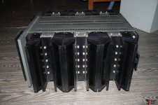
I bought this on a whim, a version 3, KSA-250 that had hum on one channel. It was a 10 hour drive away so I made the deal on the phone and a friend brought it to me on his trip home. Owner said one channel was fine, the other played music but had some hum. I decided to recap rather than power it up first....

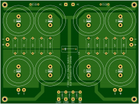
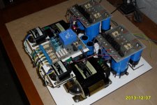
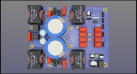
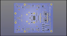
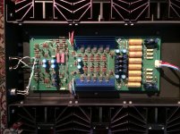
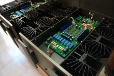
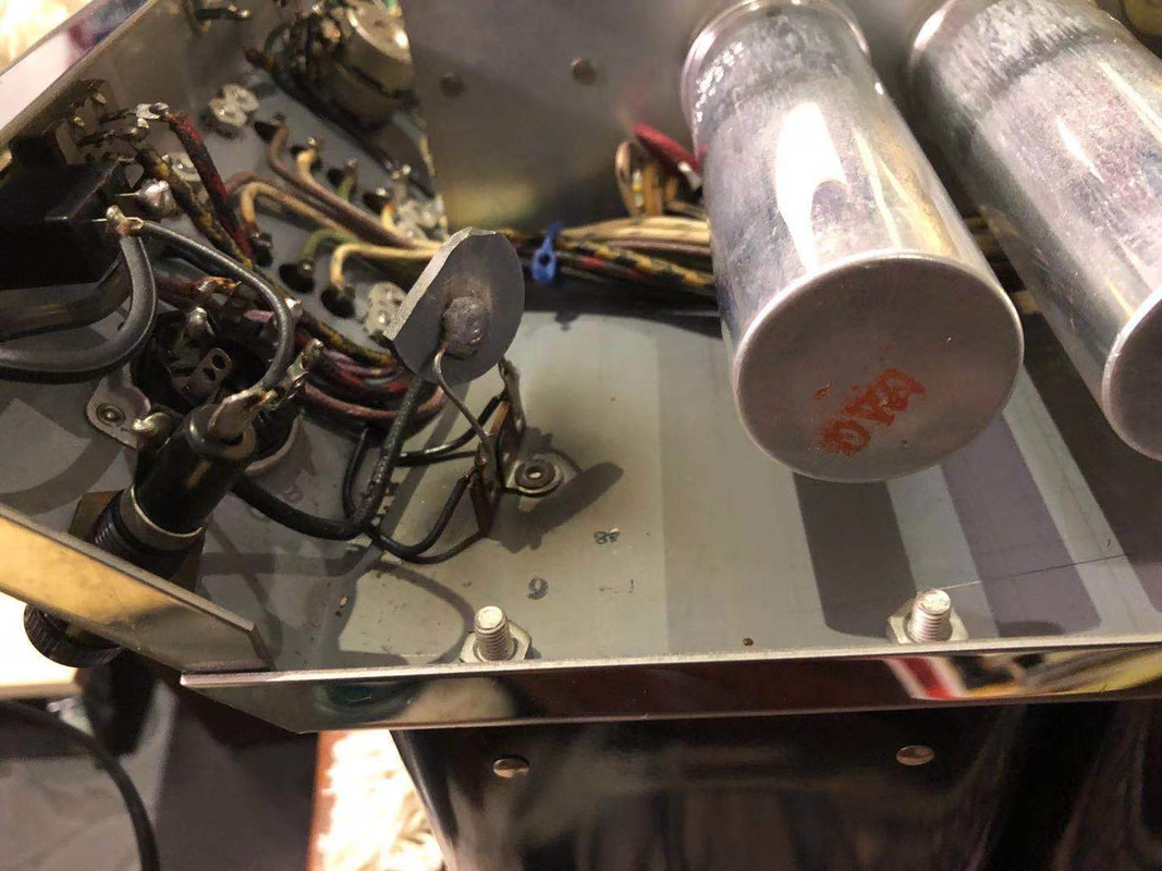
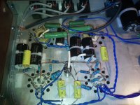
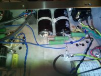
It's a 1995 variation, and had been all recapped EXCEPT for the main power caps, why would anyone pull it all apart and not change the main caps. I thought that would be the issue, easy fix....NOT! When I pulled the cover I discovered on one channel a 1R emitter resistor was missing, and on the other, one was burnt, but still read 1 ohm. I put in a 1R in the missing spot, checked the TO-3 associated with it and it was good. Put in all new main PS caps and powered it up today thinking, ya, it's fixed. Ooops.

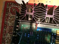
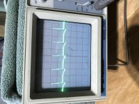
So, I haven't delved into troubleshooting it yet, too dejected, will start this weekend, but just a quick summary of what happens. I have meters on both main caps, one left, one right, when I hit the power button, the front board relays click and I get 80VDC on the right, and 80VDC on the left, but then after about 1.5 seconds the amp shuts down and the left channel immediately dropped to 67VDC, the right channel stays at 80VDC. My initial reaction is well it must be the left channel causing the shutdown as there is current drawing the main caps down, but then the 'ol brain says, wait, no current draw on the right, caps staying at 80VDC, maybe it's the right.

At this point, I unplugged and went for a refreshment. I'll pick it up again tomorrow.

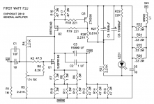
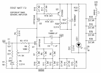
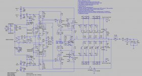
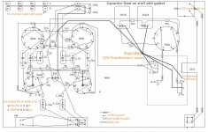
As there are no schematics available, I will be troubleshooting this blind . I am an experienced electronics tech of about 50 years, and fixed a dead ML-332 last year, but I had schematics for that, so I am pretty good at troubleshooting.

Just thought I would get the story out there to be digested by all and hopefully a few ideas pop forward.

Any and all help much appreciated.

Cheers!

Audio System Twister F2-500 no sound output

Hi there guys 😀
Good evening,

Got a defect Audio System F2-500 amplifier, where I'm struggling on for 2 months already.
I've tried several things, but unfortunately I could not find the possible cause of the problem. It has 2 problems.

Problem 1
From left to right, bank 2, 3 and 4 has a potential difference between the Gate and the Source (pin 1 and 3). I fixed the left bank 1, it had bad BCP53 transistors and BC850c and 860c.
On pin 1 and 3 from the output fets (FQP22p10 and FQP33n10) should be the same negative or positive rail voltage. When I installed the fets it went in protect. When the potential difference is gone it doesn't go in protect.
This is a problem, but hopefully I would be able to fix this problem myself after problem 2 has been fixed.

Problem 2
I'm really struggling on this one.
Bank 1 and 2 has absolutely no audio input to the gate of the output fets.
Bank 3 has a sound wave on the gate but the amplitude is 3x smaller than the amplitude from the RCA itself.
Bank 4 has a sound wave on the gate with an amplitude around 10x smaller than the amplitude from the RCA itself.

Photo 1: This is the overview of the amplifier itself. 4 banks of output fets (2 banks per channel)
Photo 2, 3: Photo 2 is the Source of the fets which has the rail voltage you see on photo 3
Photo 4: This is the gate of the fets which should have the same voltage as the Source on photo 3
Photo 5, 6: Here you see the gate of bank 3 with a 100Hz sine wave (3x smaller than the RCA signal)
Photo 7, 8: Here you see the gate of bank 4 with a 100Hz sine wave (approximatelly 10x smaller than the RCA signal)

I replaced all the BCP56, BCP53, BC850c and BC860c transistors from all the 4 banks, I checked all the resistors per bank if they are within tolerance and they are.

Does anyone has an idea?
Thank you very very much for every bit of help!!!! 😀

Phoenix Gold XS2300 Repair

I have an XS2300 BLK that I am attempting to repair. This will be my first repair so bear with me. This amp has had an attempted repair by someone else at some other time.

What I have found so far:

one output transistor is bad (STm IRF540)
one source resistor is the wrong resistance 1 ohm vs 0.1 ohm
one resistor is burnt so bad I can't see the markings but according to 1moreamp in another post it is 324 ohm 1/8w 1% which is connected "across the gate to source leads of the FET".
one MPSA56 PNP transistor case is broken.

I found the parts list from 1moreamp to rebuild the whole channel, so I am in the process of trying to order those parts.

I am having trouble finding the STmicro IRF540, so when looking for a comparable MOSFET from a different mfg. what are the important parameters to compare from the data sheets? It seems like I can match some but not all of the parameters from part number to part number.

Also for other parts it seems one supplier has one part and one might have another resistor other than Mouser, Digikey, what are some suppliers in the US that y'all have had luck procuring most of the parts from one place?

Thank you!

  • Locked
FS: Goldwood GW-1858 18" woofers -in EU

For sale a pair of Goldwood GW-1858 18" Woofers.

Barely used. I bought them to try on Open baffle H frame per MJK recommendation. They both work perfectly.

150eur for the pair + shipping and Paypal Fees.

Goldwood GW-1858 18" Pro Woofer
Goldwood GW-1858 - 18" Open Baffle Woofer
Best regards
Guglielmo
Italy

Attachments

  • pIMG_4552.jpg
    pIMG_4552.jpg
    292.6 KB · Views: 233
  • pIMG_4553.jpg
    pIMG_4553.jpg
    297.5 KB · Views: 241
  • pIMG_4555.jpg
    pIMG_4555.jpg
    214 KB · Views: 234
  • pIMG_4556.jpg
    pIMG_4556.jpg
    223.2 KB · Views: 212
  • pIMG_4557.jpg
    pIMG_4557.jpg
    323 KB · Views: 220

Dynaudio D76 D-76AF - dome midranges - new

Selling a pair of Dynaudio D-76AF dome midranges.

They appear to be new, never used. They were part of a Dynaudio Xennon-3 speaker kit project that was started, but never finished. A friend of friend purchased Dynaudio raw drivers and Xennon cabinets to build these and never finished as he passed away.

The raw drivers were mounted in cabinets, but never hooked up. They may have been evaluated for proper operation before mounting, but connections were never soldered, and only a few show terminal connection marks/scrapes. Thus, I believe they are NOS, never used. One has some dust on the dome, the other is cleaner.

I measured DC resistance of each with Fluke DVM. Each measure 5.2 ohms. I also briefly applied low level music to verify proper sound and no distortion. Both sounded fine.

Selling as a pair. Just as an FYI, I also have the 24W100 woofers and D-28/2 tweeters. Each of these have a sticker labeled "Advanced Akustic" - performance matched to 1% tolerance. These D-76's do not have these stickers, but I wouldn't be surprised if these were closely matched pair as well. The original owner was a pretty detailed guy and huge audiophile.

Asking $425 OBO. Prefer to sell here instead of that auction site.

Actual pictures of my drivers. Message me and I can try to send more pictures if you need them.

I will likely post the other drivers as well at some point. I may use others in project, but I know I won't be using these mids.

Willing to sell the cabinets as well, but I won't ship those. Need to pick up in the mid-atlantic area (Baltimore - Wash-DC). Willing to drive part way if you want to buy the cabinets.

thanks.

Attachments

  • D76-1.jpg
    D76-1.jpg
    485.7 KB · Views: 504
  • D76-2.jpg
    D76-2.jpg
    777 KB · Views: 285
  • D76-3.jpg
    D76-3.jpg
    663.6 KB · Views: 274
  • D76-4.jpg
    D76-4.jpg
    752 KB · Views: 274
  • D76-5.jpg
    D76-5.jpg
    600.2 KB · Views: 267
  • D76-6.jpg
    D76-6.jpg
    587.6 KB · Views: 143
  • Xennon3-a.jpg
    Xennon3-a.jpg
    156 KB · Views: 224

FS - Dynaudio Xenon-3 100 kit

Selling my Dynaudio speaker cabinets. This would be a great winter project for someone that wants to build a high end kit.....

It is an older Dynaudio kit. Xennon-3 - 100. Floor standing version. Black ash finish and black grills.

These were purchased from friend of original owner that planned to build these, but passed away before finishing. He never built the crossovers, so the drivers were mounted in the cabinets, but never hooked up. I removed them to sell and only cabinets are left. There is damping material inside the cabinets as well as rubber Deflex sheets (Cascade Audio) on rear wall of cabinets for diffusion of rear traveling waves from woofers.


No crossovers. I do have the Dynaudio file for these that includes crossover specs and recommended components.

Drivers have been sold.

Cabinets and grills are a little dusty and need some wipe down, but otherwise, they are solid and ready to go.

Inserts in bottom of each cabinet for adding floor spikes if needed.

If sold individually, the drivers alone will sell for $ 800+ in total.

I am asking $ 185 OBO.


**** I have updated pictures. Message me and I can email some to you if interested. Thanks. ****

Speakers are in cardboard boxes, but there is no packing material, nor are they sturdy enough to survive shipping. If they were strapped to a wooden pallet and shipped as freight, they may be fine. Buyer would have to coordinate freight pickup & delivery and payment. Prefer local pickup in the Baltimore, MD - Washington DC area. May be able to meet part way.... can discuss.

Attachments

  • Xennon3-a.jpg
    Xennon3-a.jpg
    156 KB · Views: 740
  • Xennon3-1.jpg
    Xennon3-1.jpg
    53.5 KB · Views: 647
  • Xennon3-3.jpg
    Xennon3-3.jpg
    71.1 KB · Views: 655

Duelund Coherent Audio DCA 16GA Premium Audio Cable - 100M Spools

SOLD

Duelund Coherent Audio DCA16 premium audio cable, tinned copper in cotton, oil impregnated.

One of five spools left. My cost was $410/spool ordered directly from Duelund in the Netherlands, ten spool minimum.

Superior to the famous Western Electric 16AWG hookup wire.

Used to manufacture some of the best sounding speaker cables and interconnects anywhere near the price.

Also great for audio construction hookup wire, rewiring speakers/crossovers, etc.

Retail: $800. Yours for $429/100M spool.

Lengths less than 100M are $6.99/M (7M minimum).

Price is firm. No trades. Buyer pays shipping. PayPal adds 3%. Other fee free options.

Thank you.

Attachments

  • 3060241-cf47b568-duelund-coherent-audio-dca-16ga-premium-audio-cable-100m-spools.jpg
    3060241-cf47b568-duelund-coherent-audio-dca-16ga-premium-audio-cable-100m-spools.jpg
    149.9 KB · Views: 338
  • 3060242-a06e52f2-duelund-coherent-audio-dca-16ga-premium-audio-cable-100m-spools.jpg
    3060242-a06e52f2-duelund-coherent-audio-dca-16ga-premium-audio-cable-100m-spools.jpg
    86.4 KB · Views: 340
  • 3060244-1aa9ae94-duelund-coherent-audio-dca-16ga-premium-audio-cable-100m-spools.jpg
    3060244-1aa9ae94-duelund-coherent-audio-dca-16ga-premium-audio-cable-100m-spools.jpg
    73.3 KB · Views: 338

Newbie w/ questions

Single ended monoblock amp; Is there any practicality or gains to be had by building a separate power supply chassis? There's theoretical advantages in separating power/audio components but in application, is it worth the time & expense?

For a newbie is there any material that works well for prototyping component placement? Masonite, etc? Is it practical to sort components out, build, test then transfer everything to a metal (final) chassis without extensive disassembly and reassembly?

Tube rolling: is it possible to use one transformer with a specific voltage (B+?) for multiple tube types? (6L6, KT-66, 77, 88, 120, etc.)?

Are the advantages of "larger" tubes lost if voltage is not increased?

Thank you!

Pentagrids - using all of them

Has anyone run into a guitar oriented circuit that uses all of a pentagrid?

I've found one circuit (Playmaster PM103) using one as a tremolo modulator, but with a separate LFO. So some of the grids are being "thrown away"

Now basic circuits (modulator + mixer) do 100% modulation of the signal, where as tremolo we'd like to manage the depth. It's too early in the day for me to have a serious think before even contemplating tinkering on a bread board.

In my case I've also got a dual-diode + triode tube, so could use the AM detector diodes to built a compressor.

It's an AM radio chassis (Airzone Cub 458) with 6A8G + 6G8G + 6V6G + 6X5G whose bakerlite is smashed: I can either build a new chassis or convert into something interesting.

On the basis of "there's nothing new under the sun" I thought I'd ask

Philips CD-101?

Hello

Just recently acquired a Philips CD-101 and it sounded very good when first played. So I have modify it by changing various wires and the output cap. The result is quite pleasing as it extended the high and low range of the player...

However, I want to do more extensive modifying of this player... does anyone have any suggestion what to do next?

Also, anyone have a service manual or schematics for the player and CDM1 CDM0 laser head?

Thanks alot in advance!

Attachments

  • cd101c.jpg
    cd101c.jpg
    96.8 KB · Views: 860

Resurrecting a Hafler DH-101 and DH-200

My Dad assembled a Hafler DH-200 around 40 years ago. Put maybe 25 hours on it (mostly by me) at the time. It's been stored away for the past 35 or so years.

I did a visual inspection and sniff test on both units. Both are low time and haven't been powered up in decades. Didn't notice anything bursting, bulging, scorched or leaking.

I built a DBT and borrowed a variac. A few days ago, I began testing/reforming the DH-200. Using a 100 watt bulb, I began at 5% and three times a day since then, I've been increasing voltage in 5% increments.

At about the 30 VAC, the bulb began glowing which I expected at some point. My expectation was that if everything is intact and functioning, that at some point the glow would level off or subside. It hasn't. I am at about the 70 VAC point and the brightness has increased with each increase from the variac. It is an obvious glow but in no way is it bright.

So after days of using a variac and DBT in an attempt to reform the caps, the amp never powered up. So, I then plugged into the house main and ta-daaa... a pilot light.

I re-checked the outlet on the DBT...120 VAC.

I plugged the amp back into the DBT. Half-dim bulb but the amp will not power up.

???

FWIW: when the amp was powered up, I checked VDC at the speaker terminals (DC offset?)

L: 80 mV
R: 160 mV

The DC offset measurement was just something I jumped on because it was a quick and easy to check. Since the DBT didn't pan out, should I be looking for something else that could be wrong with the amp?

Thank you.

Sony HCD-XB4 hifi help

Right I made a big mistake the other night with my sony hifi model HCD-XB4 I accidentaly shorted out the right channel while doing a little experiment with vu led's meter's the protection relay kicked out but did not switch back on I made a bad choice by manually switching the relay back on by bending the contacts I know idiot move🙂 but there was a loud hum on the right channel but still sound now there is just a loud hum on that channel and no sound please what did I blow and how can I fix it this hifi is 25 years old and I don't want to get rid of it I really like it

NAD C340 no input switching.

Hi Folks

A customer has brought in a NAD C340 amp where none of the input selector buttons work or their corresponding leds.

I did read:
https://www.diyaudio.com/forums/solid-state/91538-nad-c340-input-selector.html

and also googled the problem.

This lead me to believe that the switching IC maybe faulty. I have replaced the switching IC and the problem persists.

I have tested the new IC. Pin 1 is ~16-17 V- and pin 28 is ~16-17 V+.

I have tested R.H. channel inputs(pins 18 to 27 of the I.C.) and get no voltage. I tried L.H. channel inputs on the other side of the IC and got the same result.

I think Q702 IC on the "Display PC Board (NADIS-6365)" is faulty. I have looked at the service manual and the input selector buttons do indeed first connect to Q702. Q702 then turns the button press into 128-bit or 256-bit serial data.

The datasheet for the switching IC (TC9273N) says: "The switches are set to ON or OFF using 128-bit or 256-bit serial data."

Is there a way to confirm which IC is faulty?

I think the new switching IC (TC9273N) is fine, because it is getting power; but its not doing anything because it's not being sent serial data by Q702.

Chinese pre amp kit

Hi all.
I built this and have triple checked it with the schematics.
I first tested it with a sinewave and monitored it on my scope and got good wave forms on input and output . So I tried connecting it to my Philips ag9016 which it double insulated and with the vol on pre down no problems.
As soon as I turn up vol I get hum .

On inputs I used the shielded cable that is connected to input ground on the sockets that are isolated from chassis . The ground shield is not connected at the points the cables go to the 4 way selector.
The ground on shielded cable that go to output are grounded.
Any ideas
Thanks

Attachments

  • 1.jpg
    1.jpg
    303.4 KB · Views: 111
  • 2.jpg
    2.jpg
    211 KB · Views: 124
  • ee.jpg
    ee.jpg
    158.1 KB · Views: 104
  • sch.pdf
    sch.pdf
    155.7 KB · Views: 98

Vifa TC9FD18-08 best bang for the buck

Hi,

Measurements shown here and elsewhere suggest that the Vifa TC9FD18-08 currently seems to be the best bang for the buck. Far better performance than drivers that cost a lot more.
Transducer Detail | Tymphany

Like any small driver it starts to distort at low frequencies and is limited in output though.

In what type of enclosure would the driver work best if paired with a subwoofer? The goal would be to achieve low frequency extension to about 80Hz. What SPL can be expected?

Is this even a viable option or would a FAST configuration be a better fit?

Sparkler model S512 "perceive" DAC

I received this DAC from Victor last Thursday. The presentation is clean and tonally accurate. It is PCM/Red Book only and CD's sound wonderful. I got caught in the SACD hi-rez game 20 years ago and am no longer interested. We spoke on the phone and Victor won't be getting more Sparkler Gear until EMS service is available in Japan again. FedEx has a $300 surcharge. 😱

I've been a tube guy for a very long time but I will get a Sparkler Ether integrated amp when EMS is available.

Thanks Victor. :up:

suggestions for new phono stage

Hi everyone,

I'm interested in building a new phono preamplifier for my stereo. I'm not sure which model to make, and I'd be very grateful to hear your suggestions.

A few bits of possibly relevant information:
  • I'm using an old Luxman PD277 turntable. Works great.
  • The Luxman gets plugged into a Schitt Mani, then into an Onkyo integrated (used as a preamp), and tape out to a Tubelab SSE (as poweramp). My speakers are Tekton Lore.
  • I've been using 2 cartridges recently: a Grado Prestige Black (v3, I believe) and an AT vm540ml.
    • I like the warm sound of the Grado. Zeppelin never sounded so good. At some point, I might get the Gold version
    • I like the detail of the AT. I can hear a lot of the nuances in jazz records
  • The AT cart sounds a little ... bright? it's not unpleasant or shrill, and you can definitely hear the bass very clearly. It's just voiced kind of on the highend for me. I understand this could be b/c AT carts are very sensitive to capacitance in the phono stage, and I don't know what the capacitance of the Schitt Mani is, nor whether the captive RCA cord on the Luxman is low capacitance.
  • I listen to a pretty wide variety of music: rock, jazz, country, my kid plays imagine dragons...

So I'd like a phono stage that is low (zero?) capacitance. It could be adjustable, but it's not that important b/c, as I understand it, the Grado carts don't care about capacitance. I don't have a preference for tube vs. solid state -- whichever produces good sound. I've built some amps (Tubelab SSE, Starving Student II headphone amp, Fender 5e3 clone) so I have a bit of experience and am good w/ a soldering iron. But I'm nowhere near being able to look at a schematic and just go from there. I don't need a kit, per se, but a BOM and a bit of guidance/documentation of the build process is important. Lastly, cost isn't too much of an issue. I don't think it would make much sense to spend +$1k..., but I would like to have a great phono stage at the end.

I'd be very grateful to hear your suggestions!

Thanks,
Dan

Vented box WinISD issue

Hi all. Please don’t hammer me for not searching for this. I can’t seem to find something answering my specific question.

I’m trying to model a ported enclosure with WinISD. The problem is the port velocity and first resonance usual issue

Question is when I tell WinISD that the port will have 2 flared ends, nothing changes. Velocity and length stay the same

I don’t know how long to male my ports due to the flared ends. I know this alters the length needed.

And more
Importantly what port velocity can I go up to and how much does the flared ends help.?

And do I need a specific flare size?

Plans are as follows

Alpine swr1542D
140litre box (solid rosewood tv cabinet) with added 18mm mdf on all sides)
Tune to 19 or 18 hz
External port in order to achieve adequate port length

Any other pointers I should consider?

Thanks in advance

New speakers

Hello,
I want to build a new pair of speakers.
I will use this speakers, because I already have them from other projects:

- Tweeter : 27TBCD/GB-DXT H1499
- Mid woofer : SB17CAC35-4
- Subwoofers : SW26DAC76-4

The design will be like the one in the picture (Barefoot Sound )
Subwoofers on the side
Amplifier with DSP : Hypex FA503

Attachments

  • barefoot-sound-micromain35-gen2-monitors-pair-cf9.jpg
    barefoot-sound-micromain35-gen2-monitors-pair-cf9.jpg
    230.1 KB · Views: 630

Yamaha HS8 or DIY build ?

My brother's children are enthusiastic young musicians, and he has a music room in his house. The kids have asked for the ability to play amplified keyboards, guitar, sing, etc... so he has acquired a second hand mixing console, a condenser mic, some other equipment. What he needs now is speakers.

His local music shop has a pair of lightly used Yamaha HS8 powered monitors for $500/pair. They are recommending this to him.

He already has several amplifiers which would work fine, so he does not need active speakers.

He recently built a Paul Carmody design for his home theatre setup. He asked me if he could build a better pair of passive speakers for $500 than the Yamaha HS8.

I do not know what to tell him. I know that music instrument and PA equipment is a very different kind of requirement than hi fi speakers. But when I look at the HS8, it seems like a rather conventional 8 inch woofer and 1 inch dome tweeter.

All thoughts are welcome

Jim

Tweeter design change from 5 to 8 Ohm

Hi

I am going to build a speaker designed by Paul Kittinger called "canTiLena".
I finally purchased the scanspeak speakers, takes a while to find $700 disposable funds.

Any how this design is over 10 years old and I cannot buy the original specified ribbon tweeter for it ( Fountek NeoCd1.0 1.5", Fountek does now make a new model of this tweeter (Fountek RD1.0 Ribbon). The problem is the old model was 5 ohm and the new one is 8 ohm.

Which leaves me at a fork in the design road

1: ignore the 3 ohm difference in the tweeters
2: modify the crossover resistor to adjust from 5 to 8 ohms
3: find a similar Tweeter brand that is 4 or 5 ohm.

My electronics knowledge is just enough to be dangerous, so I really would not know how to recalculate the resistors, maybe someone here could help.

Thanks in advance for your advise.

Selling my TSE

I am selling my amp. It is working perfectly and has some very nice parts. Electra Print choke and output transformers. Edcor power transformer. ClarityCap MR coupling cap. Vishay nude input resistors. Dual 40uF motor run caps. Cardas speaker posts and RCA's. Combo of Elna and Nichicon caps in specific areas. Built on a custom mahogany base. Aluminum plate has been bead blasted to give a frosted look. I will be posting pictures when I can figure out how to do that using my Chromebook. I posted some pics on a show us your amp thread a few years ago. I have a bunch of tubes to go along.
Walter Roman
Carlisle, PA
301-938-9260

Haufe t42 SUT as I/V for TDA 1543

Hi there,

I do have a pair of Haufe t42 transformers laying around and i would like to use them to perform I/V conversion on a I2S dac with a single TDA1543 i also have on my shelf.

For what i have found in internet these transformers do have a 1:20 ratio.
I measured the windings :
primary @ 3,8 Ohm
secondary @ 3,1 KOhm

Can someone please help me out with calculating Rsec value for a setup like this:
DAC.jpg


I'm simply too dumb to do it and after reading tons of posts on forum and articles on internet I'm totally lost.

I really will appreciate help of someone who is smart,

Best Regards

Bartek

Transformerless ultralinear?

Hi everyone.
I've come across this concept on tube cad journal:


The Tube CAD Journal,Ultra-Linear Output Stages

Basically, a scaled down anode voltage is feed to the screen (or cascode's upper triode's grid).

AFAIK, this is not ultralinear. Ultralinear is something in between pentode and triode. But just supplying a scaled down voltage to the screen grid makes the triode even more triode.


I hope that the attached simulations show clearly what I mean.
For the "ultralinear" simulation I gave E1 source a value of 0.43 instead of 1.
In that case, the curves are lower than for pure triode.

Am I doing something wrong here?
Thanks!

Attachments

  • schem.png
    schem.png
    9 KB · Views: 507
  • el84 triode.png
    el84 triode.png
    50.5 KB · Views: 508
  • el84 43% screen.png
    el84 43% screen.png
    30.9 KB · Views: 496

AD797 not sounding good

I dropped in some AD 797 into an Adcom GDA-700. Circuit diagram attached - see page 4.

I recapped the unit and added 100uF Silmic and 0.1uF MKP bypass to all V+ and V- pins.

In short, it doesn't sound that great. I put some OPA627 in a similar unit last year and Frankly the 627s smoke the 797.

I know the circuit implementation of the DAC is probably not ideal for the AD797. Any suggestions on simple changes to make this work?

Attachments

PP EL84 Problem (HELP)

Hi,
I've built one channel of this amp PP El84
Schematic.JPG


It sounds very fine, but I've a strange problem:
I noticed by observing the woofer that the cone "breathes" (this term is not very technical but it gives a good idea), that is, it oscillates slowly with a constant excursion of 2-3 mm with a very very low frequency I would say, by eye, about 1 cycle per second (1 Hz) but no noise comes out of the speaker. I measured the output with the multimeter and there is a voltage that fluctuates, between 0 and 200 mV.
Some ideas on possible causes?
Thanks in advance to those who want to help me.

Fuse holder for secondary windings and HT rails

I'm building a very classic 50W class AB power amp in metal chassis.

How do you mount fuses on secondary windings and HT rails of a PSU?
I refer for example to Randy Slone's circuit at p.317, fuses F2 to F7.

Do you use in-line fuse holders, or some sort of buss blocks to be screwed on chassis like in car-audio?

Attachments

  • 20210207_144652.jpg
    20210207_144652.jpg
    742.8 KB · Views: 98

Shallow and angled home-made speakers

I made this topic to show my first home-made speakers. I came to this project because the form factor I had in mind can’t be bought. Since I didn’t have any experience with building speakers, I took a second-hand pair of my favourite speakers: the Hepta Gem. It’s a Dutch brand. I re-used the drivers, the crossover, the bass-pipe and the dampening material. And I could take it’s internal volume of 9 Litres as a reference.

aY0qiZTDIq97EMUzNt2xnVAy.jpg


Then I started drawing in the program Geometry Expressions. This is a frontal view and a cross section.

oml4NL0P5dMc7NeMU0Mo3554.jpg


yIHrBeRmfYgwB1XnClGDtJL0.jpg


The speakers are 50 cm high, 35 cm wide and 7 to 16.3 cm deep. That’s about 20 inch high, 14 inch wide and 2.8 to 6.4 inch deep. The front is angled 15 degrees towards the listener, since I listen to them sitting very close to a wall behind my electric piano.

I used 1.8 cm (0.7 inch) thick multi-ply:


3HLfL0J7TXWfMqmaFPBeuGOI.jpg


When trying out my speaker, it didn’t sound very well. It turned out the multi-ply was vibrating quite a lot. This could be fixed by adding some reinforcements and self-adhesive vibration dampening material:

r4k9egd00eGflgoQio5vZOYt.jpg


Because of the 15-degree angle I couldn’t use clamps and ended up using 75 temporary screws for each speaker to tighten the glue joints. I later filled these holes:


ksj7m4lZpvFXqKBwLGsstpue.jpg


The end result without the speaker-cloth was already quite to my liking:


Mtb1Sl6Oe93gKTpCA2AOT2hJ.jpg


qPSBePw1yQVX8r49B0gkrvro.jpg


For the speaker-cloth I made two wooden dodecagons (twelve-sided polygons) with a 45 degree angle on the sides.

The best way to attach the speaker-cloth turned out to make grooves with a multitool, fill these with glue and then push the speaker-cloth in the grooves. This way the speaker-cloth can be mounted without worrying the glue isn’t dry enough yet to hold the tension.

mhhrOqnmaKCJhK902ZQLIWyn.jpg


eEidKZCE5vPbymjcB8q5a3jv.jpg


GRB9q3ec1pRMqhAmMQXCpkxe.jpg


This is the end result.

xXZVltI4gDtqieuhth8OF8l8.jpg


Large image

XMF5AQCeL61NIoZFBze45O5T.jpg


Large image

  • Locked
FS: FIRST WATT F2/F2J PCB + PSU

Up for sale is a set of 3 PCBs for Nelson Pass FIRST WATT F2 and F2J (only 4 sets available):

left channel + right channel + power supply.

I’m not going to prepare the BOM file, but below are the details that should help to choose elements by yourself, I have also attached the schematics.

CAPACITORS:
C1A - grid: 2.5mm, diameter: 5mm
C1B - grids: 5mm, 7.5mm, 10mm, 15mm, 22.5mm - max width: 10mm
C2 - grids: 10mm, 15mm, 22.5mm, 27.5mm - max width: 13mm
C3, C4 - grids: snap-in 10mm and 7.5mm THT, max diameter: 23mm
C5 - grids: 15mm, 22.5mm, 27.5mm, 37.5mm, 52.5mm, and the last one around 56.5mm, max width: the width of the board actually, so 55x40mm should fit here.
C6 - grids: 10mm and 15mm - max width 6.4mm

RESISTOR:
low wattage resistors:
grid: 10mm
max diameter: 2.8mm
max wire diameter: 0.8mm

power resistors:
grid: 17mm
max diameter: 6.3mm
max wire diameter: 1mm

Please note that Z1 and R2 are only used in F2 (when IRFP240 is used instead of SJEP120R100 as Q1)


The PCBs are made of standard fiberglass epoxy laminates FR4 with the standard 1.6oz/ft2 thick copper, hot air solder leveling with lead - BTW I am using the soldering tin 60/40 for my projects and I don't use RoHS Pb-free crap tin with silver. The high current paths are 115mil on both sides. The path between MOSFET drains is double 150mil, so the temperature at idle current of about 2A rises only 0.11°C above the ambient. The track clearance is 0.8mm (31.5mil), which's enough for 24V according to the standards.

The power supply board:
size: 160.2 x 120.2 mm
mounting holes: 150 x 110 mm

Please pay attention to R9 and R10 resistors on the PSU board marked with *, these aren’t 0R47, using these will definitely cause a short circuit, these are 2.2k.


The amplifier boards:
size: 279.5 x 39.5mm
mounting holes: 270 x 30mm

- the center mounting hole is 140mm from the hole located at the edge.

The mounting holes are 3.2mm for M3 standoffs located at the multiplication of 10mm, so it's possible to mount them at the grid with the same grid of holes – like in modushop.


PCB are going to be ready for sale from 20 Februrary 2021.


The price is $29 per set + shipping.

Attachments

  • psu-pcb.png
    psu-pcb.png
    242.8 KB · Views: 523
  • f2-pcb-a.png
    f2-pcb-a.png
    141.6 KB · Views: 507
  • f2-pcb-b.png
    f2-pcb-b.png
    141.5 KB · Views: 501
  • F2J-schematics.png
    F2J-schematics.png
    34.7 KB · Views: 585
  • F2-PSU-schematics.png
    F2-PSU-schematics.png
    176.5 KB · Views: 550
  • F2-schematics-r1.png
    F2-schematics-r1.png
    142.9 KB · Views: 308

  • Poll Poll
How much did you spend on your last audio-related DIY project

How much did you spend (in USD) on your latest audio-related DIY project?

  • Less than $50

    Votes: 2 10.5%
  • $50-99

    Votes: 0 0.0%
  • $100-199

    Votes: 2 10.5%
  • $200-299

    Votes: 2 10.5%
  • $300-399

    Votes: 3 15.8%
  • $400-499

    Votes: 0 0.0%
  • $500-999

    Votes: 6 31.6%
  • $1000-1999

    Votes: 2 10.5%
  • $2000 or more

    Votes: 2 10.5%

I'm doing a little business planning, so I'm curious about how much people spend on their DIY audio projects.

How much did you spend on your latest audio-related DIY project?

Tom

Stupid Mistake with F5 Turbo - Advice Needed

I recently finished both of my F5 Turbo monoblocks other than installing the power switches, which hadn't arrived yet. They were working, i.e., playing music, and I had them biased close to where I wanted them.

The power switch I am using has a LED unit that that is 12V AC or DC, so I decided to use the 12V secondaries from my transformer, which I was not using for anything else.

The issue I had is that the Antek schematic for my transformer appears to have been wrong, because the two orange wires that were supposed to be 12 V, were different secondaries. My transformer has 12V and 18V secondaries, and the schematic said the two orange wires were the 12 V, but it turns out one orange and one brown were 12V and the other orange and the other brown were 18B. No idea why.

Anyway, I mis-wired the switch and after powering up the amp, all sorts of weird **** happened in the few seconds before I powered it down. There was definitely a sound and burning smell of some sort, which I can't find on any of the boards, but I assume was the LED unit burning out.

So I disconnected the switch altogether and started up with a dim bulb tester, and the was initially pleased because the bulb dimmed. But then I noticed that the LEDs on the power supply board were doing something odd. Previously, when I powered down, they would both stay on for a fairly long time. Following this event, one (on the negative side) would fade out pretty quickly.

So I disconnected the other PCBs from the power supply board, fired it up, and it seemed to work fine. Both PCBs stay lit, the voltage is constant at 41/-41 on each side, and I see no issue.

Plugged the PCBs back in and same issue. So I'm assume there is a short or some issue somewhere. I started with the main board and checked the two transistors and the Jfets, and all were fine. Before I disassemble anything else, I wanted to get some advice on how to potentially find the problem without just going part by part.

Not an engineer by training, so please excuse my stupidity. I guess it's good that I love this hobby even when **** like this happens.

Thanks in advance.

Preamp output - SE to balanced choices?

Assuming you have a simple single tube SE stage in a preamp, what are all the possible ways of converting the SE output to balanced/PP?

- transformer
- concertina
- mosfet splitter
- other?

What are the advantages and drawbacks of these various solutions? There's also going to be a cost differential between valves/mosfets and a good output transformer.

Schematics would be very welcome as illustrations of the different methods.

2nd amp from scratch: Low NFB- FET front end - BJT OPS

Dear Diy'ers,

I'm feeling confident enough about the current state of this amplifier design to show it to you guys.

Please have a look into the attached document. I've tried to put all information into there including links to other threads. To encourage some interest I've attached already some pictures

This amp will be build, only it will take some time. I also have to put some time into my family offcourse (daugther of 1year old).
My previous amp kept me busy for about 1.5year.

If you guys see some opportunity's to make it better or if there are remarks, please let me know!

Attachments

TPA3255 Troubleshooting

Hi all,

I have been working on a TPA3255 project for a while now, and already have some of my boards up and running but i am experiencing that the boards are clipping really soon. The design is more or less based upon the TPA3255 EVM with Post-Filter Feedback circuit and pcb layout is inspired by another project on diyaudio. I am only able to get 22vpp out of it on both 4R and 8R loads while running at 48.5v before it starts to clip, however by raising the voltage to ~57v i was able to push it to 25v before clip. The sound of the amp before it clips is amazing, very clear and open.

PCB have a cu thickness of 2oz, attached is schematic used and front/back pcb.

What have been done so far to eliminate where the issue is located,

- Bypass entire input section, and attaching a separated balanced buffer directly before R_in. Same result
- Switch from 4ohm to 8ohm load. Start to clip at same output voltage, so it does not seem to be current related.
- Switch OC resistor to 30k, instead of 22k. Same result
- Different PSU, Same result.

Tomorrow i will remove the heatsink and solder cable directly on to TPA3255 in order to measure its input voltage in case of defects on the PCBs.

I would like your inputs on this, maybe there is something i cannot see.. 🙂

Attachments

  • TPA3255.jpg
    TPA3255.jpg
    232.2 KB · Views: 347
  • TPA3255_back.jpg
    TPA3255_back.jpg
    262.3 KB · Views: 296
  • TPA3255_back2.jpg
    TPA3255_back2.jpg
    263.7 KB · Views: 298
  • tpa3255_schmatics.pdf
    tpa3255_schmatics.pdf
    470.6 KB · Views: 170

Krell KRS-100

Just bought a pair of Krell KRS-100 Class A fixed bias amps from around the year 1992. They look somewhat similar to the bigger PassLabs designs like the XA-160 which are Class A fixed bias amps also.
After extensive search on the Internet and trying to contact its designer Dan d' Agostino I got nothing apart from a measurement report from a German technician that mentioned they deliver 236 Watss @ 8 Ohms and 426 @ 4 Ohms with 1% THD and "very harmoniously falling harmonic distortion" whatever that means.
I wish to adjust bias and offset (I know which trimmers I have to use) but I have no data, diagrams or service-manual. Now they take around 600 Watts from the AC outlet and they're not quite similar in surfacetemperature.

A user from this forum told me regarding a KRS-200 that this design consumes 7 Amps of bias to reach his 4 Ohm rating all in Class A.

Sadly Dan d'Agostino was not willing to help me and said I should contact his former employer Krell Industries which I maybe will but I do not expect anything from them either.

Nelson Pass helped me a bit out as generous he always his with sharing his knowledge even about his former designs like Threshold, but I feel a bit inhibited to bother him to much about designs he did not craft.

The first three pictures are from the actual unit the last two from the Internet.

Maybe someone can point me in the good direction.
Thanks in advance.
https://www.diyaudio.com/forums/attachment.php?attachmentid=918623&stc=1&d=1612427111

https://www.diyaudio.com/forums/attachment.php?attachmentid=918624&stc=1&d=1612427111
https://www.diyaudio.com/forums/attachment.php?attachmentid=918625&stc=1&d=1612427111
https://www.diyaudio.com/forums/attachment.php?attachmentid=918626&stc=1&d=1612427111
https://www.diyaudio.com/forums/attachment.php?attachmentid=918627&stc=1&d=1612427111

Attachments

  • IMG_2973.jpg
    IMG_2973.jpg
    626.1 KB · Views: 886
  • IMG_2983.jpg
    IMG_2983.jpg
    753 KB · Views: 661
  • IMG_2960.jpg
    IMG_2960.jpg
    554.2 KB · Views: 648
  • 2078655-1-krell-krs100-monoblock.jpg
    2078655-1-krell-krs100-monoblock.jpg
    120 KB · Views: 625
  • KRELL-KRS100-COPPIA-extra-big-26236.jpg
    KRELL-KRS100-COPPIA-extra-big-26236.jpg
    190.7 KB · Views: 894

Load balance in simple long-tailed pair?

Hi all.


This may see like a newbie question, but the search feature returns nothing (for me anyway).


In a differential pair where the load is not a current mirror and when only one output is used, designers typically do not put a resistor at the unused side's collector (see attached image, left).


Is there anything to gain by having the same load for both transistors (see attached image, right)? After all, when a current mirror is used, both transistors are loaded equally.


Any insight would be appreciated! Cheers.


--Christian

Attachments

  • SimpleLTP.jpg
    SimpleLTP.jpg
    650.8 KB · Views: 268

Best OPT for use over 400 HZ

Hi All.

I have recently completed building a pair of horn loaded two way speakers with a split crossover. The crossover is split into HF and LF sections so that one amp is used for the lows and another is used for the highs. The crossover point for this amp is 630 HZ.

My 630 HZ crossover point means that the amp driving the HF section of my speakers doesn't need to be able to put out bass frequencies. Given this fact, what are the optimal characteristics of an OPT for this HF amp?

I build tube amps, so there is no issue with building an amp that has the limitation of working only above 400 HZ (400 HZ rather than 630 HZ because I may want to use it in another 2 way that has a 400 HZ crossover). I am hoping that being freed from the requirement of having to reproduce bass frequencies will create an amp that has better mids and highs than would be the case for a normal full range amp.

The other side of this question is what would be the optimal characteristics of an OPT made for bass frequencies only? Say 400 HZ and below.

My understanding is that the parameters that make OPTs great LF performers are in conflict with the parameters that make them great HF performers. My thought is that my set up allows me to split these opposing requirements into two separate amps.

I know that this is an odd question, but any advice or input would be much appreciated. Also appreciated would be any recommendations for specific OPTs that fit these criteria. Thanks!

No sound from left channel - TA2024

Hi everyone !

I have a problem with my Sure-TA2024 amplifier. After i returned from vacation my left speaker had no sound 🙁
I disassembled the unit in hope of finding a simple loose wire, but nothing.. Tried a new sound source, new sound cable, switched speakers, connecting the speakers directly to the board, nothing works. Only the right channel.

Any ideas, before buying a new one ?
Here's a picture of the board:

An externally hosted image should be here but it was not working when we last tested it.


Regards ! 😉

Heat sinks query? Design there-off

Thinking about making an amplifier and while I have a collection of heat sinks here the biggest are from 200W amps and I may need something much larger.

If I was to assemble a heatsink from bits and pieces I have around is there a design calculator that is usable for vertical tunnels as I have read that vertical tunnels are more efficient than horizontally finned ones.
Is this true?

I have the large heat sink in the pictures attached but running the calculator over at Rod Elliots sound pages I get a figure of approximately 0.14C per watt which might be marginal for the power I want and need.
I want 300 watts and stereo so I would need to dissipate 600 watts from the single heat sink.
I had an idea to fit this amplifier into an old computer case I have in the shed

Attachments

  • IMG_1745.JPG
    IMG_1745.JPG
    130.6 KB · Views: 99
  • IMG_1748.JPG
    IMG_1748.JPG
    128.3 KB · Views: 110

Rockford Fosgate Punch 60ix

Bought this amp untested and of course it arrived DOA. Power supply fets (IRFZ44) had failed and although I’m not reading any shorts on the output mosfets I can tell one has definitely been replaced so it has had a failure at some point. I am trying to determine if the power supply drive circuit is intact. If I apply just remote and ground the power supply gate drive signal looks close to what I would expect

iCloud

Based off of that I dropped in a new set of IRFZ44’s and it powered up without drawing excessive current and idled with no issues. Rail voltage looked good and there was no excessive DC on the outputs. However the gate drive signal looks a lot different now unless I drop the input voltage to about 12.2 volts and then it looks like what it did before the new fets were installed. Here is what it looks like with about 14.2 volts of input.

iCloud

It’s been a while since I worked on an amp. Maybe this isn’t a big deal. I only remember seeing this one other time but the PWM chip in that amp was an SG3525. Just wanted to run it by the pros before moving forward with trying to find new outputs for the channel that has been worked on previously. I’d like a matching set of outputs in it.

Attachments

  • 44C05098-0CE4-49FB-8814-B55FEC72EEB8.jpg
    44C05098-0CE4-49FB-8814-B55FEC72EEB8.jpg
    909.3 KB · Views: 76
  • E82258B0-0EFD-4017-888D-6A2D56B47E97.jpg
    E82258B0-0EFD-4017-888D-6A2D56B47E97.jpg
    983.2 KB · Views: 71

JBL AVR 101 SMPS Troubleshoot

Hello Everyone, i am new to this forum as well as audio repair. This is my first time trying to troubleshoot and if possible than repair my AVR myself. My AVR power led start blinking when I switch it on. I have removed the SMPS and checked the voltages. I am getting only +/-22V which is supposed to be +/-45V. All other voltages are ok. +/-45V goes to AMP pcb. I have visually inspected the SMPS pcb but I could not find any problem. Can you guys please suggest what can be the problem in this case? If required i can share schematic of SMPS. Thanks.

Noobie question about data sheet max plate voltage

Hi,

I just breadboarded the input 6J4 stage of a Pete Millett design, not for that project but just to copy his operating points as a start my Darling amp...

Here it is, only the 6J4 and its plate and cathode resistors pertain Pete has a lot of optional features for this board:

Push-pull driver board

He's running a 6J4 with B+ of 293V, plate resistor of 30K and a Rk of 1K. As you can see he measures 190V right at the plate. I did the same lash up with 293V B+ and came close at 185V at the plate (slight resistor differences). Pete measured 3.4ma, I'm pretty much the same measuring across the plate resistor I get about 3.7ma. The tube grid is grounded. OK all is good, we match.

Then I went to go read the data sheet for 6J4 and it says that the max plate voltage is 150V!

https://frank.pocnet.net/sheets/049/8/8532.pdf

Finally my question is... Is the data sheet max plate voltage a hard stop or does it pertain to something entirely different? I'm confused as to why Pete Millett (a tube god) has 190V on the plate when this tube says 150V max on all data sheets.

Its more likely I probably have a big knowledge gap learning 🙂

6J4LashUp.PNG

6J4LashUpData.PNG
Projects by fanatics, for fanatics
Get answers and advice for everyone wanting to learn the art of audio.
Join the Community
507,803
Members
7,889,056
Messages

Filter

Forum Statistics

Threads
406,270
Messages
7,889,056
Members
507,803
Latest member
Wynton87