JVC PC-X1000

Just bought this boombox the Other day

5CyFsW9.jpeg


Its from the year 1990 i think. The boombox has a power out put of 70w 17wx2 and 36w to the sub. However tape deck A doesnt fast forward or rewind and the cd changer doesnt recognise that there are discs in the cartridge any idea what it might be? Ive tried cleaning and tweaking the laser and have changed the spin motor out. When you load a disc and hit play the disc doesnt even try to spin and it has me puzzled. Any help would be appreciated. Also does anybody know if there are any boomboxes that are more powerful just out of curiosity. Ive heard on other forums that were are old yamaha boomboxes that could destroy the 1000 but when i looked them up i couldnt find any with as high outputs. Ps half of the pictures didnt upload but im too lazy to go back to try to upload them again

Wiring for fullrange drivers?

Hello everyone. I am posting a topic that has been long debated over and over again. I am posting to get some ( hopefully down the Earth answers ) about some wire brands I am looking at using? Or share what you have used and how it has worked in your system? Here are a few companies I am looking to buy 12 gauge wire from?

1. Mono price wires? They have mixed reviews about the grade of copper they use?

2. Gotham Cable. It's good cable and it works. Ask Mr. Pass labs.

3. Canare Cable. It's good Cable and some think their focus on twisted shielding hurts the sound?

4.Sommer Cables. Not much about them but their catalog they send me is huge.

5. Nvx and knukonceptz they look amazing for the 12 guage wires? They are priced well but, are they worth it?

6. Jsc or Carol or sewell wires? Not much about them or anyone using them?

These are the speaker wire companies am looking at using for my speaker system. Tell me what you think? Thanks Jeff

AMC CVT3030

Help with B+ supply mod (gyrator?)

Dear community,

A few years ago, I got my AMC CVT3030 amp modified. One of the modifications was along the B+ supply to the tubes (gyrator?). While the acoustic result was very good, the execution of the mod, as you can see in the picture, was outrageously sloppy if not dangerous, to say the least.

Recently something got wrong with it while I was re-soldering a few shaky spots. Now I do not know how to fix this masterpiece which contains also some random components just hanging loose (!!!).

So I am thinking of reviewing and rebuilding it, possibly with your help.

I am attaching a schematic I drew just by inspecting the piece of junk. As you can see in a couple of spots I do not even know if there is a connection or not. In the schematic I also included the large capacitors at the input (from the rectifier bridge) and output (rated 450V and 400V respectively).

Since this circuit is intended to provide a clean supply to the tubes I could also explore the alternative, possibly easier to implement, to eliminate the old mod and add the following Tentlabs module> Electronic Choke

What do you think? Would it be worth to try rework the old mod into a new one or just go with the Tentlabs module?

Thanks very much
Fabrizio

Attachments

  • schematic.png
    schematic.png
    12.6 KB · Views: 708
  • IMG_3173.jpg
    IMG_3173.jpg
    592.4 KB · Views: 671

Laser Diode always on

Hello Everyone,

I have bought a used CD-Player from Ebay and Onkyo C-733 to match it with my Onkyo R-N855. The CDP sounds gound enough for me and purposes.
It arrived in mint conditios. It also sounds much clearer than my other CDP.

Anyway what I wanted to discuss is actually following:
When opening, taking the lid off, the CD player for inspection I have noticed that the laser diode will never switch off when the device is on. Is this normal with this machine?

All my other CDPs did switch the laser diode off when no disc was recognised.

Any suggestions?


-Best

Dutchvan

JBL recone

Hello to all on this beautiful Valentines day. I hope you all are enjoying the company of another! However, lol... I have a question to interrupt your festivities. I'm sure this question has been asked... Owning a pr. of JBL 2205J woofers, I wanted to know of anybody taking any 15" frame and having it re-coned to match a different model's spec.? Turning a 2205j into a 2226H for instance...? Is this possible and to what success?

kingfisher

Lesser of two evils for TPA3116 input caps : 0805 ceramic or foil with wires

I’ve got this dayton dspb-250 amp and the sound is... worse than the other 3116 amps in my pile here.

I’m trying to do some upgrades, the input caps are 0805, but i’d like something better (and smaller capacitance). There’s no way to mount the smd version of the wima mks-2 caps i was looking at without putting them on a small board nearby with some flying leads. My instinct is that this is probably still better than the stock ceramics (of unknown value)

It doesn’t look like any film caps are small enough to fit 0805 (i could maybe squeeze 1206), even at the small values of .47-.22uF that i’m looking for.

Does anyone have experience with this problem? Are there better caps in the 0805 size or should i just use the through hole caps with wires...

Attachments

  • 6DCC906B-3CBF-4D00-AF07-230695542B5B.jpg
    6DCC906B-3CBF-4D00-AF07-230695542B5B.jpg
    930.6 KB · Views: 126

Headphone Advice, HIFIMAN HE400se vs SHP9500 vs SHP9600

I am looking to buy new headphones and wanted your opinion on which headphones to buy. In my country, I can buy the He400 Se at 128 USD, SHP9600 at 135 USD and SHP9500 at 100 USD. My preference for sound is:

- Good soundstage and imaging
- Neutral but has a little bit of punch
- Nice Vocal body
- Non sibilant (zero listening fatigue)

So, which of the headphones will be suitable for me? Thanks!

Advice on drivers for Sub-woofer

I need low end to compliment a pair of speakers I made.

How do I go about looking at Thiele-Small parameters to determine the right choice. I'm interested in a bass range from 30-70 hz approximately. I'll be driving it with this amp.

Dayton Audio DTA-2.1BT2 100W 2.1 Class D Bluetooth Amplifier with Sub Frequency Adjustment

I'd like the speaker driver/box to be as small as possible.

Could someone please advise on how to go about just using Thiele-Small parameters.

Any advise is welcome.

Regards,
d.

In the meantime, I've just come across a driver (that is very large) used for bass guitar and on sale. Even though this goes against the size constraint, could it be used i.e. Celestion BL15-300X. Here are the parameters.

Celestion BL15-300X (8) - 15 inch Bass Guitar Speaker

General Specifications

Nominal diameter 381mm/15in
Power rating 300Wrms
Nominal impedance 8Ω
Sensitivity 96dB
Magnet type Ferrite
Voice coil diameter 63.5mm/2.5in
Coil material Copper
Cone material Kevlar loaded paper
Former material Polyimide
Surround material Cloth-sealed
Frequency range 42-3500Hz
Xmax 4.25mm/0.16in
Gap depth 8mm/0.31in
Voice coil winding width 16.5mm/0.64in

Small Signal Parameters

D=0.33m/12.99in
Fs=48.1Hz
Mair=14.15g/0.499oz
Qms=2.989
Qes=1.004
Mmd=68.24g/2.41oz
Qts=0.751
Re=3.15Ω
Vas=137.69lt/4.86ft3
BI=8.83Tm
Cms=0.133mm/N
Rms=8.327kg/s
Le (at 1kHz)0.47mH

Holton amps electrolytic caps experiments

Hello everyone.

I'm about to start my new built for bi amping my speakers. For mid/high section is NXV200L designated and for lows nxV300R2. I have bought them a long time ago, but you know how cruel life is sometimes. It changes priorities are changed despite the will 🙂

Now I have a big question to the Holton's amps lovers.
Did you guys tried or did some experiments with different electrolytics on the amp main boards itself? Is it worth the effort?
Mine came with Nichicon Muse. I was wondering if we can make it even better sounding changing (upgrading?) those caps.

I have already figured all power supply caps, so this is out of the way.

Cheers!

Problem in one channel of Tubelab SSE

Hi everyone,

I had a problem with one channel of my Tubelab SSE amp the other day. A little bit of backstory:

I built the amp about 6 months ago. It's worked flawlessly until this recent issue. About 2 weeks ago, the amp was inadvertently switched on without being connected to speakers. An input signal was connected. I think it was like this for a few hours, but I don't know for sure. Once I noticed, I shut it down, and the next day turned it on w/ the speakers connected and all seemed to work well. A few days later I took out those power tubes (Gold Lion KT77's) and switched in some TungSol EL34b tubes. All still ok. A few days after that, I put the KT77's back in and shortly after turning the amp back on, there was a crackling noise in one of the KT77's and the light inside was kind of flickering on and off. It wasn't making very bright fireworks, just crackling and switching between no a dim light and normal light. There was no smell near the amp when this happened. I shut it off quickly.

I looked inside the amp last night and all seems to be OK. I didn't notice any obvious damage to components. The only 2 possible but small issues I noticed were that the wrapping on the Auricap coupling caps looks to be peeling a bit, and the wires coming out of the choke seem to be losing some of their black coloration. Just on the off chance these are indicative of something, I've attached images.

I understand that running the amp without a speaker load connected can cause problems. I want to get the amp back up and running, but what should I check for before putting in new tubes and flipping the switch? Did I possibly damage my output transformers? Could other parts be damaged even if not visibly? I don't want to do any further damage to the amp or blow more tubes.

Thanks for your help!
Dan

Attachments

  • ChokeWires.jpg
    ChokeWires.jpg
    220.9 KB · Views: 294
  • CouplingCaps.jpg
    CouplingCaps.jpg
    264.1 KB · Views: 269

Advice on reducing noise level - Phonic Mixer MX-5501

Looking for some advice on how to reduce the general noise (hiss) level of an old non-pro mixer from the late 80s, the Phonic MX-5501.

I've attached the schematics. My mixer differs slightly from what's listed in the schematics:
- the OP-amps used are JRC4558
- the transistors used with the equalizer are 2SC711

I just had a NAD 2200 repaired, so I would like to temporary use this mixer as a pre-amp until I have got hold of something better... 🙂

I will have all the electrolytic capacitors replaced.

- Niclas

Attachments

help designing a Low Freq Boost

Hello everyone,

I'm designing a diode limiter with a 2nd order HPF before the limiting stage cutting at 12db/oct below 110hz.
I'm now struggling to find a low boost circuit that is the exactly the inverse of the 2nd order input HPF so that I can achieve relativately flat response at the output, so I've thought of using an identical 2nd order HPF with same cutoff freq and slope and adding it -out of phase 180- to the original signal a bit like the Dolby NR modules do.

To do this I sent the signal through a non inverting opamp, HPfiltered the output and fed it back to the inverting input. I'll attach the picture of the simulation schematic.

Now the mistery: tried an LTspice simulation first and found out that this configuration created a spike just before rolloff that I didn't really like -see picture.

I then inverted the feedback HPFiltered signal before adding it to the inverting input and got a really acceptable result on the simulation -see picture.

For some reason the first simulation gave a similar result on the breadboard but this latest configuration doesn't work in real life, as in the opamp becomes unstable and self oscillates.

I was hoping that someone would point out what's wrong with doing this, or why it could work in LTspice but not on breadboard?

Cheers!
Stay safe

Attachments

  • Screen Shot 2021-02-14 at 13.59.34.png
    Screen Shot 2021-02-14 at 13.59.34.png
    87.2 KB · Views: 114
  • Screen Shot 2021-02-14 at 14.23.53.png
    Screen Shot 2021-02-14 at 14.23.53.png
    9.7 KB · Views: 104
  • Screen Shot 2021-02-14 at 13.00.08.png
    Screen Shot 2021-02-14 at 13.00.08.png
    10.3 KB · Views: 101

Help with TEAC A 105 restoration

Hi everyone.

I'm about to start restoring an old TEAC A 105 tape deck, from the late 70s, that belonged to my family and it hasn't been used for more than 25 years.

I have made several restoration and maintenance jobs of different audio items, but it's my first time around a tape deck. This deck is not something that it's considered really worthy but I would like to fix it for old's time sake.

I remember during it's final days of use back in the early 90s, it had a problem on one of the channels and after a while, only one was working. So I thought it would be quite an easy fix.

But yesterday when I powered it up, both channel meters (needles) were bouncing at the very end rapidly (absolute peak).
Of course I didn't connect it with any amp since I am scared of causing any damage to any other equipment

I found the service manual online here :

TEAC A103 A105 A106 A107 Service Manual download, schematics, eeprom, repair info for electronics experts

but I don't know where to start from. The PCBs disassembly for this one seem also quite a hard task.

.I have a signal generator and an oscilloscope and pretty good soldering - desoldering skills.

Some easy guesses are replacing the bigger electrolytic filter for a good start , or trying to fix, clean or replace the calibration pot (or pots) for the meter levels etc.

I have no other idea where to start from as I said before and I just may be totally wrong with my guesses, so before I do anything I seek more experienced people's advice.

Thanks in advance

Cause of two resonances on free-air woofer impedance sweep?

Hi,

The woofer in question is a car audio woofer, which I asked about in another forum for which I did not get any reply. As it's more technical in nature I'm bringing it here in hopes of general insight of what's going on. At the moment I'm looking at a pair of Sundown U-12s for my next build and it's nice to see that they posted some DAAS32 measurements.

I'm currently designing a series 6th-order and would like to have the best grasp of the driver in terms of TS parameters. Specifically, I design all BP6-series enclosures in Hornresp and I like to work out semi-inductance parameters from the impedance curve but there are some inconsistencies in this trace along with T-S parameters. This is quite critical to know this the most accurately as the impact on a BP6S is unforgiving relative to a simple reflex design.

To look at a specific example, take the U-12 D4 (although the same effect manifests itself on all woofer sizes and coil configurations throughout the U-series lineup). This QTS parameters are also consistent with what Sundown publishes on their site. There are several key features below which I'm not fully understanding:

1) The impedance peak for this particular driver is asymmetric and bimodal (40Hz and ~48Hz). This is actually the first time seeing such an effect as though the woofer has two resonant modes... Is there an explanation for this?
-Whether it's just down to smoothing? Not sure about this as the lower peak is too pronounced to be deemed insignificant.
-Whether there is something inherent to the subwoofer design that causes this? Particularly the alarmingly high Rms value of 24.4kg/s (which effectively damps resonance outside of key nodes, like a high-Q effect).

To me it sounds dubious that the subwoofer would have two resonance modes so close together. Ideally you would expect to have a symmetric singular peak and if we were to extrapolate the "ideal" peak it would probably lie ~42-43Hz, rising to an impedance of ~60-70ohms.

2) Ultimately, parameters presented from DAAS32 sweeps are typically bang-on in terms of consistency and yet here there are some strange anomalies.

In terms of TS parameters, there is a strong disconnect between the Fs, VAS and MMS. The Fs cannot be 40Hz with the given VAS and MMS but much higher. I would wager to say that the MMS is realistic for a woofer of this caliber so I'm not sure about the VAS. To me, for the QES/QMS to be agreeable the VAS would have to closer to realm of 20L rather than the published 12.9. I'm wondering if the derived QTS parameters are inconsistent due to the shape of the observed impedance curve or if something else is going on.

3) I'm also questioning the very high Rms...
I've generally not seen such high losses, even in ultra-low QTS, high-MMS, SPL-oriented woofers which are still typically in the realm of 10-12 kg/s. For mid-QTS, mid-MMS woofers I would expect this to be in the range of 4-7 kg/s. Is this value correct?

attachment.php

Attachments

  • u12.thumb.jpg.9ff69f4ab8e6bdfb0b6288e526568190.jpg
    u12.thumb.jpg.9ff69f4ab8e6bdfb0b6288e526568190.jpg
    128.5 KB · Views: 299

Rockford Fosgate 4600X series one power supply

I’ve got a Rockford 4600 that blew an output FET. I pulled the two FETs on that channel, and poking around I discovered that the main rail + caps are at +18V which is probably about right as the caps are 25v rated. But the - rail is at -27V. Any ideas where to look? Can’t find any bad components. I even replaced the TL494 and LM339M chips, no change. No 'scope to check waveforms yet, but I have one coming...

Blowing fuses UNLESS I use a variac ??

I could use some help figuring this out. My first build is a Bell & Howell projector amp converted to a guitar amp. It's a 6V6 push-pull with a 5Y3 rectifier, 6SJ7 pentode first stage and a 6SL7 dual triode driver/PI stage. I was shooting for something like a Fender Deluxe and used the original Deluxe tone circuit. The fuse is a 2A 5mm x 20mm slo-bio. The schematic is attached. Also a table of the measured voltages.

The amp works pretty well for a first build. It's loud and delivers a nice Deluxe distortion at higher volume. Speaker = Jensen CQ-12", 8 ohms.

I have two issues with it. Maybe they're related--I'm still pretty new at this.

1. Compared to my Marshall JTM-30 combo, the sound is overly treble, almost harsh. Also very percussive, LOTS of pick attack in an unmusical way. I can't seem to get anything close to that "clean" Fender treble sound. If I look at the waveforms, I don't see any obvious clipping. Do my filter cap values look okay?

2. The amp blows its fuse instantly when I turn on the amp, but ONLY when plugged directly into a wall outlet or a power strip. If the amp is plugged in through my variac, the fuse doesn't blow. The variac is set to 117 VAC, same as my wall current.

If I run it through the variac and then though a current limiter with a 100 W bulb, the bulb doesn't flare up. It just glows steadily dim and the amp runs. I can play it at max volume without blowing the fuse. If I plug the CL into the wall and my amp into the CL, the fuse blows instantly even though the CL is barely glowing. But when the amp is plugged in through the variac, the fuse doesn't blow whether I also use the CL or not.

Why would having the variac in the loop keep the amp from blowing a fuse?

  • I've searched forums and followed troubleshooting lists.
  • I've swapped out the rectifier tube with a known good tube but it didn't work.
  • I've tried a solid state rectifier tube replacement. Got lots more power but still blew the fuse.
  • I've pulled tubes and added them back in one by one. I've swapped the two power 6V6's. Right now I'm out of fuses and waiting for more.

I'm hoping someone will have ideas about other things I can check, and/or maybe have some ideas about how to fix the trebly percussiveness of the sound?

Thanks in advance for any help.

Attachments

fader offness improvement (douglas self concept)

Hi,


i've been reading a chapter 22 (p1534) about improving the fader offness and theoretically to reach -120dB. There are several posts here on the forum where even Douglas himself defines "offness".


I find this topic quite interesting, maybe not enough covered either in his book but also here on the forums. Not sure if it's okay to post here a circuit from the book. Please let me know if i have to remove it - i'll do that immediately.


Made it on the breadboard and i can't get lower than -80dB.


Any recommendations, ideas, advices?


Thanks

Attachments

  • Screenshot 2021-02-14 at 13.05.19.png
    Screenshot 2021-02-14 at 13.05.19.png
    53.9 KB · Views: 154

WTB: Tube Amplifier

I realize that there are underlying, sometimes unspoken norms to these message boards. I hope I am not violating one of them with this post. If I have, I apologize in advance.
I recently finished a DIY TL speaker build using two TB 1808 full range speakers and a MiniDSP into a powered SW. I am thrilled with how efficient they seem and my rebuilt Hafler DH500 seems like overkill.
Do any of you ever part with completed amplification projects? I am awestruck at the knowledge base I see here everyday....wondering if I could fund your next adventure by buying you last success. I am open to nearly any idea

Thank you for your time

Need a push in the right direction

Consider me one of those people who knows just enough to get himself in trouble 🙂
That being said I have a Sherbourn 2 channel amp that has died and I would like to salvage some of the parts for it.
As most do you know Sherborn has been bought and sold twice so getting support or finding technical manuals or schematics is nearly impossible (unless one of you wonderful people happen to have access to them)
After disassembling this amp and testing through as much as I am capable of I believe that the toroid‘s/ The bridge rectifiers and all of the power supplying the two amplifiers that are within this chassis are all good, and that the failure is somewhere in the input circuitry or the control circuitry that controlled the outputs of this amplifier (all of that I don’t need, I would replace with new circuitry)
Attached are photos of the two mono amp modules that were contained within this chassis to create the two channel amp, I have identified that the power in is 57 V DC, however I can’t make heads or tails of what one of the two smaller ribbon cables would have been the signal in nor what that signal should be.
I would appreciate any advice to this noob as I have always wanted to hack into an amplifier and make it my own.

Attachments

  • CF85024E-BEDB-4270-B941-B4C8EB0D02A0.jpeg
    CF85024E-BEDB-4270-B941-B4C8EB0D02A0.jpeg
    149.3 KB · Views: 128
  • AF43383E-5FE3-41F0-9466-8E698488A9EF.jpeg
    AF43383E-5FE3-41F0-9466-8E698488A9EF.jpeg
    140.2 KB · Views: 125
  • C4FA0A8D-FF6C-4943-8AA5-D81215687716.jpeg
    C4FA0A8D-FF6C-4943-8AA5-D81215687716.jpeg
    150.6 KB · Views: 134

At What Point Is A System 'Overdamped'?

I'm asking about headphones but assume the principle applies o speaker systems too.

So... if an amp has a near zero output impedance can a headphone be 'overdamped'? I have an O2 with the agdr 'booster board' output section which has a near-zero output impedance (the stock O2 is just over 0.5Ω.)

I use my amp with both 45Ω Etymotic ER4XRs and 250Ω Beyer Amirons.

Saw a discussion elsewhere claiming that overdamping reduces bass performance, especially in the midbass region, and was wondering if putting the 0.5Ω output resistors back in might help the Ety's. This would result in a damping factor of about 90 for the Ety's and 500 for the Beyers. The Beyers have a robust low end but the Ety's (even the XR version) sound a bit 'thin' sometimes. But I have also read that Sennheiser designs their pro and 'audiophile' headphones for a zero-ohm output impedance source.


Thoughts?

naim 5 pin Din to 4 RCA connection thoughts

Hi I am looking to replace some short cable with longer RCA to 5 pin din connection for analogue in on a naim AV system. with 4 RCA’s to the 5 pin din as all the -ves end up at one din pin is there any advantage of keeping the -ves seperate for a full 2m, I am thinking of using a 12 AG lead from the earth pin to say 1.75m and joining the 4 RCA -ves there rather than further down.

Also unsure which end to earth and shield. I have some Belden 8412, sharkwire but thinking about Dueland 16GA as an option any thoughts appreciated

My current thinking is 4 dueland 16GA cables from the positive RCA to the pins, then using a short length 0.25m say to take the individual RCA -ves and then used on thicker cable perhaps 12AG to the earth pin (I know I will need to taper the cable to solder at the pins) then use a separate shield over the whole cable and terminate this at the .25m point ?

So it should be normal RCA configuration for the first .25m then just 5 lines to the pins at the plug from that point

Anyone used Dueland cable with naim ?

Anthology speakers for sale

For sale are a completely built units of Anthology speakers designed by Curt Campbell.

For more details about the speakers google Anthology speakers by curt campbell.

These were built about 9 months back. Very less hours on them.
I would prefer buyer from India.

I can give just drivers along with crossovers.

I had paid about 100k for drivers including shipping and customs.

Asking price is 55k including shipping anywhere in India.

Attachments

  • IMG-20170916-WA0007.jpg
    IMG-20170916-WA0007.jpg
    242.1 KB · Views: 231

JVC JA-S22 Amplifier protection circuit

Good day to you all,

As you can see, I am brand new here, and looking forward to contributing and get advise from the experts. 🙂

So getting right into it, I have this JVC Amp, which was working "OK", bar the 165+ mV DC I measured on the Right Hand Channel.
This is directly proportionate to the Idling Current Value, which I cannot set to the recommended 6.6 to 17.6mV.
I assume that X315 and X316 are the driver transistors, which according to the manual, should be the culprits, but the measure OK out of the circuit.
I did replace X301 through X304.
Continuing, the protection relay does not close upon power on. I have measured the coil, which was an open circuit, and duly bought a replacement unit, which still does not close.
I suspect IC401, which is a TP7317P, but I am not sure how to test these.
I have attached the part of this circuit for your reference, along with voltage measurements, with no input signal.

Any advice on where to go from here will be highly appreciated.

Thank you,
Jaco

Attachments

HDMI DAC to RCA pre amp to DSP to active speaker

Hi,

I just sold my receiver, and I am trying some cheap a$$ to survive until I save enough money for a processor or a high end receiver.

My configuration consist of:

-. Gefen HDMI to HDMI Plus Audio Converter, which is a good quality HDMI 7.1 DAC with some Cirrus Logic DAC and 2vRMS output (I have uploaded some pictures before)

Because the Gefen has HDMI 1.4 and only 1 input, I added an OREI HDMI Matrix 2x4 that supports 18Gbps HDMI signal.

-. After the DAC, signal goes to an ADAU 1452 4x8 DSP. I am planning on adding a second DSP to get 8x16 and use a dual gang potentiometer for volume control.

-. Final step, Class D Anaview/Abletec amplifiers.

So it's kind of a cheap miniDSP NANO AVR-HDA. So far it sounds good to my ears, and the possibilities SIGMASTUDIO offers are endless. Of course its a lot more work that running AudysseyXT and sure, you lose ATMOS, but you can certainly tailor the sound to your needs, and even active XO is quite simple with this setup.

The thing is I might replace my passive DIY speakers for some JBL 305/306/308 which are active speakers with active XO and DSP integrated.

So, my question is... would this DAC-ADC-DAC-ADC-DAC "damage" the signal? I am using this setup for movies and some music, but not critical listening, in fact I am using the DSP with a 48000hz sample rate to match my files sample rate.

Any help and/or comments would be greatly appreciated.

Attachments

  • Captura444.JPG
    Captura444.JPG
    351.6 KB · Views: 369

Can overstuffing a TL reduce bass output?

Hello,

I have built a TQWT cabinet of about 3 cubic feet internal volume and stuffed it with 1.5 lbs long fiber wool (evenly distributed). This follows the recommendations found in this forum of 0.5 lb per cubic foot. However I find the bass response to be anemic. Could I have over stuffed the cabinet and if so would that affect bass response?

8 inch woofer Fs is 40 Hz. (cabinet tube is based on 40 Hz quarter wavelength) Xmax = 1 mm, Qts 0.351

Thanks!

Dean

Powered mixer repair advice

I have a Pronomic PM-1002FX powered mixer used for band rehearsals (it is a cheap crappy mixer, I know, but is ideal for rehearsals).

It was used regularly until last March when Covid put a stop to rehearsals; it was working perfectly.

We managed to get a rehearsal in September, plugged the mixer in and got horrendous hum with all levels (including master) at min.

Took it home, set it up on the bench with nothing connected except speakers, and got full volume hum with masters at min.

Dismantled and checked a few things over and found 30v P-P 50Hz on the main outputs (both channels). Checked the PSU and it is smooth enough. I have disconnected the channel boards, just have the FX, EQ, sub masters and masters. Any ideas where to check?

This isn't a ground loop problem because there is no loop; single mains lead to mixer and no inputs connected.

Hafler IRIS preamp goes through fuses like candy

I have an IRIS preamp that got hit by lightning a decade ago. I replaced a bunch of the ICs on the board and the preamp came back to life, but ... The amp starts up in "MUTE" like a good IRIS, and then it sits there until I push the "NORM" button to take it out of mute, and when I do that the fuse overheats and burns out.

I'm using the proper fuse, btw - 3/16A, 250V.

I bought another IRIS preamp online. This one is doing the exact same thing. It sits in mute until I push norm, then the fuse glows like a christmas light and burns out.

I bought a third IRIS, and its working perfectly. I just finished recapping it and it sounds stellar. I'd like to get the other two preamps working as well, because when these things are in good order, they really bring out the best in my system.

Suggestions on what to look at would be appreciated.

Hello from Quebec (Canada)

Hi! I am really happy to join your community.

Since one year I started to search for old audio component in order to restore them and build my own setup.

I started to work on two quad 50e and a quad 405. I am also looking for parts for an esl 57. (Both Grills, and treble panel)

I already worked on a pioneer sx 750, this is a really nice unit I am using in my office/diy lab.

HK AVR 65 microprocessor board

Hello All.

I have joined up in hopes of better understanding my AVR receivers.

Currently, I have an HK AVR 645 that has suddenly stopped cycling to its previous preset. Upon turning it on, the display shows all functions, but does not pass that point...and will not shut down when the power button is pushed.

An electronics shop said it's the microprocessor board, which is apparently no longer available. 🙁

I'm hoping to maybe learn how to save it and possibly repair it myself, considering it's still in amazing condition, aside from the current issue that is.

Any hopes in saving this receiver?


Thanks in advance everyone. 😀

Old tube radio power connection

Restoring a Magnavox radio gifted to me long ago.

Operationally I know the two conductor power cord doesn’t care about polarity, but looking at the schematic attached, isn’t one way better than the other?

Currently the load lead is going to the “SW On Tone Control” the on/off switch. I did that assuming I didn’t want the chassis “live”.

Is this best? Or is there a better, safer way to wire this input circuit? By the way I have an inrush current limiter inserted into the load lead ahead of the small coil.

I must admit I have trouble envisioning the power flow in this radio given that the neutral line is grounded at my mains breaker panel and the switch when on is sending the load line to the chassis.

Thanks for any clarification offered.
Jeff

Attachments

  • FD3A66B4-8CC4-4395-939A-A6780E19BE3C.jpg
    FD3A66B4-8CC4-4395-939A-A6780E19BE3C.jpg
    503.8 KB · Views: 681

Audio System F2 500 MKII noob trying to fix it

Audio System F2 500 MKII fix help

Hi, this is the first amp i'm trying to fix and don't really know what i'm doing so you can slap my face and say i'm wrong.

I know this amp is old and outdated but in the same time i know it's a decent one that can satisfy some nice mids. I would love to fix it instead buying some new cheap amp.

First of all you have to know i have no idea what i'm doing, the problem looks like this. Amp does turn up green light present but there is no sound, from what i've checked the power side mosfets 75333P from Q17 to Q24 are shorted.

Don't really know how to check the gate resistors but with the multimeter set on 200ohm i get some readings on R3 to R10 that vary between 14.3- 19.2 and one of them 56.4

Now i'm trying to check the rectifiers D1 to D4 but i don't really know how to do it.

Unfortunately i couldn't fin a repair manual for this amp but got the F2 190 one that doesn't really help me, even if could find the F2 500 one it would still not help me because i would probably look at it like donkey.

I'm thinking to buy new mosfets and gate resistors to see what happens when i power it up but don't really know what to buy. The closest mosfet i could find to HUF75333P is FQP65N06 and HUF75339P but this one seems to powerfull in my donkey opinion.

Any advice it's welcome
Peace

What are the main characteristics of Tantalum Capacitor

Can someone please explain me the main characteristics of tantalum capacitor? I have been trying a lot to find out something which I can easily understand as a newbie but didn't find anything yet.

Any link something like this An Overview on Tantalum Capacitors - DERF Electronics would also be helpful.


Awaiting your response.

Thanks!

Time travel

Suppose I went back 10 minutes in time.

I would end up in outer space because the earth is now in a different place.
The earth is rotating at 1,000mph and orbiting the sun at 60,000 mph.

So to successfully travel back in time, without dying, I would need to end up on the earth at the same orbital position.
This would be difficult as the earths orbit isnt circular.
So year on even then it would be in a different position.

Also if I go back in time What happens to the same space I am occupying that was previously air ? Will the air instantaneously move out of my space ?

Time travel is of course possible as we are all travelling through time through our lifetime.

Just a rant.

Tuning Your Stereo Remotely

In my day job, I do I.T. stuff.

Everything we do on systems, we do it remotely. I literally haven't touched a server in years.

I've found this to be useful for my speaker projects too. Basically I have a microphone set up outside or in my car (1), and a PC in my garage that runs Room EQ Wizard. I remotely connect to the PC from my house.

This is especially useful if you're doing small changes for an hour or two. For instance, if I'm trying various combinations of xover points, slopes, EQ settings, etc.

I just connect remotely and do everything from the comfort of my home.

Take to the extreme, someone could probably turn this into a consulting business. For instance, if Bob in Denmark is good at making speaker boxes, but not so great at making crossover, you could:

1) Have Bob buy a laptop

2) Have Bob install RDP

3) Have Bob plug a mic into that laptop

4) Then you connect to Bob's laptop from the other side of the world

Here's how to connect to a PC running RDP on Windows:

How to Use Microsoft's Remote Desktop Connection | PCMag

(1) I put the mic in my car, when I'm doing a car stereo project. Besides being convenient, it also may provide better results, as you're changing the response of your speakers just by sitting in the car.

Speakers for a BEO 1600

I've come into possession of a B&O Beomaster 1600 receiver circa 1980s.

I've basically just use it as a radio, but I do think it among the most interesting and cleanest B&O designs.

See attached photo.

The photo also shows a mock up of a little project to add a pair of speakers in the same style as the Beomaster receiver.

I can manage the fabrication. It will take some careful and detailed work, but I've got lots of time during COVID.

As you can see in the attached (upper right hand photo) of the side view of the receiver, the front of the device has a 2 inch height and the back of the device has a 3.75 inch height.

I can make the width of the speakers anything I want (maybe some Fibonacci proportion) so I have flexibility in the width.

Device specifications:

Power output: 2 x 15 W RMS
Frequency Response: 30 - 25,000 Hz +/- 1 dB
Distortion: less than 1 % between 40 and 12,500 Hz
Signal-to-noise ratio: better than 50 dB
Channel separation: better than 40 dB at 1000 Hz; better than 30 dB at 10,000 Hz
Tuner
FM 87.5 - 104 MHz plus 4 fixed-tuned stations
LW 147 - 350 kHz, 2040 - 857 m
MW 520 - 1600 kHz, 578 - 188 m
SW1 1500 - 4500 kHz, 200 - 66.6 m
SW2 5.9 - 18 MHz, 49 - 16 m, with expander
Aerial: 75 ohm
Connections: DIN
Voltage: 110 - 130 - 220 - 240 V
2 pairs of speaker 4 ohms
Dimensions H x W x D: 12 x 42 x 23cm
Weight: 5.5 kg​

I'd very much appreciate recommendations for a driver that could fit in the form factor, within which I have to work.

Attachments

  • Screen Shot 2021-02-14 at 5.07.30 PM.png
    Screen Shot 2021-02-14 at 5.07.30 PM.png
    863.1 KB · Views: 73

Subwoofer parametric equalizer: how many bands?

Hi,

For multi sub setup based on Earl's method the phase of sub is a variable, in the sense that the polarity of sub could be inverted if needed.

However I am trying an approach where all the subs are in phase and use Eq only to blend them to produce a smooth response at listening position.
The Eq could be a parametric equaliser like this one Parametric and Sub-Woofer Equaliser in the intended sub range of 25Hz to 180Hz.

How many parametric bands are needed at the minimum?

Thanks and Regards,
WA

B&O Beomaster 1600 1700 control belt?

B&O Beomaster 1600 1700 control belt?

These recievers ( 1700 shown below) have 2 toothed belts to operate the controls, one each at either side of the reciever as seen in the picture. Does anyone know where I could get one (or more) of these belts? B&O Canada says they are no longer available. Please help me find one!

Attachments

  • bm1700.jpg
    bm1700.jpg
    8.9 KB · Views: 150

"El Cheapo" with EL86-triodes?

Hey Eli, or whoever might be interested...

Thinking of this amp, the ever-popular "El Cheapo" using PP 12AQ5/6AQ5 (6V6oids) with a 12AT7 LTP driver:

855714d1593127622-stereo-tube-amp-build-father-ec-gif


Has anyone made an El Cheapo with PP EL86-triode? That would allow the use of more commonly attainable OPTs with 3k to 5k p-p primary impedance, which wouldn't work so well with 6V6oids. EL86 won't stand as high plate voltages as 6V6, but 275V plate-cathode should be safe for them wired triode. What's the usual resulting B+ from an N77U using a voltage-doubler? I figure about 300V, which would be pretty close to perfect.

Also, I've read many times in many places that it's easier to make a high-performing OPT with a lower stepdown ratio. Perhaps that opens up the door to Edcor iron?

EDCOR - CXPP Series Output Transformers

Those are just Edcor's 25W and 30W offerings. They also have 50W rated OPTs in similar impedances.

What I don't know is what kind of primary inductance they have.
--

SQ vs Excursion, where to draw the line?

Hello hear, I am here to ask of your wisdom! I have a full range driver I want to simulate...I want to run it as low as possible...but generally from about 200-400hz and then all the way up...I know that I can use my ears for this task but being that the crowd here specializes in this experience...is there not a rule of thumb regarding Excursion and your fullrange sound quality? I mean you are not handing off to a tweeter...so if the woofer moves too much SQ will suffer.....any golden rules on excursion? For midranges a golden rule I picked up was to not allow the midrange to move more than 2mm....I'm looking for the same type of logic regarding fullrange applications in regards to HF sq expectations....

Thanks in advance
camp

compressor sidechain sequence, timing before or after treshold,ratio, makeup gain?

I have been designing a guitar (bass) compressor using a That 4305 IC. Most of the design comes from this PDF.

http://www.thatcorp.com/pedals/4316 Battery-Powered One Knob Squeezer.pdf

I added a variable attack/decay cct.

In the sim (THAT provides spice models for these chips) the side chain (control voltage ) depends on the order of the 2 blocks, ie. attack,decay (with a control for each) and treshold/ratio/gain (which is controlled by "one knob").

What I would like is opinions on which way is better. Pics to follow

BC550 BC560 Very low noise RIAA

.

Hello, lineup here.

By paralleling low noise transistors, we can lower the noise further.
There is a formula for this. Number of parallel devices and dB lower noise.
But I do not remember.

This RIAA attached should give very good results
even though using only standard components.
4 transistors in parallel.
If course, with adjustments, you can parallel even more.
But the gain in low noise per added transistor
has largest value for the first 4 four.
(Each doubling of number of devices gives same noise improvement in dB)
-----------------

Discrete Op-Amp configuration.
It is using only BC550C BC560C transistors and +-15 Volt regulated.
The output stage works at ~ 9 mA push-pull Class A.

Some approximate data:

Gain at 1 kHz: +35dB, ( x 55 )
THD for 1 kHz, 10mV RMS input, 0.55V RMS output: 0.001%
RIAA curve, Using 1% film caps and 1% resistors: < +-0.20 dB

Max Output: > like 5-7 Volt RMS with distortion ~ 0.01%
Depending on the load.

A good and matching very low noise
regulated dual 15 volt supply is important!
For best results.

Enjoy!

( PS. If somebody would be kind design a nice fit PCB board,
this would make a nice low cost RIAA project for www.diyaudio.com members.
I know there are still plenty of turntables spinning, here and there.
I just don't have the tools to make a PCB myself. DS )

lineup

Attachments

  • bc550-560-superlownoise-riaa-v1.0.png
    bc550-560-superlownoise-riaa-v1.0.png
    27.1 KB · Views: 11,118

Waveguide for a Vifa tweeter

Inspired by this document 7100-waveguide I wanted to adapt the Monacor WG-300 waveguide to a Vifa DX25 tweeter. Using the Troels' method it seems a pretty easy task, but the only problem I see is that the tweeter is not really secured to the waveguide, as it is screwed onto a disc which is then sort of glued onto the waveguide. So I bought the waveguides but never started the project.
Then I came across this link: CNC Adapterplatte – Heißmann Acoustics, and this is (almost) what I wanted. After many measurements I realized that I could make a slightly different adapter which needs only the removal of the plastic faceplate of the tweeter.
I had some small pieces of 3mm MDF lying aroung, and this with some screws is all what is needed. Ideally I had to cut two 120 mm diameter discs (not smaller than 116 mm anyway), but my pieces were 117 mm in width so for ease of construction I cut them square and then cut the corners away. On one the internal hole is 46-47 mm in diameter, and in the other is 70-72 mm. A picture:

attachment.php


The other 4 holes are on a 104 mm diameter, and is best to make them before the internal hole. On the left you need a 4 mm bit, and on the right a 8 mm bit. What I found is that the screw holes are well centered on the waveguide, unfortunately not the plastic holders (8 mm in diameter), so I had to enlarge those holes. Here are the two discs mounted and glued together in place, the right screws are M4x16:

attachment.php


The last work was to make 3 more holes needed to connect the tweeter to the adapter. The only method I found was to fit the screws on the tweeter (without faceplate), paint the points and fit the waveguide, and then make the holes where the paint is. Here is a picture of the combo tweeter-adapter, the right screws are M3x12, longer than the ones fitted on the tweeter:

attachment.php


This combo can then be mounted on the waveguide:

attachment.php


The last image shows how good the fit is, but I had to work on the end of the throat, because it wasn't parallel to the front of the waveguide (second bad point on my two samples).

attachment.php


I expect it to perform exactly as shown in the Heissmann Acoustics page (so very good), but will see when I have the time to build a test enclosure.

Ralf

Attachments

  • dischi.jpg
    dischi.jpg
    109.2 KB · Views: 1,107
  • incollato.jpg
    incollato.jpg
    64.7 KB · Views: 1,100
  • fronte.jpg
    fronte.jpg
    87.6 KB · Views: 1,134
  • montato.jpg
    montato.jpg
    66.9 KB · Views: 1,149
  • particolare.jpg
    particolare.jpg
    85.8 KB · Views: 1,055

Nautilus Speaker - Finite element simulation

I am performing finite element analysis over a Nautilus speaker enclosure design.

The premises and objectives are:
- Analice golden spiral box for speaker usage
- To observe and analice the resonances, gains and phase shifts of this type of enclosure through a sound sweet from 0 to 500Hz.
- 12" size speaker, and make the logarithmic spiral from there.


I made tree scenarios regarding internal air volume from the original design of 228 litres, 114 and 57 litres. The surprise is the differences I saw regarding internal resonances. Let me share some pictures and videos.

I would like to ask you if you have some insight about why the number of resonance frequencies are severally atenuated when the enclosure volume is divided. They will be attenuated with some stuffing material, but the point is to achieve as flat as posible response from the beginning.

I will be available to provide any further information about the simulation

Attachments

  • Design.JPG
    Design.JPG
    69.5 KB · Views: 398
  • 228_Acoustic Pressure MPa.JPG
    228_Acoustic Pressure MPa.JPG
    227.5 KB · Views: 373
  • 228_Sound Pressure dB.JPG
    228_Sound Pressure dB.JPG
    177.3 KB · Views: 365
  • 228_Sound Pressure_45Hz_100dB.mp4
    2.2 MB
  • 228_Sound Pressure_374Hz_100dB.mp4
    2.9 MB
  • 228_Sound Pressure_45Hz_100dB.JPG
    228_Sound Pressure_45Hz_100dB.JPG
    183.8 KB · Views: 398
  • 228_Sound Pressure_62Hz_38dB.JPG
    228_Sound Pressure_62Hz_38dB.JPG
    179.8 KB · Views: 396
  • 114_Sound Pressure dB.JPG
    114_Sound Pressure dB.JPG
    82.7 KB · Views: 189
  • 57_Sound Pressure dB.JPG
    57_Sound Pressure dB.JPG
    67.8 KB · Views: 145

AT-HA-5000 schematic

Hello,

I am planning to build the HA-5000. Now I can order the pcb from the famous Chinese websites, but I'm looking for the complete schematic. On the internet I do find schematics of the amplifier board itself, but not of the power supply and overvoltage protection. Hopefully someone of you has the complete schematic and possibly the parts list available.
Thanks in Advance

Thank you sir, may I have another... amp for my Cornwalls?

Hi.

I'm about to complete my first build: the Elekit TU-8600s to use with my Klipsch Cornwall Is. Of course I can't keep myself from thinking about getting a second amp to compliment it. I'm thinking that the Elekit will be may main amp for my normal low - mid volume listening. I'm under the impression that for a fun/loud/party scenario with dance, rock, and electronica I should probably get a different amp and maybe make put an A-B switch in to choose an amp according to the mood. I may even try bi-amping the Cornwalls at some point. I'm guessing that SS might be the way to go and I keep looping back to the First Watt amps. Source audio is Spotify/Tidal via a Sonos connect. I may do an inexpensive DAC like the Topping E30.

The question is: which is the best First Watt for me? I haven't been able to draw a conclusion.

Thanks!

Aaron

NAD 7020i sudden death

Hello everybody!

I bought recently a NAD 7020i (was aiming for the 3020 but none was available) that worked just fine until this evening when I tried to compare head-to-head two CD players (same disc in both playing the same song at the same time, switching between sources from the amplifier). All of the sudden some relay inside the amplifier started switching on and off a couple of times and then the sound became horribly distorted and muted. The preamplifier part is working correctly there was no smoke :lol: and nothing seems fried inside. Could I expect something as mundane as old, dried out caps? At a glance, there are two "dried puddles" around the filter (?) caps...

Any suggestions as to where to start looking are highly appreciated.
Thanks!

Attachments

  • IMG_20201124_232857.jpg
    IMG_20201124_232857.jpg
    905.5 KB · Views: 745

Group of 101 Amperex USA Made 6922 Vacuum Tubes Gold Pin AMPLITREX Tested

Amperex USA Made 6922 Vacuum Tubes Gold Pin AMPLITREX Tested - AD UPDATED

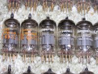
Amperex USA Made ("*" Factory Code) 6922 Vacuum Tubes Gold Pin ("7L" Type Code) AMPLITREX Tested

PLEASE READ THIS LISTING IN ITS ENTIRETY, INCLUDING ALL TERMS AND CONDITIONS!

By purchasing from this listing, you acknowledge that you have read and understood this entire listing, including all my terms and conditions, and agree to accept and abide by those terms and conditions.

I am cleaning out some stuff, and I have this group of 101 Amperex USA made 6922 vacuum tubes.

Price is $3000 for the entire group of 101 tubes (excluding shipping).

I have the descriptions, date/factory codes, test results, notes and "single tube" prices in an Excel spreadsheet, which is too large to post in this ad. The spreadhseet can be downloaded here:

Dropbox - 6922 Tube List Ad.xlsx

"Single" tube prices are listed in the spreadsheet. Discounts may be available for multiple tube purchases (depending on the number of tubes). The price is based on a number of factors including overall Gm, triode balance and my very subjective microphonics test (more detail below). Microphonics is weighted higher than the other factors. For example, if you see a tube that has a good Gm and is relatively triode balanced but the price is lower, then that means it is my uneducated OPINION that the tube may potentially be more sensitive for microphonics.

A quick note about microphonics - all tubes are little microphones and are microphonic to some degree. Whether an individual tube is unacceptably microphonic or otherwise noisy in a certain piece of equipment is anyone’s guess (and generally subjective). The Amplitrex does have a headphone jack for checking noise/microphonics, and I have used this to check these tubes while testing. Unless noted in the spreadsheet, these tubes do not (in my sole and uneducated opinion) appear to be abnormally microphonic (and most appear to be very low on the microphonics scale). With almost all tubes, you can hear the tap of a pencil to different levels. There were some with a little more tap noise than others, but none sounded like church bells in a canyon. My opinion is NOT, however, an indication of how these tubes will sound or perform in your equipment, and there is absolutely no guarantee against microphonics or noise under any circumstances.

I will consider taking some trade (see the bottom of this listing for further details).

As tubes are sold, I will update the spreadsheet and this listing.

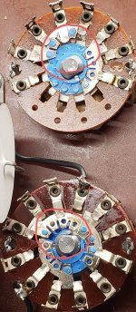
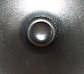
Internal construction of all these tubes appears to be the same, with a large halo getter element. Some are Amperex branded and other are Hewlett Packard branded, with various different types of print.

All but 4 have clear etched "*" factory code and "7L" type code. The 4 where I cannot read the code are clearly part of this same grouping. Dates appear to range from the early 1960s to late 1970s, but most appear to be mid 1960s through mid 1970s.

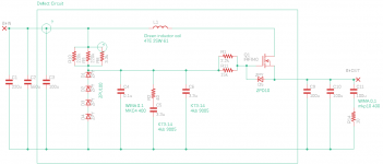
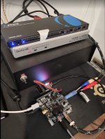
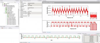
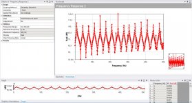
I tested all the tubes on an Amplitrex AT-1000 connected to a regulated power supply. The tubes were tested in fixed bias mode, and the test cycle was run at least twice for each tube (better warmup time and stabilization).

Test conditions are Vp = 90V and grid = -1.2V. Under these conditions, the spec for transconductance (Gm) on the AT-1000 is 12.5 mA/V (12500 micromhos).

Please note the date/factory codes are sometimes difficult to see, so they are as best as I can read them.

For the purposes of this sale, all of these tubes should be considered USED.

I can provide additional information or photos on request.

GENERAL TERMS AND CONDITIONS

Please note that these tubes are being sold "AS IS, WHERE IS". There are no returns or refunds under any circumstances UNLESS I have grossly misdescribed what I am selling.

Notwithstanding, I am an honest seller (please check my feedback on EBay, ID=baileyler), and if there are truly any issues with these tubes that were not described (other than microphonics/noise) and can be verified, then I will work with any buyer on a reasonable solution.

For further clarification, I ONLY describe what I know about the tubes, and what I have tested for. While my tube testers tend to be reliable, YOUR TUBE TESTER MAY GIVE A DIFFERENT RESULT THAN MINE, so please take that into account. In the event of a tube tester conflict, MY TUBE TESTER CONTROLS.

AS SUCH, PLEASE NOTE THAT I CANNOT GUARANTEE (OR EVEN REMOTELY PREDICT) HOW THESE TUBES WILL SOUND OR PERFORM IN YOUR EQUIPMENT. ANY TEST RESULTS ARE ONLY PROVIDED AS AN INDICATION OF TUBE PERFORMANCE IN A VERY LIMITED (AND IDEAL) ENVIRONMENT. EXCEPT AS EXPRESSLY INDICATED IN THIS LISTING, I DISCLAIM ANY AND ALL REPRESENTATIONS, WARRANTIES AND LIABILITY WITH RESPECT TO THESE TUBES, OR RESPONSIBILITY FOR YOUR USE OF THEM.

Payment can be via money order/cashier's check/personal check, but all must clear my bank first. Cash is OK for a local transaction.

I also accept Paypal for convenience. IF YOU PAY VIA PAYPAL, HOWEVER, A CONDITION OF YOUR PAYMENT IS THAT YOU EXPRESSLY WAIVE THE RIGHT TO FILE A PAYPAL CLAIM OR CHARGE BACK (but do retain the right to sue me in court should you so desire). While no fee Paypal is preferred, I will cover any Paypal fees.

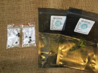
Each tube will be individually wrapped in bubble wrap and numbered according to the Excel spreadsheet. As a result, please give me a couple of days to pack properly and ship.

Shipping will be via USPS Priority Mail unless otherwise requested.

Please request a shipping quote in advance.

I WILL NOT FALSIFY INFORMATION ON A CUSTOMS FORM.

Shipping terms are EXW US Post Office (INCOTERMS 2010). In accordance with these terms, I will deliver the lot into the possession of the US Post Office, and once in the possession of the US Post Office ALL RISK OF LOSS PASSES TO THE BUYER.

WHAT THIS MEANS IS THAT I EXPRESSLY DISCLAIM ANY AND ALL RESPONSIBILITY FOR DELIVERY (INCLUDING BUT NOT LIMITED TO DAMAGE OR LOSS) BY ANY POSTAL SYSTEM, AND BY PURCHASING YOU EXPRESSLY WAIVE THE RIGHT TO FILE A CLAIM (INCLUDING BUT NOT LIMITED TO BUYER PROTECTION CLAIMS WITH PAYPAL) FOR ANY SHIPPING RELATED ISSUE.

If, however, you have purchased insurance for the item, I will assist to the best of my ability in the processing of any legitimate insurance claim you desire to file.I accept Paypal, US Postal money orders and cash (for local pickup). While no fee Paypal is preferred, I will cover any Paypal fees.

I will consider some trade, but frankly I have no specific needs. Tubes of interest include 5992, L63 (GEC tubular brown base), 805, 5Y3GB (Euro), 7731, 45, KT90 (EI), 7189, ECC801s (Telefunken, Siemens), a single like new testing Telefunken E88CC (Ulm factory, 1960 date), a single like new testing Brimar CV1985 brown base (KB/FB,1950s) and various other things at the right value. I have too much equipment at the moment, but might be interested in an 845 or 211 based amp (and power tubes). A higher-level gaming computer or parts (CPU, GPU, MB, SSD, RAM, display, VR, etc.) or a recent-gen iPad/Mini/Air (or similar) may also be of interest.

In any event, it does not hurt to ask, as something my catch my interest, but please keep in mind that my asking price is a bulk/volume price, so do not expect to get full retail price for your items of trade.

Please check my feedback on Ebay (ID=baileyler) and buy with confidence.

Attachments

  • P1010487.JPG
    P1010487.JPG
    728.9 KB · Views: 379
  • P1010489.JPG
    P1010489.JPG
    705.4 KB · Views: 340

Delsol- inexpensive full range bookshelf.

Here's one I've been keeping under wraps, but it's time to share.

Use the Aura NS3-194-8E, on sale for $10.50 from Madisound.
http://www.madisound.com/cgi-bin/index.cgi?cart_id=1251650.9881&pid=1705
Ignore the fs, it does far better than the numbers indicate.
Especially in my box.

One half sheet of MDF (you might could squeeze it out of a quarter sheet, with no mistakes)
Some padding for the back wall ( felt or carpet pad)
2"dia PVC (you can play with the port size)
1/2"hardwood face, or use 1/2" MDF or birch ply if you have to, but it won't sound as good. Mine is maple.

I developed this for use with the t-amp, and have found it works very well with the higher powered amp6.
I present this as an experimental starting point, and welcome suggestions.

design goals were-
cheap,
simple,
audiophile sound,
no crossover, just a driver (mechanical mods only),
rock the party.

plans at -
http://www.flickr.com/photos/47642593@N00/295706737/

Just build 'em- I think you'll be glad you did.
Pekar

Attachments

  • delsolsm.jpg
    delsolsm.jpg
    41.3 KB · Views: 7,078

Adapting a power supply

I am adapting an existing balanced preamp chassis and power supply and need help. It is a 60v regulated supply with two 30v+30v transformers and two zener diode regulating chains. I want about 24v output. The schematic is below. The Zener are 9.1v each. First, can I use one of my existing transformers for both sections? Second, do I simply leave 3 active Zeners on each section, for 27v (+ and -)? Do I remove Zeners from the circuit by laying a wire across them or what.? Thanks

Attachments

  • 374CB823-3125-4F72-B233-8F06920FC175.jpeg
    374CB823-3125-4F72-B233-8F06920FC175.jpeg
    53.2 KB · Views: 123

Cap MX modules, PCB's and other high quality items.

Some fully built SMD Cap Multiplier modules, design by Mark Johnson, PCB layouts by Prasi. These little supplies are excellent and I'm using them in my Whammy and Marsh HPA. These are not adjustable regs, the dropout is only a couple of volts and the trimmer only adjusts by a volt or so to fine tune the rails.

details of the circuit and boards are here from post #613 - Juma's Easy-Peasy Capacitance Multiplier

These have been carefully built with matched SMD transistors, MELF 0204 resistors, nichicon/Panasonic caps. Complete with DF01 rectifiers they are stand alone dual supplies up to 35V

One pair of Low power SMD Cap MX modules are available. £35 a pair - see pics in post #9


-----------------

ONE MID POWER SUPPLY IS now AVAILABLE - fully loaded and operational with ultra premium parts. Please see pics in post #9 - LT4320 Mosfet bridge with 4 x UKW 4700uF CRC filter into Cap MX. Superb quiet supply with lower dropout. This was my golden reference perfectly built with selected Toshiba transistors - £55 plus shipping

Two mid power MX PCB's with SMD parts fitted, no other parts - £5 each
[/B]
-------------------

Prasi design, one pair LT4320 bridge CRC power supply PCB's with extra Cap MX boards. Superb quality boards by Prasi, the MX PCB's can go between the caps or at the output for CRC -> MX

£15 shipping £5

Attachments

  • IMG_2482.jpg
    IMG_2482.jpg
    123.9 KB · Views: 370
  • IMG_2485.jpg
    IMG_2485.jpg
    102.9 KB · Views: 357
  • IMG_2479.jpg
    IMG_2479.jpg
    104.1 KB · Views: 363
  • IMG_2480.jpg
    IMG_2480.jpg
    98 KB · Views: 362
  • IMG_2493.jpg
    IMG_2493.jpg
    126.3 KB · Views: 369
  • IMG_2490.jpg
    IMG_2490.jpg
    125 KB · Views: 138
  • IMG_2494.jpg
    IMG_2494.jpg
    89.6 KB · Views: 124
  • IMG_2487.jpg
    IMG_2487.jpg
    165.4 KB · Views: 156

Best replacment for NE5532 in Phono preamp

As above, I have searched this forum without reaching a conclusion.

The design in question is Rod Elliot Phono (RIAA) Preamp. A simple job, that actually does the job quite well. I use this to transfer LP's to my PC for further processing and burning on CDR.

However, there is a bit of nasty shrillness in the upper middle ranges. This becomes quite evident in loud female vocal material such as Connie Francis etc.

Would changing the opamp make any difference? I have tried OPA2134 with slightly better results in the lower ranges. I have used fairly standard components in my construction and a well laid out homemade PCB. The pre-amp is stuffed into a metal box that sits inside the TT with external power supplies (even for the TT motor). Hum is zero with just a wee bit of noise.
Thanks in advance.

TPA3116D2 and NE5532 Pre amp

Hi everyone!!

I am trying to use the TPA3116d2 and NE5532 Preamp in the car.

However I just found that the NE5532 is running on 12V AC and not DC so is there any way to use this in the car as in car we have only DC Voltage.

Also I have connected a small MH 32 Bluetooth to the audio input on TPA and when I turn on the amp in the car it gives lot of noise.

Is there any way to eliminate that weird noise from the TPA on Bluetooth in the car.

TIA&#55357;&#56911;&#55357;&#56911;

Attachments

  • IMG_20210208_192112.jpg
    IMG_20210208_192112.jpg
    367.5 KB · Views: 311
  • IMG_20210208_192128.jpg
    IMG_20210208_192128.jpg
    518 KB · Views: 297
  • 20210208_124119.jpg
    20210208_124119.jpg
    995.1 KB · Views: 315
  • 20210208_124138.jpg
    20210208_124138.jpg
    654.7 KB · Views: 290
  • 20210208_124149.jpg
    20210208_124149.jpg
    771.1 KB · Views: 321

NAD C325BEE - burnt components on AMP-SMD-L BOARD

Hi,

my NAD C325BEE has some burnt components on the AMP-SMD-L BOARD (left channel). See the pics.

The amp was having some problems in the previous 6-12 months like not going into "ON" mode. The LED was going from amber to red but after a few retries the problem went away.

Yesterday, after a burning smell coming out of it, the LED remained amber all the time so I decided to open it and see what's going on.

The thing is that I do not know why this has happened and what to do to fix it. Should I change the whole board or replace parts. The second is a bit difficult as these are smd's and I don't have the proper equipment. I wonder if I can use regular components.

Changing the whole board makes more sense but what if the root of the problem is somewhere else. And I do not know how easy is to find these boards online.

Any help would be appreciated.

(service manual: http://www.hifiengine.com/manual_library/nad/c325bee.shtml)

Attachments

  • 1.jpg
    1.jpg
    173.3 KB · Views: 904
  • 2.jpg
    2.jpg
    132.9 KB · Views: 490
  • 3.jpg
    3.jpg
    125 KB · Views: 466
  • 4.jpg
    4.jpg
    130.4 KB · Views: 607

2 way speaker with Deltalite ll 2510 & Ciare 1.38TW

I had an idea to make a pair of 2 way speaker some two years ago and I suddenly came across a tread talking about KT88SE amp by Scott 17. He did mention that he had designed a 2 way speaker with the above drivers. Oh...I thought it was perfect fit to my desire since I have the Deltalite II 2510 in hand and I can easily switch them around. Scott 17 was so friendly and generous enough to provide all his design and details for making this speakers. Hey, it's easy enough for me since I almost have all the parts in hand, and I only have to rewind some coil to fit. But I had a personal reason to start this project late until couple months ago. I talked to Scott again and asked if there was any change on his design, I then started ordering the Ciare 1.38TW and some resistors.
Long story short, I have all the ply cut and assembled right after. See how it goes.....

Attachments

  • 2510.PNG
    2510.PNG
    73.2 KB · Views: 693
  • 2510 co.PNG
    2510 co.PNG
    49.5 KB · Views: 692
  • 20150919_113326.jpg
    20150919_113326.jpg
    623.5 KB · Views: 683

Hybrid SS PA: How to drive a push-pull VAS with a single input signal from an op-amp

Hi, I am trying to create a circuit to drive a push-pull VAS with a non-differential signal from an op amp. The output of the AO has as maximum values ​​+-vin (much lower than the supply voltage of the VAS) so I thought of adding two DC components to this signal:

VDC1 = Vcc-k * vbe (Qvas) and VDC2 = Vee - k * vbe (Qvas)

Where k is greater than 1 to implement later a simple current source and active load on the VAS with an emitter resistor. Also Vdc1 = -Vdc2.

My idea was to use a circuit like the one in figure 1, but apparently I am wrong in some important concept because it does not work at all in the way I want, additionally looking around I´ve found some similar circuits but those use two diodes in series from the collector of Q1 to the collector of Q2 (figure 2) and this confuses me: doesnt this limit the maximum excursion in each collector to vin + -2 * Vd at the same time they increase the power dissipated in Q3 and Q4 in the absence of input signal? (the power supply of figure 2 is + -90Vdc).

I will appreciate any help or clue you can give me in this regard, I am not interested in the exact values ​​I want to understand how to calculate them, and if there are any important considerations to make.

PD: sorry for my caveman-level english 🙁

Attachments

  • circuits.png
    circuits.png
    27.6 KB · Views: 227

recycle smps

i have a big problem. , i state that i don't have much knowledge of smps, but i like to build audio amplifiers. time goes I bought from China grande smps llc pusch pull full bridge 3000watt..some time ago a big lightning bolt destroyed many products of the house, and this smps too .... unfortunately I can't repair it because many pieces have the name deleted replacing them with uncertain pieces scares me .. lately i came across these smps power supply circuit with ir21531. i saw that they are very simple to make and very efficient. i would like to try to build one of these smps to power a powerful subwoofer. from a careful study I was able to read the power MOSFETs they are stw45nm50 and I also believe the l6599d driver. but despite the replacement it does not work properly, it emits a loud buzz and does not hold the load ..... so here is my question, i want to replace all control and edit smps, but i need some help ... meanwhile l The amplifier that I have to power works with double 70v, it generates an audio power of 1000watt RMS on a load of 8hom. the power supply fuses are 6ampere per branch, so I think 1kw of smps is enough. my idea is to recover all the components of the old smps and rebuild it using this ir21531 or higher model ir2155 as driver and a pair of stw45nm50 to push the etd49 transformer. the primary MOSFETs are all tested and working, the transformer is good, the secondary is completely intact .. do you think ir2155 can drive stw45nm50? can you recover this smps?
Projects by fanatics, for fanatics
Get answers and advice for everyone wanting to learn the art of audio.
Join the Community
507,787
Members
7,888,508
Messages

Filter

Forum Statistics

Threads
406,242
Messages
7,888,508
Members
507,787
Latest member
AlexMack