What is GENTLON?
It is an after-the-fuse power entry control board that gently turns on the power to an amp (or other devices).
Is Gentlon not just another soft-starter?
Yes, it is, if one doesn’t care a short list of a few little things more than what a usual soft-starter does, and the way that it does them. Otherwise, the list goes,
1. Power-Good driven: Gentlon soft-starts the power, but does not turn power full on until a subsequent Power-Good condition is established. If Power-Good fails to establish within 5 seconds after soft-start, the circuit gives up and returns to power off (standby) mode.
2. Has onboard Power-Good monitor that watches up to 4 DC rail voltages, 2 positive and 2 negative, detects rail droop/collapse and defeats Power-Good accordingly. The threshold voltages for Power-Good and rail collapse are user-defined (by resistor values).
3. Two wire headers offer off-board speaker relay drive, at 12V/100mA capacity each, also sustained by Power-Good,
4. A wire header offers off-board power relay drive if choose to have the power relays and the NTC thermistors installed elsewhere in the chassis.
5. Accepts speaker kill override.
6. Accepts power kill override.
7. Has on-board bulk capacitor bleeder, fully discharges rail capacitors in seconds at power off. (Can be defeated with a jumper)
8. Allows installing up to three 1-in diameter NTC thermistors, offering generous Joule handling capacity for even "ridiculously" large bulk capacitance on the power rails.
9. Has a NTC cool-off timer that blocks repeated, frequent power-on attempts. It gives the NTC thermistors chance to cool down and come back to normal resistance to help ensure adequate inrush limiting performance at each power-on event.
10. Rev.3 PCB offers relay-switched Neutral connection, in addition to the usual switched Live wire. (Rev.2 PCB does not switch Neutral, but it has a 30A relay.)
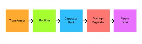
How does it operate?
A simplified flowchart:

Note about the “Plateau”: A time delay placed after the soft-start before probing the PG status. If one wants to probe the PG and shunt the NTC sooner or later this is where to make the tweak. But it is up to 5 seconds, or the circuit goes back to Standby state.
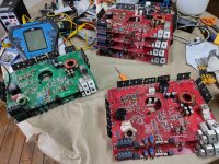
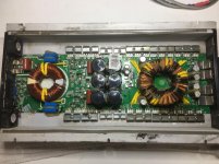
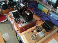
Has it been built and tested?
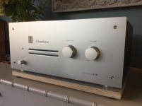
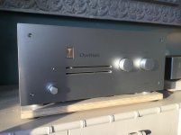
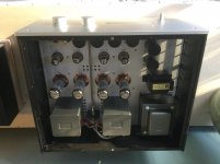
Built a few Rev.2 Gentlon, all operate properly. I have one of them in a dual mono power amp (Meistersinger amp, my own design and build) with two 600VA toroidal transformers, followed by 120,000uF total capacitance on +/-65Vdc rails, in service for 5 years now. Have never built the Rev.3 Gentlon, but the only difference from Rev.2 is the added option of the switched Neutral, and a 16A relay instead of a 30A relay.
 There are loads of SMD parts, can someone new to SMD build it?
Unlike most other SMD PCB designs seen in our forums that simply take standard IPC7351 compliant footprints, I make all SMD footprints specifically suited to DIY hand soldering/reworking. All land patterns in my PCB designs have ample pad exposure beyond the component body for easy iron tip access. The smallest size SMD part used is the large-ish and easy 0805, making the Gentlon a good SMD beginner's project. A usual temperature controlled soldering iron and a pair of fine tipped tweezers would be adequate for assembling this PCB (what I solder mine with). For advanced level builders in terms of SMD experience and equipment, this PCB is also suited to reflow assembly process.
 What's being shared?
Schematic diagram
View attachment GENTLON_2.pdf
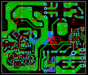
PCB fabrication data package (can be sent straight to a fab house to order PCBs, as well as the paste stencil if desired)
View attachment Gentlon_2_Gerber.zip
BOM
View attachment BOM_Gentlon_2_Raw.txt
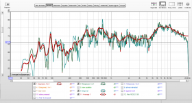
An LtSpice power rail monitor schematic for simulating/altering resistor values to suit desired Power-Good voltages and the hysteresis, or the protection threshold. The un-altered circuit validates Power-Good at about 56.5V, and defeats it at about 55.5V.
View attachment GENTLON_2.asc
2. Assembly Options
Some functionality of the design can be opted out.
Don't want the Bleeders? Delete all components in the "Cap Bleeder" box in the schematic, with the exception of the four 10-ohm resistors and J11.
The amp has only one pair of DC power rails to monitor? Connect the DC power rails to J11, delete J10, D10, and D11
Use no more than one NTC? Use a proper resistance value and current rating NTC, delete the other two from the BOM and short their soldering pads.
Power rail on different voltages? Simulate for the desired voltages in the LtSpice schematic and change the resistors in the BOM.
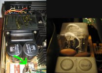
What does it look like when in action?
Gentlon_in_Action
Sorry, ran out of hands...
😀


 Thread split from here -


