autotransformer inrush current?

I'm familiar with inrush current problems, and inrush limiting, for power transformers. But what about an auto-transformer/autoformer? Do these also have inrush current like a "regular" transformer? I can't quite figure it out. The reason I ask is that I am looking to power some 220V European gear from my US 120V mains. It's a class-D power amp, so peak current draw in use might be high, and so I would need a large auto-transformer and so am concerned that commercial "voltage converters" may need soft start capability. The amp already has it, I am thinking about no-load conditions when I switch on the auto-transformer prior to any other equipment.

Can someone shed some light on this for me, please? Thanks!

CMF55/RN55 Resistors real power rating

I'm about to order the parts for the Honey Badger class AB amplifier and I want to use vishay dale resistors. According to the datasheets of CMF55/RN55, the two variants are physically identical, except of the military standard ratings of the RN55. Looking at the datasheet of CMF55, one can see that it handles .5w for an ambient temperature of 70C. Does that mean that I can use CMF55/RN55 resistors in circuits that require .5w resistors? Also, if you take a look at the RN55 datasheet, a power dissipation of .125w is stated for Tamb=70C. I'm a bit confused and I don't want to order a bunch of resistors and watch them burn, so could you please help?😕

Arcam Alpha Integrated Amp toroidal

I have an Arcam Alpha mk1 with seemingly a faulty transformer. Two of the rectifier diodes D203 & D204 are shorting either way, if the transformer secondary wires are a removed from the pcb then they are as a diode should be. D203 & D204 are ok with the transformer connected. I have a new replacement transformer but I get the same shorts with that as well! Am I wiring it incorrectly? The original arcam one has orange blue orange but I'm not sure how the new Noratel one would match this?

chrome-extension://oemmndcbldboiebfnladdacbdfmadadm/http://www.farnell.com/datasheets/90564.pdf

Econowaves - Fill in the Blank

I recently built a rather large three way stack comprised of (2x) tall VBSS 18" cabinets, and tops made of an 8" midrange driver and a DE250 on an ME20 horn with a very basic passive crossover. I'm very dissatisfied with the midrange - for a while I blamed the crossover, but lately I'm wondering if the driver selection isn't also a problem (8" being too small for this application). I took on more than I can handle - so I'm taking a mulligan and looking for a more fully-baked design.

This led me to exploring the Econowave concept, which seems to get rave reviews and fits what I'm shooting for - high sound quality and high efficiency. Based on what I read I can repurpose the DE250's (great), and I'm leaning towards a 12" version as these tops will have subs to go with them. Here's my main question:

In 2021, what horn's are available for an Econowave build? I see the Dayton clone of the (JBL?) version people used in the past is sold out, and in any case that needs an adapter for my DE250's which likely means adjusting the tested-and-proven XO's out there. The larger QSC waveguide doesn't appear available anymore. What other options do I have?

Dayton Audio L-pads

I needed some L-pads to balance the mids to the bass panels so I ordered some from Parts Express. I didn't realize until they arrived that I had ordered the 16 ohm version.

If you can use these I will send them to you for the cost of shipping.

Dayton Audio L-pad, 50W mono, 3/8th inch shaft, 16 ohm

PN 260-254

$10.98 each from Parts Express. Free + shipping to good home.

Infinite impedance amplifier idea J Broskie

Hi!
John Broskie had the idea of such amp for HP driving to make upper amp (tube) seeing infinite impedance of the load: Infinite-Impedance Amplifiers and Crossovers
I tried to use it for speaker driving, sim results attached.
RS is for exact impedance matching, the formula (0.125/0.111-1)*3=0.375 is in linked blog, for 3 Ohm (my Magnepan 1.5) Rs=0,375
However when Rs=4 Ohm THD is much lower (probably because both amps are working and putting the current to the load), you can see it in atachments.
I think achieving so low THD with a few parts is interesting, what do you think?
Not bench tested, but there should be no oscilations due to not too little gain of chip amps.

Attachments

  • Sch inf amp JBroskie.png
    Sch inf amp JBroskie.png
    65.8 KB · Views: 316
  • sinewave20kHz.png
    sinewave20kHz.png
    31.1 KB · Views: 320
  • fourier Rs4 Ohm.png
    fourier Rs4 Ohm.png
    39.1 KB · Views: 301
  • Fourier Rs 0.375 Ohm.png
    Fourier Rs 0.375 Ohm.png
    34.7 KB · Views: 303
  • lm1875 iinfinite imp amp TCJ 06-02-2021.asc
    lm1875 iinfinite imp amp TCJ 06-02-2021.asc
    2.2 KB · Views: 50

William Chater's "Bias control for power amplifiers," Revisited

I was reading through old diyaudio threads when I came across a name I remembered, and a circuit invention I played with about thirty years ago.

In 1988, Mr. William Chater published "A 40W All-MOSFET Power Amp" in Audio Amateur. I was quite taken with it at the time. Not the all-MOSFET design, but the 4-opamp servo he was using to set the bias current of his output transistors. I'm attaching a picture from his patent, which is for the servo, not the amp.
http://patft.uspto.gov/netacgi/nph-...50&s1=5055797.PN.&OS=PN/5055797&RS=PN/5055797

I adapted that bias servo to a triple-EF design I was working on at the time. It's really a very cool idea. The minimum of the voltage across R44 and R45 is proportional to the idle current, regardless of signal level. Let's sense the voltage across those resistors, and detect and hold the minima with a large enough time constant to control the DC bias.

  • A1 senses the difference across R44 & R45.
  • A2 and A3 sample the minimum of that difference. A2 quickly samples the minimum, and R47 lets it decay (very) slowly.
  • A4 is an integrator, of course. The bias control signal must be well-below audio frequencies. A4 sets the current of TR5, which sets the current of Q6 and Q7. Q6 and Q7 set the bias of Q11 and Q12 with currents into R41 and R42.

Ultimately, I found the bias servo to be impractical. The reason is that R50 - R53 must be very closely matched to have enough common-mode rejection for this to work. I built it with 1% resistors for R50 - R53, and initially it seemed to work. However, when I hooked it to a loudspeaker, it fell apart. With a resistor load, zero-crossing of the current and voltage coincide, so not much CMR is needed. With a reactive load, A1 is trying to sense a very tiny difference voltage on top of a very large common-mode signal. Bias jumped all over the place, and I was afraid the amplifier was going to burn up.

I replaced R50-R53 with 0.1% resistors, and that helped a lot, but bias was still kind of jumpy with certain music and certain speakers.

I long ago had an idea for how to fix Mr. Chater's bias servo, but I'm just now getting around to trying it. It's a tricky circuit. Special attention has to be paid to the initial conditions of C26 and C20, and the relative time constants of the min detector and the integrator.

Attachments

  • Chater_patent_5055797.png
    Chater_patent_5055797.png
    177.8 KB · Views: 768

Altec 604-8G bulid

Hello all good people out here. The other day I found a couple of 604-8Gs that I purchased from a local studio 30 years ago. I will try to make new boxes for this in the upcoming month or so.
1. question - They need reconing of the woofers. A friend of mine said the I could use the cone meant for the 515 bass. Is this a smart thing to do? And do anyone know where to get this parts?
2. I´m looking for a narrower box than 620 as it will be easier to place in a living room. Is there any other possibilities here?
3. What kind of amplifier would be a good choice here. VALVES? - I do have a Bryston 4B and also a 3B.

Thank you for reading 🙂
N

Conrad Johnson PV-10 squeal!

Hello,

I am having a small but annoying problem. I have a Conrad Johnson PV-10A that has developed a high pitched squeal that is independent of volume and intermittent. It will usually go away for a while if I cycle the power on the preamp.

The problem has persisted through several pairs of tubes. I finally paid some serious(ish) cash for some very carefully screened, ultra quiet, new production 12AU7's. Squeal is still there. Changed amps. Still there.

Any thoughts?

Thanks for your help!

Cheers,
John

hey everyone

My name is Henry, and I was surprised to find such a community 🙂

I've been interested in all things audio since an early age, in particular interested in radio and hifi. I have fond memories of doing summer jobs as a schoolkid to be able to afford what I considered to be a "proper" hifi - ie separates. I bought a second-hand NAD amplifier, a pair of Wharfedale speakers and a Technics CD player and Technics cassette deck (remember them?!) - That was all pretty unusual back in the day because at the time, the market was flooded with low-end trash products by Amstrad and all the rest.

:wave2:

Custom All in One Mobile Audiophile System - RP4 / DAC / DSP / TPA3255 / PS

Looking to get some ideas on some premium components for a custom build. I'm a trainer for a trucking company and I take students out on the road for 6 weeks all over the US in a sleeper semi-truck ( Kenworth T680 with 1400 watt inverter )

From what I’m seeing the TPA3255 can make for a fantastic platform to build an audiophile system, if done right. Currently I’m using the existing factory 4 channel radio with a Samsung S6 table for Navigation and as the music player with USB out to a USB hub / Topping D10s than to the aux-in on the radio.

I’m wanting to design an all in one case with a 5 or 6 channel system to drive the front (2) 4X6 door speakers the (2) 5 1/4 rear speakers, and add a small subwoofer under the front seat or both front seats. There are a few places I can install the case in the semi-truck, so I have some flexibility there. I’m thinking under a cabinet in the rear of truck would be a good location.

I know speaker sizes suck ....... it is what it is......Enough of that….. Here is a list of the items

Case
1 or 2 cases, would prefer all in one case.
If need be add copper shielding of components.

Rasberry Pi 4
As Audiophile Player
Player Controlled by Samsung S6 Tablet
Why Raspberry Pi? Android USB audio driver resolution limitations.

USB DAC
External Power supply
Interchangeable Op-Amp would be a nice addition

DSP Board
Up to 6 channels

TPA3255 Boards
What (3) 2 channel Boards?
Dr Mordor Boards?

Power Supplies
Linear or Switched?

Extras
Maybe a Custom Head unit - single din slot in the dash with custom milled/CNC aluminum plate with Arduino board to control volume/Play/Next Previous track/Pause and music spectrum display.

Controls
Ability to Fade or turn off the rear speakers when someone is driving and the other is sleeping in the rear sleeper of truck.

The goal here is the ultimate custom sound system that can be modified, changed and updated in the future.

I also am considering paying someone to fabricate and assemble some, if not the entire system, as I don't have much time off from work.

Powerbass 3200W faulty - someone able to assist please?

Hi DIY-ers.

Firstly, thanks to those responsible for hosting such an inspirational and informative site. 2nd, I have never repaired or built an audio amp successfully, and lack the confidence to do so. I hope this will be my first.


Str8 to it ->

I cant say when or how the fault happened, just that it started to put out a very crackly distortion sound on 3 of the 4 channels. Strange that 1 ch Is working 95%.


There was a 33nf ceramic cap that showed zero continuity when tested. I replaced it with the exact same value. And just for peace of mind I reached the 3300uf 50v caps with 2 x 4700uf 50v caps. Upon testing after putting it back together, all channels were clear and worked, and then went back to the same way it sounded before.


If anyone needs specific pics please dont hesitate to ask. Any idea on where to start investigating?
Thanks in advance...

Attachments

  • images (5).jpeg
    images (5).jpeg
    19.7 KB · Views: 121
  • 20210220_153950.jpg
    20210220_153950.jpg
    508.3 KB · Views: 174
  • 20210220_153901.jpg
    20210220_153901.jpg
    962.1 KB · Views: 132
  • 20210220_153838.jpg
    20210220_153838.jpg
    435.3 KB · Views: 124
  • 20210220_153915.jpg
    20210220_153915.jpg
    503.5 KB · Views: 141
  • 20210220_152703.jpg
    20210220_152703.jpg
    529.2 KB · Views: 121
  • 20210220_152645.jpg
    20210220_152645.jpg
    536.3 KB · Views: 98

What causes inline pictures to show up differently from time to time?

1st picture from the left
So when people attach pictures inline it often displays some pictures differently despite all pictures being of same size.
See the attached picture and one can see the smaller pictures has a width="600" addition in its HTML code while the upper larger pictures doesn't.

2nd picture
Reloading the web page and they are all expanded fully (which is wrong behavior, as all pictures should be downsized to 600px width before clicking on picture and panning in).

3rd picture
Expanding the browser window to cover the whole computer screen, in my case 1920px wide and reloading, all the pictures are now downsized as should be down to 600px width, but I never use browser in fully expanded mode so I don't see it as a solution.

Just one example found in the following post out of thousands and has been so for a few years.
Low distortion current driven Class-B output stage

Then there's the other variant where a small thumbnail like picture is attached inline, clicking on those send the browser to a new page and so the current post on DiyA one is currently reading vanishes, it's quite frustrating when interpreting a complex schematics while concurrently reading the post describing the circuit, I hope pictures without panning and dragging function will be completely abolished in the future.

But I guess it's all a "won't get fixed" case until the new forum SW upgrade, although it was promised at least some 2 years ago it would come "soon", I don't blame anyone for the slow transition, but maybe the maintainers of the forum are instilling themselves into a state where they stop fixing even some simple bugs because the new forum SW is always "just right around the corner"..., ok rant off for now. 🙂

Attachments

  • DiyA pic attachment 1.jpg
    DiyA pic attachment 1.jpg
    176.7 KB · Views: 98
  • DiyA pic attachment 2.jpg
    DiyA pic attachment 2.jpg
    175.9 KB · Views: 92
  • DiyA pic attachment 3.jpg
    DiyA pic attachment 3.jpg
    201.2 KB · Views: 98

Restoring a General Radio 107N variable inductor

I recently acquired a General Radio 107N variable inductor. The front panel was in good shape but the enclosure, made of solid walnut boards, had a lot of damage to the finish. My goal is to clean the front panel, clean and lubricate the main and vernier dials and restore the enclosure as period-correctly as possible.

Attachments

  • 9D46B0E9-BD86-4463-983E-DB13C755C481.jpg
    9D46B0E9-BD86-4463-983E-DB13C755C481.jpg
    582.3 KB · Views: 124
  • 973DFD3E-21B5-4276-80A4-98365CA2FF32.jpg
    973DFD3E-21B5-4276-80A4-98365CA2FF32.jpg
    924.7 KB · Views: 155
  • 7BB67D4B-7CA1-4741-93D3-CAD00285B292.jpg
    7BB67D4B-7CA1-4741-93D3-CAD00285B292.jpg
    947.9 KB · Views: 120
  • 5486B97E-E784-4B01-BFB3-BDD17184BBB2.jpg
    5486B97E-E784-4B01-BFB3-BDD17184BBB2.jpg
    887.9 KB · Views: 135
  • 4593AA7D-F9C3-4F36-AF54-11FC3825DE01.jpg
    4593AA7D-F9C3-4F36-AF54-11FC3825DE01.jpg
    985.6 KB · Views: 159

Mtx 7801 q405?

Good day gents,
I got a mtx7801 that came in, no audio, no high current.

Power supply drive components were replaced and amp now powers up with LED 401 lit.
I have rail voltages and +/-15v on the op amps, no R-R oscillation. I replaced both 5532 and opto couplers, I noticed Q405 missing, anyone knows which transistor goes here?

Attachments

  • 335FE25F-BB59-4DE8-873D-841859A07D2E.jpg
    335FE25F-BB59-4DE8-873D-841859A07D2E.jpg
    996.9 KB · Views: 138
  • 4A9470DA-8E3A-45AF-9E02-DE93BB588559.jpg
    4A9470DA-8E3A-45AF-9E02-DE93BB588559.jpg
    823.9 KB · Views: 113
  • 35B8994D-8207-4FDA-8B5A-03E161702CD4.jpg
    35B8994D-8207-4FDA-8B5A-03E161702CD4.jpg
    1.1 MB · Views: 103

Playthings of Past, Medina Ohio

SEPTEMBER 26, 2020 UPDATE:
Play Things Of Past is now under new ownership.


Play Things of Past, Medina Ohio (or Sunbury, Ohio)

I have dealt with this guy since the dawn of the internet, or before. Barns full of old radio parts; also books. He has passed away. New guy trying to deal with the orders.

New guy: Barry H Bennett, proprietor
Old guy: Gary B. Schneider

Obit: Obituary | Gary B Schneider | Waite & Son Funeral Homes
"Gary B. Schneider, 72, of Medina, passed away on Thursday, March 12, 2020. ....Gary served in the US Army and got promoted as a radar instructor during 1966 and 1968. He held an associate degree and started his own electronics business focusing on radios."

Converting from UL to Triode: Is this correct?

Hello all you smart helpful people. 🙂

I have an EL34 P-P tube amp that currently runs in UL mode.

I'd like to convert it to Triode mode to see if I like the sound.

I have done some research and come up with the plan on the diagram.

Is it correct?

Is there anything else I need to be aware of?

Also, where I have marked the red question marks, is this a feedback loop? Should I leave it alone?

An externally hosted image should be here but it was not working when we last tested it.

Are these leaky caps?

Have a NAD 7240pe with scratchy dropouts in the right channel preamp section. I’ve done the deoxit and cleaning to no avail. Thinking maybe it’s some caps, but never replaced them before. There are 3 caps in the preamp section that have some dried liquid around the base but I don’t know if this is a leak or just glue. Every other cap looks fine from the outside. Images attached are these leaky caps?

Thanks

Attachments

  • C83257EA-5616-4BA4-9387-DB3610A6AD85.jpg
    C83257EA-5616-4BA4-9387-DB3610A6AD85.jpg
    433.9 KB · Views: 144
  • 0738F4DF-820A-47CF-A367-CF7B80B3067E.jpeg
    0738F4DF-820A-47CF-A367-CF7B80B3067E.jpeg
    503.7 KB · Views: 138
  • 56C07E20-A344-4E1E-BEA3-55EA7BAEE2DB.jpeg
    56C07E20-A344-4E1E-BEA3-55EA7BAEE2DB.jpeg
    407.5 KB · Views: 142

Op amp Linear power supply

I have a question concerning the following. I am only a small time self taught hobbiest. I have a 741 op amp driving a TIP 102 NPN Darlington current pass transistor. I have two loads attached. One load draws .240 amps. The second load draws 1.150 amps. I can set the voltage output for the first load at 11.8 volts. When i switch the to the 1.150 amp load the voltage drops by almost .3 to .5 volts. My supply is 15 VDC. I use a 50 ohm resistor for the .240 Amp load and a 10 ohm resistor of for the 1.150 amp load. The transistors are heatsink mounted when testing. The heatsink temperature rises from about 23C to 77C with the higher amperage load. I also tried a PNP TIP 147 darlington and while it functions better suffers from the same larger than expected voltage drop changing from one load to the another. I have 2.4 to 3.2 volts on each darlington from collector to emitter so i think these are in saturation. I used the darligntons due to the op amp output current. The spec sheet says i only need about 300 microamps to get then current output. So, I tested a IRF9540 P channel mosfet with the same two loads and it holds within .04 volts regardless of load. Regulation from cold to hot is almost 99% accurate. Same temperature rise on the heatsink with the mosfet. I think I am operating the mosfet in saturation, but just barely.

Please help with any explanation as to why the darlington are losing, (not regulating) the voltage between current loads and any improvements I can make to allow the use of the darligntons. Regulation changes with an increase in temperature. How can I fix this too. I don't care whether I use NPN or PNP because they are inexpensive. Thanks.

First time with BSC320N20NS3 G on IRS2092

This is a small class D project targeting :

1. BTL mode, 2 x IRS2092, driven by OPA1632.
2. Using BSC320N20NS3 G 200Vds, 32mOhm, 22nC Qg
3. Output power still unknown, not going to put heatsink, trying to maximize the copper area for better dissipation.
4. Fault protection by sensing the PWM at low side gate driver.
5. Typical iraump Low/over voltage protection.
6. Reserved resistors & capacitors footprint on PCB for Post filtering feedback attempt, no idea if it works, but would like to give it a try.

7. ACDC 100khz to 150kHz LLC
8. 24V battery backup DCDC 100khz to 150kHz LLC.

Attachments

  • irs2092.JPG
    irs2092.JPG
    214.1 KB · Views: 255
  • LLC.JPG
    LLC.JPG
    152.3 KB · Views: 260

Resistors- Texas Component and Kiwame- Big SQ change

Hey, I've been a member and lurker here for years. I think this is my first post. I just recently had an interesting experience with my 211 based SE triode Wyetech amp and my results were so unexpected that I felt the need to post them. First off I am not a technician just a DIY hobbyist who is not afraid of a soldering iron and multimeters.

Just before Xmas my 211 amps L channel went out😡. Fortunately I had the schematic from Roger for the input and output side of the amp. I discovered my plate resistors(for the gain and driver stages) looked a little long in the tooth. Glazed and the board below had heat stains. Fortunately I had the same values on hand in Kiwame 5W carbon films. So I pulled the RCD and RCL wirewound resistors out and replace with the kiwame's. ( I know they won't last as long as the WW but I'll replace every 2 years or so). Needless to say I was surprised at the improvement is SQ. More transparent, better defined layering within the stage. Putting my ear close to the midrange/tweeter area I heard less noise, silence now. Almost like I made a major equipment upgrade not a plate resistor change.

This got me thinking and I started examining the schematic more closely and I found right at the RCA input a 1K ohm Halco H2 resistor connecting to the grid of my gain stage tube (6sn7). I also checked my schematic to my buffered preamp and found a PRP 9372 100 ohm resistor right at the output. I had read for years that bulk metal foil resistors were the closest thing to no resistor at all. So based on my plate resistor swap above I decided to get me 4 Texas components TX2575 bulk foil resistors to replace these already well regarded resistors (Halco, PRP). I reached out to Texas Components and Nelson Bustos replied back to me the same day and set me up with 2- 1K and 2- 100 ohm TX2575 resistors. They arrived in a few days and I soldered the 1K ones into my tube amp at the RCA input to grid of my gain stage tube (6sn7). I spent the next 3 listening sessions focusing on this change. I spend about 1000 hours per year listening to my main system, I know it well. The change made by the TX2575 replacing the Halco H2 had me grinning from ear to ear. It magnified the changes made by the Kiwame resistors. Much more transparency, more layering and separation within the sound stage, leading edges much better defined making dynamic contrasts even more pronounced. Another level of blackness (quiet), music was so involving I couldn't turn it off and I listened past 3 AM each night. I only reluctantly turned it off because I had to be awake the next day. My system that I know so well, had reached new incredible levels I thought impossible. The stage was organic and real.

After the 3 sessions I swapped the PRP resistor in my preamp to the TX 2575. This is right before my RCA output. Although not as dramatic change as the amp swap. what I heard was further enhanced. My stage got both wider (beyond the speakers on most recordings) and deeper. Layering seemed more obvious and the little percussion that many times is hidden in most playbacks was now more evident. I have now gone almost 2 weeks since the TX2575 swap. I just cannot get over the improvement it has made to my system. I rarely turn my stereo off before 3 am now. Music is so involving so real I just want to listen more. What started as a bad moment (L channel went out) has turned into a blessing. Thank you Texas Components and Kiwame. Sorry for the long post, I just had to share.
  • Like
Reactions: Milen Ivanov

Seismic Turntable Platform - Stops a Train

My seismic turntable platform:
In my early years of interest in high fidelity, my ‘listening room’ was on the second floor of a house built in 1916, which was 2 short blocks from a major railroad line. That should give you a hint of where this is going. As I moved up the ladder from VM changers with ceramic cartridges to a Dual 1019 and then a Thorens TD-125 that could handle <1 gram VTF magnetics, the audible effects of a passing freight train became, shall we say, intolerable. As my playback equipment got better, the vibration effects went from a very noticeable warble to groove jumping (watch out for flying tonearms). My first attempt at isolation was to perch the equipment cabinet, which was made of ½ inch walnut plywood and quite heavy, on 4 rubber blocks. This helped, but was still inadequate.


The severe movement of the turntables horizontally from the trains and the vertical sensitivity to footfalls on the second story wood floor was beyond the design limits of either the 1019’s or the TD-125’s spring suspension. Logically, the solution called for an external suspension mechanism, or ‘seismic platform’, that has these basic properties:


1. A natural resonance frequency that is much lower than the natural resonance frequency of the turntable’s own spring suspension. The intent here is that the seismic platform isolate the large magnitude horizontal and vertical floor movements, and leave the turntable’s own suspension deal with the higher frequency vibrations that it was designed for. The seismic platform should deal with and mitigate all the floor-born lateral and vertical shaking, including footfalls.


2. Any residual motion that does get passed on to the turntable must be at or below the natural resonance frequency of the seismic platform, and must be substantially planar, that is, not inflict any tilting moments on the plane that the platter and armboard are in. The intent here is that the operation of the seismic platform during a disturbance not cause the platter and armboard to ‘tilt’ under the tonearm, which could cause the VTF to vary during the disturbance.


3) Ideally, the horizontal and vertical natural resonance frequencies of the seismic platform should be independently adjustable or tunable, through selection of materials and dimensions of key components.


One thought was hanging the turntable base from a long spring, suspended from the ceiling. This would certainly satisfy Properties 1 and 2, but trying to keep the turntable from swinging and yawing after cueing a record appeared to be an inescapable problem. A technique currently popular is mounting the TT to the wall. This might have helped with mitigating footfalls, but wouldn’t help when the whole house is shaking sideways! Other brute force approaches using 200+ pound slabs of granite or concrete would be too difficult to navigate through doors and up stairways. Plus, the mass would still have to be suspended or floated in some manner that satisfies Property 2.


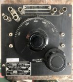
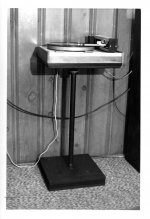
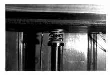
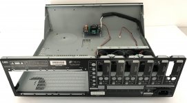
I came up with the seismic platform solution around 1972. My several moves since then eliminated the need for a seismic platform, so I disassembled it and put it in storage. I found the key parts the other day in the garage, with some rust and solidified grease, and decided to start a new thread in case this method fills the bill for someone else in a similar boat, or it might spawn some other useful ideas. The easiest way to understand the concept of how this seismic platform works is to imagine the turntable attached to the top of a MacPherson strut such as used in a typical front end automotive suspension. The piston moving up and down absorbs footfalls and vertical ‘trauma’. The spring rate is chosen so that, when combined with the total mass of the complete turntable assembly, the natural resonance frequency of the system is on the order of 1-2 Hz. Think of a car with worn out shocks going down the freeway, slowly floating up and down after it goes over dips in the road. To take care of horizontal ‘trauma’, the entire strut assembly is mounted on a spring base so that the turntable perched at the top can rock back and forth, at a natural frequency of no more than about 1 Hz. Note that although this rocking would seem to violate constraints outlined in Property 2, a horizontal movement of, say, ¼ inch on a 30” high strut would result in a planar tilt of only 0.5 degrees, and would occur at no greater than 1 Hz, which is easily followed by the tonearm. In practice, the actual horizontal movement was much less. How effective is the seismic platform? Before, passing trains made records unplayable (groove skipping in extreme cases). After, passing trains had no noticeable effect, even with tracking an ADC XLM at 0.6g VTF. In fact, I could do a skip jump in front of the seismic stand with hardly any noticeable effect. The effectiveness of the isolation was stunning. I found a couple of original photos of the platform, and I took some more of the disassembled parts to help you visualize how I put it together.


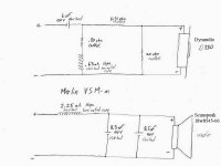
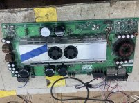
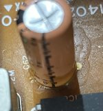
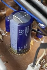
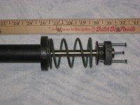
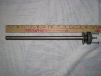
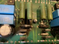
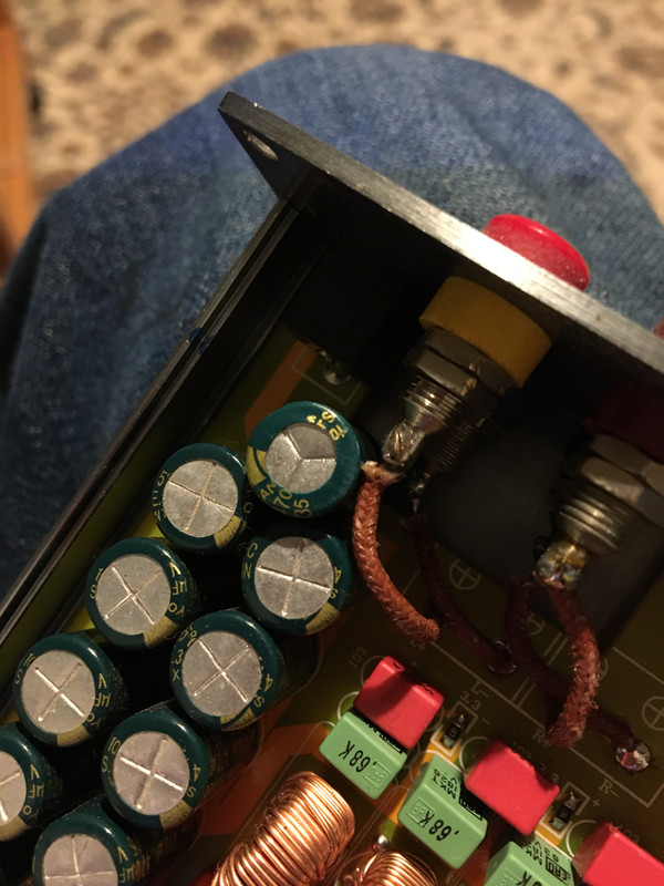
The key element in keeping the platform motion ‘substantially’ planar is the attached die ejector pin whose vertical motion is constrained by a set of linear ball bushings set in a 1” galvanized steel water pipe support. The platform in my case was a piece of ¾” particle board that I made into an integral part of the TD-125 base. The trick in keeping the natural vertical resonance frequency of the platform and turntable low is finding a coil spring with a soft enough spring rate (F = -kx) to work with the mass of the complete TD-125 ‘table, including wood base and arm. In this case I found that a hydraulic servo piston release spring out of a 1966 Chrysler automatic transmission turned out to be perfect for the job (don’t ask). You will have to be inventive to come up with the right spring for your platform. I used a ½” die ejector pin, which is a close tolerance shaft that is ground slightly undersized, and has a ‘hat’ that can simplify attachment methods. I used a v-belt pulley with a ½” bore to provide a flat surface for attaching the die ejector pin to the bottom of the ‘table platform. Note that the pin must be located directly under the center of gravity of the entire platform, base, and turntable assembly. The linear ball bushings are equipped with optional resilient rubber mounts and are held in place inside the pipe with allen head setscrews. The resilient mounts allow the LBB’s to float and be self-aligning. Barely visible in the second photo, just below the pulley, is a soft foam collar that serves as a dust shield for the top LBB, and provides a minimal amount of damping for vertical motion.


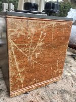
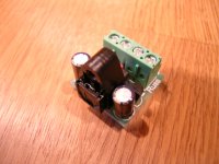
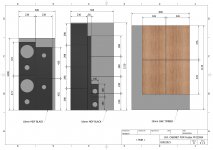
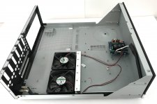
The base is probably the easiest part of the seismic platform to build. It is simply 2 square pieces of ¾” particle board with a piece of 1-1/2” thick soft foam rubber sandwiched in between. The dimensions of the boards combined with the characteristics of the foam determine the natural horizontal resonance frequency of the system. The total weight of the stand plus turntable, spread over the area of the boards, was just below the ‘crush’ strength of the foam. Under normal conditions the foam is uncompressed, and the seismic platform stands neat, straight, and rigid, but provides just the right amount of ‘give’ when things start shaking. It was stable under all conditions, and there was never any danger of toppling over with the heavy turntable on it.


I procured the parts ‘before internet’, got the die ejector pin for free from a relative who worked in the tool & die industry, and I don’t remember what I paid for the LBB’s. I did some web searching and found that Thompson still makes the same LBB’s I used, and I found an online source for die ejector pins. Links for these are posted below. Unfortunately for the DIY’er, I don’t see any other way of building and tuning one of these except by trial and error. From my experience, for the system to work as advertised, it is essential to get the natural resonance frequencies for the vertical and horizontal movement well below the natural resonance frequencies of the turntable suspension, and I would say the lower the better. Another essential point to be mindful of is that the diameter of the shaft or pin you buy must be no larger than the specified internal bore diameter of the LBB. The movement of the pin in the LBB’s must be substantially friction-free. A tight fitting or oversized pin will pre-load the bearing, and the resulting ‘sticktion’ would be a deal breaker for this application. Ideally the pin would be 0.0005” undersize.


Damping: The inherent self-damping properties of the foam and the light grease used in the LBB’s turned out to be ideal. Less is more - I would not try any of the gel-foams or memory foams available today, nor would I intentionally try to add damping to the system.


Areas for improvement: The only design deficiency of any consequence that I encountered was the lack of a ‘rotation restraint’ mechanism. The platform will exhibit a damped oscillatory yaw that dies out in a few cycles (winding and unwinding of the coil spring) if you apply a heavy hand when cueing up a record, but this is avoidable if you use a light touch and poise. I never bothered to do anything about this, but I have a few ideas if anyone wants to pursue it. As far as I can see, the seismic platform should work with non-suspended turntables as well, although the choice of system natural resonance frequencies may be governed by different issues.


Links:
Ejector Pins buy online at Plastixs.com


http://www.thomsonlinear.com/websit...ar_guides/linear_bearings/precision_steel.php


Ray K

Attachments

  • 1 TT Stand-cad V.jpg
    1 TT Stand-cad V.jpg
    93.6 KB · Views: 958
  • 2 tt stand view.jpg
    2 tt stand view.jpg
    442.8 KB · Views: 936
  • 3 tt stand closeup.jpg
    3 tt stand closeup.jpg
    504.2 KB · Views: 911
  • 4 Assembly.JPG
    4 Assembly.JPG
    302.2 KB · Views: 893
  • 5 Die Pin.JPG
    5 Die Pin.JPG
    301.8 KB · Views: 864
  • 6 Top Lin BB.JPG
    6 Top Lin BB.JPG
    272.4 KB · Views: 417

ICEPower Voltage Selection Jumpers

For anyone who purchased the Parts Express ICEpower modules, all six of mine are missing the voltage selector shunt.

I just ordered them from Mouser, but DigiKey has them too. They appear to be AMP 826853-1.

I'll update when I have them in hand. The tech drawings are terrible and I could not immediately find pictures or drawings for the mating pins.

Best,

Erik

Folsom LOFI PCB's (Transformer board) & DC PCB's (PSU boards)

*******NEW PRICES********

Link To Parts and Build

Hey Everyone!

I want to get a GB started for these. The reason I've come up with them is because there is an utter lack out there for PCB boards that are great for small devices & signal operation. You can buy very large PSU items. You can buy regulators, but there is very little out there for a simple high quality rectifier board w/ good parts, and there are not any PCB boards for the fantastic Hammond 229 (especially with high compatibility for voltages). So now I've got some designs that are good enough that I want to use them, so I suspect others will too.

The LOFI: Low output, filtered input. It's kind of a "wad" of iron with two iron devices mounted to it.

-Hammond 229 (48va only) transformer for small chipamps/classD/headphone/signal devices. Chosen because it has great leakage that makes it act as an RF filter. It has been popularly seen with Peter Daniel's DAC's and other high end devices. It has enough juice for a lot of projects, even multiple signal devices.

-PCB board is good for 115/230v with series or parallel secondaries.

-Voltages series 10-56VAC

-Voltages parallel 5-28VAC

-Multiple X caps in CFC config on the input from AC

-CMC/DMC from Coilcraft, P3717-AL (w/ resistor bypasses that work to dampen line problems that can and do occur)

-RC for primary/post CMC tuning

-Uses full copper pours throughout


LOFI.png


DCS1 and DCS2: (Direct Current, Small, 1/2 pole) Simple copper pour based PSU boards.

DCS1 is a single pole.

-TO-220 compatible for diodes (such as MUR860) but has marking's for other diodes.

-20mm snap caps, designed to be compatible with the ever fabulous Nichicon KG (these are superior to FC and FM by a lot).

-pre-diode filter cap vias

-pre-diode RC w/trimmer mounting capability for tuning RC

-discharge resistor placement

-CFC cap configuration

-copper pours throughout


DCS1.png


DCS2 is dual pole.

-TO-220 compatible for diodes (such as MUR860) but has marking's for other diodes.

-20mm snap caps, designed to be compatible with the ever fabulous Nichicon KG (these are superior to FC and FM by a lot).

-pre-diode filter cap vias

-pre-diode RC w/trimmer mounting capability for tuning RC

-discharge resistor placement

-CFC cap configuration

-copper pours throughout


DCS2.png


What I need to make the GB happen. First off I'm going to do a small test print to confirm fit is good enough with the 229, as I don't want to order a bunch of these just to find out they're incompatible. So it'll take a couple extra weeks. My experience is some of these things can surprise you a bit. Here's the price list and quantity needed for printing. *******Due to interest in price I've decided to go with a different PCB printer whom has a good reputation and deliver a decent aesthetic finish, but not as nice as the 7297 & Antipole*******

LOFI: $10ea, orders met
DCS1: $5ea, orders met
DCS2: $5ea, orders met

Shipping depends on country, general for USA small envelope $3. If you order a bundle I will just go to a USPS priority box at $8. Inquire for international (Europe is mostly $15 in a small padded envelope. I don't know why but I can't seem to get a decent deal at my USPS, and sending in a paper envelope is an excellent way to never get them)

mlundy57 2,2,2
BRN 2,1,1
PI 4,4,4
gwrskien 2,0,0
miaminikko 1,1,1


Example Pics:

unnamed33.jpg


unnamed222.jpg


Proximity possible with DCS boards:

shortstack3.jpg

Needs some education - Phase splitter clipping

Hello, hope you are all well and safe, I've been listening with pleasure to my amplifier and now it is time to put him back on the workbench.

I am not fully driving the output tubes, the pentode pre-amp output goes easily to a Vpp of 150v but as soon as I hit Vpp input of around 34V (+/-17V) on the phase splitter it clips.

Does anybody have some suggestions on how to modify this ?
The Anode of the Phase splitter Triode is at 322V and the Cathode at 16.4V

It is a 6U8A tube and I tested with the negative feedback disconnected.

I have attached a diagram.

Attachments

  • Schematics.png
    Schematics.png
    238.3 KB · Views: 175

Plate temperature measurement

Hi all,
I will start admitting I may have been following a white rabbit passing by a little too far. Maybe. However:

I have recently restored/rebuilt a tube amplifier (it happens to be a guitar amp, but you'll see in a moment that won't make much difference to this question) and as I was checking it was all rebuilt well, I set up the bias levels and took a quick look at temperatures of various components all around the amp. This I've done relatively casually using a FLIR i7 thermal imaging camera (a very fun device). I'm a bit fretty because I used a heater wiring that has insulation in PVC and I was concerned it might have heat trouble.

As I was looking around things, I noticed that the plates of the output tubes (a quad of 6L6GC's) read as having a hot spot of approx 160C near the center. The idle current is 40mA and the center tap of the output transformer is 450V, so that the plate is dissipating 18W at idle.

Now the question: if I understand correctly, the only way the plate has to dissipate 18W is to radiate heat away, because the vacuum impedes convective flow, and the pins will do some conduction, but not enough to worry about it.

Indeed the FLIR says the pins on the socket are at approximately 37C, some 15-20C above ambient, but not much heat flow there.

However, applying Stefan-Boltzmann's law to the plate body, it seems you get a dissipation rate of about 5.5W, which really makes no sense to me.

Here's my reasoning:
- heat dissipated is \sigma T^4 [W/m^2]
- \sigma ~= .85 (which I think is high as an estimate, because the plates are dark, but far from black, and eyeballing them they don't look very rough)
- T = 160C = 440.15K implies we get 2128W/m^2
- the area of the plate on a 6L6GC is approx 32cm^2: it's 32mm tall, and seems to be approx 50mm wide if you sum the width of the front, side and "stitching" surfaces, then double for front and back
- the glass will absorb some IR for sure. On the one side you'd think the manufacturer goes out of their way to minimize this effect, on the other maybe they're just using moderately priced glass after all. The expectation is that the envelope will then do a combination of radiation (small, it's very shiny, and shiny things have low \sigma's) and convection through air

Some fine print:
- when computing the plate area you only need the external facing surface of the plate, but not the inner one. That one radiates onto the inner side of the plate opposite from it, which then absorbs it.
- Whatever reflection is left from said inner surface goes back to the emitter and so on. This is like a radiation furnace. There will be some heat escaping top and bottom, of course, but I doubt that'll be more than say 20% (the micas tend to be lightly coloured, and seem to stay much colder judging from the FLIR's reading)
- Note that using the full area as if it was all at peak temperature is also an over estimation: there is no way the "stitching" sides are anywhere near this hot, and even the plate "proper" has a clear temperature gradient across it, about the shape you'd have in a red-plating tube. This is expected because it's where most of the electrons actually hit it, and I'll bet a major component of the gradient is actually heat conduction in the metal
- about the glass: the emission spectrum can be plotted here: at 311C the peak is at 5um, at 170C it's maybe closer to 6.5um. Judgin from this plot, around 5-6um the absorption is just under 5% per mm thickness (maybe 4%?). I haven't checked but I doubt a 6L6 has an envelope thicker than 1 mm


It seems that to radiate away 18W you'd need a plate that is at an *average* temperature of 311C (likely more, because as I said, I don't believe the \sigma estimate is low enough).

Can anybody explain this? I really feel like I'm missing something obvious here.

Thanks for whatever insight you might share

Scope use/timing question

Hi all, hope this is the right forum for finding help with a measurement I'm trying to make with a scope.

I'm sending a one-cycle pulse to a speaker, and trying to measure the time delay as picked up by a mic set up 1-2 mm from the dustcap.

The speaker is a little TC9, so there's maybe 1.5" at most from mic to voice coil.

I would expect the timing between the pulse and the signal from the mic, to be the very short distance mic to speaker....maybe 0.1ms or so.

But i get close to a full millisecond, which is over 12 inches of distance.
And simply can't figure out why.

Here's the scope trace. Horiz grid is 0.5ms per division.
First peak is the pulse signal, second is the mic's.
scope pulse time.png

Further details of test setup, if that's where the devil is:
Signal from arb generator into Ch1 of mixer, which is sent to amplifier and speaker.
Signal from mic into Ch2 of mixer, summed with Ch1 , and sent to scope.
Pulse is a single 1kHz Gaussian burst.
The mixer doesn't appear to be introducing any delay between Channel's summation.

Thanks for any help...I'm really scratching my head why the delay is so long.

Amber Series 70?

I'm know just enough about electronics engineering to get myself in trouble, but I own this amplifier and it's been sitting for years as I have moved from solid state to, first Tripath and now higher powered Sure Electronics boards. I will never go back, however, I do have a question for those far more educated than myself.
This amplifier(Amber) is based on the Lm391 chip, and sounds wonderful, is this amplifier a direct precursor to the gainclone or exactly where does it fall in the progression toward where we are now in regards to 'chip-amps'?
Second question, in regards to this chip not having thermal overload tracking, would fitting a basic heatsink on the IC be a logical upgrade?

Bad MOSFET mystery

I'm working on a project and I have a bunch of DN2540s (both TO220 and TO92) and IRF9610s new from Mouser in protective packaging. Last week I got a Peak DCA75 tester and I was surprised to find that several of the MOSFETs read as defective.

With a DMM, the most telling sign is the bad DN2540s read kilohms or tens of kilohms from gate to drain while the good ones read open-circuit.

The more I play with them, the more failures I have. It's cold and dry here right now. I have a Velleman antistatic pad on the bench but no wrist strap. I try to sit still and keep my hands on the mat and the antistatic bags but I guess that's not enough.

The weird thing is, I can hook the DN2540s up with a gate-to-source resistor -- making a current source -- and they bias up at the expected current.

I assume I've blown the gates with ESD to a sufficient degree to upset the component tester, but not badly enough to completely fry the transistors. I plan to bin the parts, but I'm just curious about the mechanism. In particular, I worry about the remote possibility there's something about the tester and my PC that's causing the failures. The tester otherwise seems to work perfectly. I do understand electromagnetics and the fundamentals of MOSFET construction.

Mainly I'm wondering if people have had similar experiences and what the best way is to prevent this from happening in the future. Because the transistors seem to function after a fashion, I'm worried about ending up with a degraded circuit that doesn't appear obviously broken from basic test measurements.

-Henry

YBA Integre Passion 100 burnt resistors.

Hi Alan

I have an YBA Intergre Passion 100 which seems to use the same schematic. I have a problem that R99 (10 ohm) blew up. The resistors are marked YBA 10R with no power rating. It’s about the size of a 3W metal film resistor. I suspect it could be metal oxide type.

Could you help me to identify the type and rating of this resistor? Or could your recommend some specific resistors for replacement?

Only 2 resistors out of 4 blew up. The amp is still working but it sound a bit distorted to me.

I am not even sure that the schematic is the same or not since my amp has 2 x 10R resistors per channel connected to ground at one end.

Thanks in advance!

You will be very disappointed, the distortion is going to be high. Only 33ohm degeneration resistor, no cascode on LTP, no darlington VAS and 2EF. That's the hallmark of a cheap amp.

To me, distortion means nothing. It's the sound. I don't care to even debate tube or SS. It's the sound and that's the only thing that matter.


Current is push pull between P and N. You have P on one side and N on the other side. Current travel the whole length of the board. With P N alternate, the current loop is only on each pair. This is local current loop. This is particular important if you have thin trace.

I worked with MOSFET for years, not on audiophile. If it is done correctly, they are very rugged. But if you are not careful and leaving parasitic at the drain and gate path, they tend to oscillate and burn the gate very fast. They die a very quiet death. You turn on, it just die.....cold. You measure, everything shorted. Seen this too often already. Layout is very important and you have to treat it as RF device.......as they are. They are being used in RF power amp by making use of their Cgs capacitance for tuning. That's the reason I decided against using MOSFET myself even with all the supposedly advantage and stay with BJT. The last one I burn was used in my power scaling design for a tube guitar amp last year. You leave the lead a little long, you might get into trouble. By long, I mean 1", not a few inches.

You cannot use zener, transorbs to clamp the gate, it's internal. we tried it all. Only cure is short thick wires. You treat it as RF device, they last and last.

Attachments

  • EFBECDA4-8575-4125-91C2-C8A3D1B8EB64.jpeg
    EFBECDA4-8575-4125-91C2-C8A3D1B8EB64.jpeg
    425.5 KB · Views: 305
  • 9080605E-DD41-4A2F-8574-FDE8179D402B.jpg
    9080605E-DD41-4A2F-8574-FDE8179D402B.jpg
    968.3 KB · Views: 363

Board placement

Folks, I am building a paraphase driven 6V6 power amp into an old Knight PA chassis (that I quite like the look of). This happens to have just the right amount of octal sockets in it for my build (which avoids having to drill new chassis holes), but converting this originally mono chassis into a stereo unit (with the salvaged Scott iron I am using) limits very much where I can place my transformers. Underneath I am faced with having to mount my “pre-amp” turret board (basically all of my front end components from the grid leak resisters through the coupling caps, AC balance control, etc) directly under the power transformer.

Bad idea, or really not such a big deal in practice?

Justin

Power Dissipation

Hello, I'm kind of new to designing and building speakers, and I am currently working on my first project. I am making two two-way bookshelf speakers on a limited budget. I am using the Dayton Audio DC130B-8 (woofer) and the Dayton Audio DC28F-8 for my tweeter.

I am currently using Xsim to design the crossover and I ran into a question/problem. When I look at the power dissipation graph (amp is at 40watt) the curves for the tweeter and the woofer are both over their rated RMS. And when I set the amp at 100 Watt, both driver exceed their max Watt rating.

I was wondering if that was an issue and that I was running the risk of blowing out my speakers, or if I was missing something, or how I could fix this issue (without exploding my budget).

Thank you so much for your responses in advance🙂

Attachments

  • 40 watt.png
    40 watt.png
    289 KB · Views: 132
  • 100 watt.png
    100 watt.png
    258.4 KB · Views: 134
  • DC28F-8.png
    DC28F-8.png
    176.2 KB · Views: 137
  • DC130B-8.png
    DC130B-8.png
    193.9 KB · Views: 126

6-bit Relay Ladder attenuators preamp w Sub out

I am making a simple preamp with
-6 bit relay Volume attenuator
-Class A Line driver output stage
-2 x stereo selectable inputs
-1 x Stereo subout @ fixed 85hz linkwitz Riley low pass
-rollable opamps for filters.
-Apple remote controls
-0 to +12dB Sub Gain.
-chili red 1602 display

pack with a beautiful chili red Chassis. 😀


Target for two large 18inch UM18-22 @ 14cf sealed box.

Attachments

  • IMG_20210221_220732.jpg
    IMG_20210221_220732.jpg
    248.9 KB · Views: 153
  • IMG_20210221_220838.jpg
    IMG_20210221_220838.jpg
    310.2 KB · Views: 142
  • IMG_20210221_220945.jpg
    IMG_20210221_220945.jpg
    115.3 KB · Views: 143

Strange sanyo caps

64535-DF9-8761-493-B-B9-D5-44-F6-A3373-E24.jpg
Today I got a second nobsound tpa3116 which I have no complaints about but when looking at the caps inside I noticed that they have different style vents.
Both amps have the same sanyo wx 470uf 35v caps, same sleeve, same values but different vents. Usually vents are the same within one brand and within a certain range of values, so does this tell they're not genuine ? Wouldnt be shocked as its a chinese product after all but maybe some can explain?!
all the best
Arne

Pal-nuts

Looking for some dimensions on a pal-nut that fits a standard potentiometer. I believe the threads would be 3/8" x 32. Picture attached. What I need is the *internal* flat to flat distance. [would be the outside flat to flat - 2x material thickness].

Attachments

  • Palnut.JPG
    Palnut.JPG
    16.5 KB · Views: 235

Turntable physics questions-velocity of tangential arm?

What velocity must the cartrige move at in a tangential arm on an LP? What is the formula for determining the ideal weight of a tonearm, given the cartrige weight and compliance? What is the formula describing the arc a pivoting tonearm makes? What is the range, median and average coefficient of friction for a vinyl record? I know the stylus and program material affect it, but there must be a general range. What is the force vector (in general of the groove, in Newtons, pulling a tanegential arm towards the center of the table? Tho horizontal force vector, if you will. If anyonw knows the answer to these questions, I would be greatly appreciative. For those of you without the science. I appreciate your experience too. What tonearm weight would you recommend for a cartridge weighing 5.3 grams, with a compliance of 15 cm/dyn and a tracking force recommendation of 1.8-2.0g

Linkwitz Transform: Attenuator or Booster?

Is the Linkwitz Transform circuit of ESP Project 71 a bass booster or a mid-range attenuator?

1. If it's a bass booster, I can plug it in after the active-crossover where only the subwoofer signal is left.

2. If it's a mid-range + hi-freq attenuator then it will have to be plugged in before the crossover since it will need to work on the full signal.

Any help is appreciated.

A Noob Valve Preamp Build?

I finished an Aleph-J amp which had a pretty comprehensive build guide and didn't expect too much from the assembler in terms of in-depth calculations or even too many choices which allowed me and I suspect lots of others to build this amazing amp and many other amps.

I run it using a cheap Monoprice integrated amp which happens to have a line out from the valve preamp and I am pretty happy with the sound. However I would really like to make a good quality valve preamp[line stage] and even a phono one as well as mine is a tiny solid state Rega.

OK here's the thing. I have spent day after day reading through various preamp threads but I have not found one that documents the build completely in a way that makes it possible to just buy the parts and build it. Even the Aikido has so many choices that I was left confused and would need advice to choose the various components and still more advice to choose the specific transformers.

Every single thread goes into interminable arguments about all kinds of variants many of which are only measurable with pro equipment and the knowledge required exceeds my very newly acquired interest in this field. I could probably build from a schematic but then I get crossed wires about how many transformers are needed and all the talk of valve substitution and it goes on and on and on and the more I read in a thread the less inclined I am to get halfway into one of these projects only to find I can't get through it or fix too much hum or something.

So I'm actually begging for someone to do a full build guide for a 12B4 or something sweet and simple, including the whole process, power supply, BOM and layout whether or not there are circuit boards available, but using components that are easily purchased.

I believe something like this may be in the pipeline in the DIY shop which will then no doubt have an excellent build thread by 6L6 and we'll be able to join the ranks of the experts at least in being able to have this stuff to listen to.

But I'm putting this thread up here in the hope that some alternatives are already about that apply to this beginner level.

Cheers.
  • Like
Reactions: DblAA

Phonic MAX1500 repair/ questions

I have aquired 2 Phonic MAX1500 amps for nix.....one is working and one has a few gremlins that need sorting. Anyhoo I downloaded the schematic from Phonic but am a bit concerned about some component values which seem out of place. I thought peeps like those who have read this far could take a look and see if my cheese has slid off the cracker or am I on the track.

Components concerned is in the protection circuit for the output transistors. Specifically resistors R327, R328 and R323, R324.

Everything looks nice and symmetrical except for these few resistors on the bases and emitters of Q308 & Q307. Is this ok???

Also while I'm here and have your attention.....is it odd that Q303 is a darlington??

Attachments

9V Circuit to 18V?

Hi there, I'm wondering if I could get some advice on changing the following circuit from 9volts to 18volts- advice on generally how difficult it would be, components that would need changing, etc.

I posted on this forum years ago, and with the help I got here, built and have been using the following circuit ever since: https://www.diyaudio.com/forums/ins...film-buffer-amp-combo-guitar-electronics.html

But recently I've upgraded my piezo film sensors to GraphTech ghost pickups. Overall it's a great upgrade, but now I'm getting a bit more of a "quacky" piezo sound. So the main intent here is to get rid of that, with the idea being that upgrading to 18volts will provide more "headroom" which will bring down the quack. I'm open to ideas if anyone has anything to say about this whole assumption.

I've attached the circuit below:

Attachments

Acoustat Spectra22 VS Spectra33

I love my Spectra22. I use them in a smallish 12 foot by 16 foot room. My main complaints are: Lack of punch on some (rock) music, lack of bass (punch), and a failure to "pressurize" the room or achieve high volume levels.
I have the opportunity to purchase a pair of Spectra33 speakers. They would be a tight fit in my room but I could make it work (the edges of the outside frames would be within an inch of the sidewalls).
Would this change resolve my complaints? Do the 33s have more bass and punch? Or would it just be more of the same?
The alternative is building a pair of dipole subwoofer and running them from about 40hertz down on top of the full range Spectra22. This would be fairly costly and time consuming. I do not want the signal to the Spectras going through a crossover.

Behringer EP2500 feed through/daisy chain linking

Hi All, apologies if this is general knowledge, but I'm damned if I can find it, and Behringer technical help don't know either! I wish to use three EP2500 amps in bridged mono driven by one XLR output.

Can a single crossover output feed the first amp and out to the second one and thence to the third?

The parallel mode and using the TRS 1/4" jacks come to mind, however the manual states on one page that the parallel switches must be 'off' in bridged mode, yet on another states that if they are 'on' then the signal feeds through. I'm not in a position to physically test this with my amps at present and was posting to see what other folks do - I am trying to avoid a distribution amp! Cheers, Carl.

Also apologies if posted in the wrong section - which I believe I have...🙁

Single-225 with Fostex FF225WK

I have here a new pair of 225’=s (only used for a test couple of months ago) and like to build a simple speaker cabinet for them.
In the manual of Fostex there is shown a standard bass reflex cabinet for this driver. From other projects I have some surplus materials and therefore very useful for this relative small and simple project.

Attachments

  • $_86 (1).jpg
    $_86 (1).jpg
    99.9 KB · Views: 430
  • $_86 (2).jpg
    $_86 (2).jpg
    67.4 KB · Views: 402
  • $_86.jpg
    $_86.jpg
    98.7 KB · Views: 447
  • PDFtoJPG.me-1 (5).jpg
    PDFtoJPG.me-1 (5).jpg
    715.5 KB · Views: 545
  • PDFtoJPG.me-1 (6).jpg
    PDFtoJPG.me-1 (6).jpg
    397.4 KB · Views: 482
  • PDFtoJPG.me-2 (2).jpg
    PDFtoJPG.me-2 (2).jpg
    474.2 KB · Views: 273
  • PDFtoJPG.me-2 (3).jpg
    PDFtoJPG.me-2 (3).jpg
    362.3 KB · Views: 281

Armrest for Gray Research 212 Tonearm

Hello friends!
I have been recovering my Gray Research 212 tonearm for a long time.
Faced some problems, but still managed to solve some of them.
At the moment, I need an armrest, unfortunately, I cannot purchase it, and I made a decision to recreate it on a lathe. I ask you, if anyone has this armrest at hand, publish the dimensions. Thank you in advance!
Cheers!

ESP P113 volume control problem

I've just built Rod Elliott's P113 HPA using my own PCB and have a problem with the volume control. I'm using 300ohm Sennheiser HD600 headphones.

The pot only really gives any output at the very last fraction of its clockwise turn. There is some sound before that, it stays relatively constant at a low level before kicking in. I had the board connected to an Alps RK27 20K log pot, I then swapped it out for an Alps RK09 10K pot but the result is the same. I've seen this behaviour mentioned elsewhere on the forum in relation to 'passive' preamplifiers and described thus:
It is the effect of turning the volume control and it stays really quiet until close to the end where all the power seems to be in the last "hour" of the volume control between 4 and 5 o'clock.
If I bypass the pot, the amp works fine and there is a nice gradual increase in volume when I use my source volume control (Samsung Galaxy S7).

Any advice please?

Willing to pay someone for amp advice

Simply put, I'm TOO ignorant about all the things of different amp designs, and do NOT have a clue how to determine the sound quality differences before buying them. So far I e been unhappy since far with the Wondom boards I've tried. They have everything but musicality. Zero hint of an organic sound. They remind me or Pro amplifiers in that regard.
I want a minimum of 200 w/ch at 8 ohms. I MUST have mono block for my application.

I am now looking at Hypex Ncore and Purifi
I need a smallish amplifier I can mount directly behind the loudspeaker. I need the proper power supply voltage, but I know NOTHING about power supplies. So I assume I will have to use the one made for each unit, unless someone steers me differently. BUT I NEED the amp to have at least a little musicality to it. I don't care which technology gets me there.

I have asked for help here before, and have not received enough help. If someone KNOWLEDGEABLE wants to help steer and educate me a bit, I WILL PAY THEM via PayPal.
If you're willing to post the info here, where others can benefit, I will pay extra for that.

My system if needed, is such. My source is mainly FLAC files played via a laptop, sent through an external Sabre DAC, and into the two individual mono amplifiers which I need.
My speakers are numerous high end DIY speakers, both 4 and 8 ohm. Nothing overly difficult to drive though. A pair of Carreras, a pair of Bordeaux, my own design using a 10" mid with AMT, and bass cabinets with Kappalite 12" woofers. All speakers above 89 sb efficiency. Oh, this is important... I do NOT know any of the model numbers and abbreviations you fellows more knowledgeable use. Please, they will not help me without manufacturer names or links. Saying, grab a TX99 with overhanging cap structures and combine it with a hg1766 will NOT help me.
So please help a guy out, and make a bit of spending money for your pockets. Thanks

Large project chassis for SS amp - $40

This is the chassis from a Niles music server.

It measures approx. 17.5 x 17.5 x 5.5" (or 6" with the feet).

It features a nice front-mounted power switch with LEDs and dual 12V DC muffin fans. There is a cut-out for a toroid power transformer.

It would be a simple matter to make a new panel for the rear; paint over the logo in the front; and then you're in business.

Attachments

  • Niles complete.jpg
    Niles complete.jpg
    501.1 KB · Views: 310
  • Niles open.jpg
    Niles open.jpg
    939.1 KB · Views: 313
  • Niles rear.jpg
    Niles rear.jpg
    587.4 KB · Views: 304
  • Niles side.jpg
    Niles side.jpg
    598.5 KB · Views: 292

DIY S&B TX102 TVC preamp with Silver windings, Seiden switches

Put this preamp together some years back and have been in love with it ever since.

Silver winding S&B transformers, Seiden switches, remote control. Works great and wouldn't be selling if I wasn't going to an active 3 way system.

TVC transformers with the silver winding retail for around $1700US a pair these days, and the Seiden switches were a few hundred as I recall. Would like to get around $1500US but will entertain reasonable offers.

Thanks.
Projects by fanatics, for fanatics
Get answers and advice for everyone wanting to learn the art of audio.
Join the Community
507,774
Members
7,887,977
Messages

Filter

Forum Statistics

Threads
406,210
Messages
7,887,977
Members
507,774
Latest member
pete2000