I was reading through old diyaudio threads when I came across a name I remembered, and a circuit invention I played with about thirty years ago.
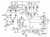
In 1988, Mr. William Chater published "A 40W All-MOSFET Power Amp" in Audio Amateur. I was quite taken with it at the time. Not the all-MOSFET design, but the 4-opamp servo he was using to set the bias current of his output transistors. I'm attaching a picture from his patent, which is for the servo, not the amp.
http://patft.uspto.gov/netacgi/nph-...50&s1=5055797.PN.&OS=PN/5055797&RS=PN/5055797
I adapted that bias servo to a triple-EF design I was working on at the time. It's really a very cool idea. The minimum of the voltage across R44 and R45 is proportional to the idle current, regardless of signal level. Let's sense the voltage across those resistors, and detect and hold the minima with a large enough time constant to control the DC bias.
Ultimately, I found the bias servo to be impractical. The reason is that R50 - R53 must be very closely matched to have enough common-mode rejection for this to work. I built it with 1% resistors for R50 - R53, and initially it seemed to work. However, when I hooked it to a loudspeaker, it fell apart. With a resistor load, zero-crossing of the current and voltage coincide, so not much CMR is needed. With a reactive load, A1 is trying to sense a very tiny difference voltage on top of a very large common-mode signal. Bias jumped all over the place, and I was afraid the amplifier was going to burn up.
I replaced R50-R53 with 0.1% resistors, and that helped a lot, but bias was still kind of jumpy with certain music and certain speakers.
I long ago had an idea for how to fix Mr. Chater's bias servo, but I'm just now getting around to trying it. It's a tricky circuit. Special attention has to be paid to the initial conditions of C26 and C20, and the relative time constants of the min detector and the integrator.
In 1988, Mr. William Chater published "A 40W All-MOSFET Power Amp" in Audio Amateur. I was quite taken with it at the time. Not the all-MOSFET design, but the 4-opamp servo he was using to set the bias current of his output transistors. I'm attaching a picture from his patent, which is for the servo, not the amp.
http://patft.uspto.gov/netacgi/nph-...50&s1=5055797.PN.&OS=PN/5055797&RS=PN/5055797
I adapted that bias servo to a triple-EF design I was working on at the time. It's really a very cool idea. The minimum of the voltage across R44 and R45 is proportional to the idle current, regardless of signal level. Let's sense the voltage across those resistors, and detect and hold the minima with a large enough time constant to control the DC bias.
- A1 senses the difference across R44 & R45.
- A2 and A3 sample the minimum of that difference. A2 quickly samples the minimum, and R47 lets it decay (very) slowly.
- A4 is an integrator, of course. The bias control signal must be well-below audio frequencies. A4 sets the current of TR5, which sets the current of Q6 and Q7. Q6 and Q7 set the bias of Q11 and Q12 with currents into R41 and R42.
Ultimately, I found the bias servo to be impractical. The reason is that R50 - R53 must be very closely matched to have enough common-mode rejection for this to work. I built it with 1% resistors for R50 - R53, and initially it seemed to work. However, when I hooked it to a loudspeaker, it fell apart. With a resistor load, zero-crossing of the current and voltage coincide, so not much CMR is needed. With a reactive load, A1 is trying to sense a very tiny difference voltage on top of a very large common-mode signal. Bias jumped all over the place, and I was afraid the amplifier was going to burn up.
I replaced R50-R53 with 0.1% resistors, and that helped a lot, but bias was still kind of jumpy with certain music and certain speakers.
I long ago had an idea for how to fix Mr. Chater's bias servo, but I'm just now getting around to trying it. It's a tricky circuit. Special attention has to be paid to the initial conditions of C26 and C20, and the relative time constants of the min detector and the integrator.
Attachments
Are you able to provide a brief walkthrough of the new circuit design? This looks very interesting.
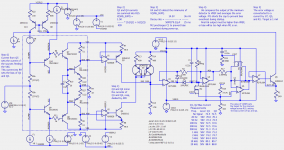
Here's my fix, so far...
I replaced A1 and its impossible CMR requirements with current mirrors U1, Q3 and U2, Q4. Now there is no CMR requirement, because I am sensing on the rails which are (mostly) non-dynamic.
I could do a precision sense on the ballast resistors, but then I'd have to have a +/- 5V supply domain that floats with the output signal. Doable, with bootstrap techniques, but likely to inject something into the audio. There are several less precise ways to sense the ballast resistor voltage, but if it's not precise, I don't see the point of the exercise. Unlike with overcurrent protection, I'm sensing the minimum, not the maximum voltages on the ballast resistors.
The AD8628 I picked because LTspice chokes on my 1st choice--TI's TLV376. Any low Iq, low offset, rail-rail, 5V op amp will work here, and the TLV376 is the cheapest one I found. I might use the AD8628 anyway. The BCM857B mirror is probably the biggest source of error, but R13 and R14 should minimize mismatch.
The minimum detector is much the same as Mr. Chater's. I put in M1 and M2 to set initial conditions to avoid bias overshoot and long start up times.
The amp is running at low bias by 500 ms, is at 95% of full bias at 1 sec, and is fully settled by 1.5 sec. How long do most amplifiers take to settle to their final bias current?
The thing I worried the circuit would not be able to do is keep a consistent bias with full power signals from 20 Hz to 20 kHz. At 20 Hz, decay on the min detector causes an error in the average sensed minimum voltage. At 20 kHz, the op amp U4 may not be be fast enough to detect the minimums. With the values of C and R I've chosen in the min detector, bias is down by about 3% at 20 Hz, but up by 25% at 20 kHz.
Q1, Q2 Bias Current Measurements
Freq. Level Q1 Q2
No Signal 72.5 72.5
20 Hz 50V 70.0 70.1
50 Hz 50V 72.4 72.5
100 Hz 50V 72.5 72.6
200 Hz 50V 72.5 72.6
500 Hz 50V 71.3 71.4
1 kHz 50V 70.8 71.2
2 kHz 50V 74.2 74.7
5 kHz 50V 84.4 83.9
10 kHz 50V 89.1 89.7
20 kHz 50V 88.4 88.8
Consider that bias was going go up at high frequency anyway, due to 10uF at C3. Also consider that actual music never has high power, high frequency zero crossings. The fundamentals are usually much lower.No Signal 72.5 72.5
20 Hz 50V 70.0 70.1
50 Hz 50V 72.4 72.5
100 Hz 50V 72.5 72.6
200 Hz 50V 72.5 72.6
500 Hz 50V 71.3 71.4
1 kHz 50V 70.8 71.2
2 kHz 50V 74.2 74.7
5 kHz 50V 84.4 83.9
10 kHz 50V 89.1 89.7
20 kHz 50V 88.4 88.8
Attachments
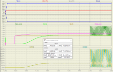
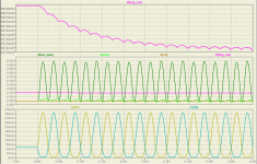
Here are some plots from the .tran. Supplies start at 0V and ramp up in about 100 ms. Then, it's off to the races. The 1st plot shows the startup with no signal until the 2 sec mark, when a 10V, 20 Hz signal is applied.
The 2nd plot shows a close up of the circuit operating with the 20 Hz signal. The green V(min) signal shows the decay of the min detector with a 1.1 sec time constant. The magenta signal shows the integrator responding to this decay (which looks like a bias current that's too high) by dropping it's output slightly, which reduces the bias, settling to a lower value in about 400ms.
So, if heating or whatever, changes the bias, this circuit responds withing 1/2 a second. That time constant could be made slower, but I'd be afraid of interacting with the thermal time constants.
There's nothing to trim in this circuit, once you have the bias you like, all subsequent production units should have a bias within 5% of that value (provided 1% resistors are used throughout).
Attachments
I expect the original circuit to get less sensitive to resistor tolerances when the differential amplifier has a large gain, so R53 = R52 >> R51 = R50. In the limit, for R53/R51 -> infinity (which is utterly impractical, of course), it is just the op-amp limiting the CMRR.
Did you use a large gain?
In any case, your fix is far more elegant.
Did you use a large gain?
In any case, your fix is far more elegant.
You would be wrong about that. Any error at all in the resistor values lets the common mode come crashing through. A little math shows that. The op-amp CMRR is orders of magnitude higher than what is caused by resistor mismatch.
The common-mode voltage can be as high as the supply rails, say +/-50V. The difference mode voltage that you are trying to resolve is typically 50 mA * 0.22ohms * 2= 22 mV. It is difficult to resolve a 22 mV difference on a 50V common mode signal.
I recall using a difference mode gain of 25, to make the minimum about 600 mV. It was a long time ago, and I've lost the notes.
In any case, your fix is far more elegant.
Thanks. I've put some thought into it. The current sense mirrors will be powered by shunt regulators hanging from the supplies. (cheap!) The shunt current will go down to discrete +/- 15V series-pass regulators to provide supplies for the min detector and integrator.
By the way, what's the purpose of R26 and R27 in your circuit? Ensuring that the output transistors don't go up in smoke when someone suddenly applies a large high-frequency signal, distortion compensation or something else?
The MJL3281 and 1302 actually are just 1 of 4 output transistors in parallel. That's why the load resistor is 32 ohms. 4 x 8. R26 and R27 are ballast to help with current sharing.
I was privately asked for the .asc file. I thought I should put it here.
Here's the .asc file for the LTspice. Also, you'll need the BCM857BS model. (The BCM847B.lib is not used. Delete that .lib line.
* BCM857BS
*
* Nexperia
*
* Matched double PNP/PNP Transistor
* IC = 100 mA
* VCEO = 45 V
* hFE = 200 - 450 @ 5V/2mA
*
* PIN_ORDER
* 1=E1 6=C1
* 2=B1 5=B2
* 3=C2 4=E2
*
* Model is Nexperia BC857BS, repeated for each device in the package.
*
* The Diode D1, Transistor Q2 and resistors RQ1
* are dedicated to improve modeling of quasi
* saturation area and reverse mode operation
* and do not reflect physical devices.
*
.SUBCKT BCM857B 1 2 3 4 5 6
XQ1 6 2 1 BC857
XQ2 3 5 4 BC857
*
.SUBCKT BC857 1 2 3
Q1 1 2 3 MAIN 0.9607
Q2 11 2 3 MAIN 0.03929
RQ 1 11 561.1
D1 1 2 DIODE857
*
.MODEL MAIN PNP
+ IS = 1.95E-014
+ NF = 1.022
+ ISE = 1.253E-014
+ NE = 1.577
+ BF = 297.2
+ IKF = 0.0831
+ VAF = 41.13
+ NR = 1.021
+ ISC = 1.791E-016
+ NC = 1.183
+ BR = 10.02
+ IKR = 0.02503
+ VAR = 16.61
+ RB = 220
+ IRB = 2.5E-005
+ RBM = 0.9
+ RE = 1.045
+ RC = 0.2657
+ XTB = 1.28
+ EG = 1.11
+ XTI = 2.944
+ CJE = 1.095E-011
+ VJE = 0.6608
+ MJE = 0.375
+ TF = 1.2E-009
+ XTF = 3
+ VTF = 3.813
+ ITF = 0.1208
+ PTF = 0
+ CJC = 5.88E-012
+ VJC = 0.5428
+ MJC = 0.39
+ XCJC = 0.459
+ TR = 8.8E-008
+ CJS = 0
+ VJS = 0.75
+ MJS = 0.333
+ FC = 0.9501
.MODEL DIODE857 D
+ IS = 7.703E-015
+ N = 1.146
+ BV = 1000
+ IBV = 0.001
+ RS = 2.826E+004
+ CJO = 0
+ VJ = 1
+ M = 0.5
+ FC = 0
+ TT = 0
+ EG = 1.11
+ XTI = 3
.ENDS BC857
.ENDS BCM857B
Attachments
- Home
- Amplifiers
- Solid State
- William Chater's "Bias control for power amplifiers," Revisited