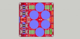
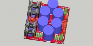
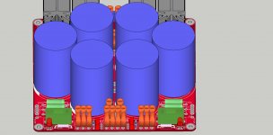
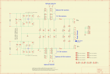
Speaker Protection Board

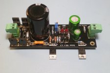
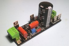
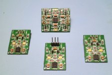
I've designed a simple speaker protection board using the UPC1237 (Unisonic Taiwan is the manufacturer, originally uPC1237 from NEC) that uses mosfets rather than a relay to switch the speaker. The circuit operates from 25V to 75V with some resistor changes (detailed in the write-up), features power up/down muting, DC offset protection and an input to trip the protection on overcurrent (you will need to arrange your own short circuit detection - the board just takes an input for this as a trigger).

There's a presentation with the circuit, BOM and if you want a board, you can buy one off the website.

https://hifisonix.com/projects/hifisonix-speaker-protection-board/

Happy soldering

🙂

See here for where to connect the AC detect input in split power supplies: https://www.diyaudio.com/community/threads/speaker-protection-board.377896/post-7283100

JohnAudioTech JAT501 Build Thread

JohnAudioTech JAT501 Build Thread

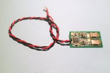
Hi, I ordered a batch of ten JohnAudioTech's JAT501 PCBs from JLCPCB. The Inline double sided version. Made from JohnAudioTech's publicly available JAT501 gerber files.

John, Thank you for your generosity and contributions to the community. Also, much thanks to the anonymous PCB designer. Much appreciated.

Attachments

  • IMG_1959.JPG
    IMG_1959.JPG
    861 KB · Views: 474
  • IMG_1960.JPG
    IMG_1960.JPG
    832.1 KB · Views: 434
  • IMG_1961.JPG
    IMG_1961.JPG
    681.8 KB · Views: 439

Class D amp directly solar powered?

I have a 2x25 Watt class D amp with CS8673 chip.

It can take maximum voltage of 24 Volts.

I have a 60 watt solar panel with maximum open circuit voltage of 22 Volts.

Is it possible to power such an amplifier directly with a solar panel with maybe some filtering capacitor of several thousand uF? Or should filtering be omitted ?

I live in egypt here you have always sun and it never rains.

Anyone tried running a class D amp like this?

Bass chest kick science

When I started getting in diy audio, especially in car diy audio. I was thinking why my powerful subwoofer cand give me a chest kick at all but those very cheap subs from sony, pioneers etc can??
I believe is because of mms! Even if the motor force is high, if the mms is over or at 200gr of a 12" driver, you can't feel the midbass! the cone will not accelerate fast enough because of inertia! A high bl force will reach a high speed cone but won't accelerate fast enough.

I come with this calculation (Bl÷mss) the = needs to be higher than 0.1 for midbass kick feel.(Don't ask me where i found this 😂) 20bl÷200mm=0.1 but even if the equal is 0.1, the mms is too high for a 12, this more calculates if the bl is high enough.

The mms needs to be under 200 for a 12" (150) above 200 for 15" and under 100 for 10" and so on.
If you look at the specs of pa drivers and those cheap *** subs, you can see exactly this(not all of them of course) makes sense.
Basically you need midbass mms with high enough vas to reach 30hz.
Mms is the king.
  • Like
Reactions: Palmspar

Low cost, high performance headphone amp using OPA1656 and LMH6321

An ultra low distortion moderate power headphone amp was designed for use with a phono/line preamp project.
This is the stand alone amplifier board that was developed.
The goal was to provide an unbalanced headphone amp that would produce essentially unmeasurably low distortion at 2v RMS output, could drive headphones from 15-300 ohms, and would operate using the +/15v supply that was used in the preamp.
Specifications:
+/-15v - SMPS is fine. 0.6A per supply rating.
>90dB power supply rejection over the audio band.
Peak output drive current set at 270mA/channel
0.4W max into 15 ohms.
0.8W max into 30 ohms.
0.15W max into 300 ohms.
Stable into any load capacitance.
Output impedance <0.1ohms.
DC offset <2mV.
AC coupled input (0.47u PP cap, 220K ohm input resistance).
1.5Hz - 1MHz 3dB bandwidth.
Thermally protected.
Protected against shorts.
Fault LED indicating overheating condition.
PC board designed using TI guidelines to act as heatsink, and can accommodate 15ohm and higher loads without shutdown at rated power levels.
Stable into any capacitive load.
6dB gain.
10k volume pot can be added.
TH Distortion plus noise @1kHz, 2v RMS output 80kHz measurement bandwidth: <-114dBc (0.0002%) A weighted. Limited by measurement system.
Not appreciably different at 20kHz, not appreciably different for 30-300 ohm loads.

Basically a realization of the TI app note with simulated/evaluated compensation.

Attachments

  • headch.PNG
    headch.PNG
    20.1 KB · Views: 3,515
  • headphone board.jpg
    headphone board.jpg
    130.5 KB · Views: 3,356
  • 0.77w out 30 ohm load just before limiting.png
    0.77w out 30 ohm load just before limiting.png
    201.4 KB · Views: 3,154

Need some help with a Technics A900s

hi.

i have received my second Technics se-a900s, i bought this one defective, the problem is that it is in protect. i had a hope that it could be bad solder points... so i started troubleshooting yesterday and found many bad solder joints... soldered these but nothing happened, so i went ahead and measured some volts on svi 3205, and on pin 3 i found the fault.. 53.2v..so the left channel is defective.. i have an a800s that looks like it has been through a meat grinder so i am thinking of taking the svi 3205 from this one, but i don't want to put it in without knowing what caused the svi3205 to fail. so what is the next step? are there any other components that could have been damaged?

LED Pilot Light - Wiring Confusion

I want to replace the LED pilot light in one of my guitar amps. The power source in the amp is the 6.3VAC tap on the power transformer. The published specs for the LED I want to use are:
  • operating range 5-14VDC
  • voltage drop 2.8V (typical)
  • @ 20mA

I have seen two different ways to connect this. One has the anode of a IN4002 diode connected to the negative lead of the LED and the resistor of appropriate value connected in line on the positive lead. The other way shows the diode connected across the pos and neg leads of the LED, with the resistor inline on the positive lead.

Advice please.

Fountek repair kits

Hello all of you, audio lovers
HNY and so on
I heve a lot of repair kits for Fountek ribbon tweeters. All of models. I'll be able to send it to worldwide, Video of use process see there
Login to view embedded media By the way - this is my audio youtube channel
Regards

Attachments

  • 11.jpg
    11.jpg
    368.8 KB · Views: 185
  • 12.jpg
    12.jpg
    191.2 KB · Views: 184
  • 13.jpg
    13.jpg
    300.4 KB · Views: 190
  • kit8mm.jpg
    kit8mm.jpg
    272.8 KB · Views: 182

ISOBARIC sealed enclosure... Any experiences? Any advantages?

ISOBARIC sealed enclosure... Any experiences ? Any advantages ?

In a project of a quite large 4-ways sealed enclosure, I wonder if going for the isobaric principle for the woofer setion would offer advantages... 🤔

The goal is not to reduce volume, but improve bass extension in frequency response, transient and step response, distortion, by using a tandem of speakers, like this - but larger about the back volume

1718707662867.png


According to many expert authors, combining two identical speakers in that way offers an equivalence of :
  • Z / 2 (connected in //)
  • VAS / 2
  • QTS unchanged
  • FS unchanged

If the enclosure volume remains the same (the common chamber is not counted) for one sealed speaker, or two isobaric speakers, as a consequence the result is a lowering of the QTC, so a better transient, earlier bass cutoff start but smoother and longer slope, potentially giving a better bass extrension.

Any advice or experience in that field ?

Thank you Guys !

T

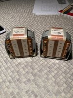
Sansui output transformers

Hi everybody, I have a pair of Sansui radios, a SAX100 and a SM12A, both rather obscure but very interesting probably not only because they are single ended 6BQ5 amps. Not much difference between the two, the SAX has a transistor phono input, the other one has a simpler power supply but two AM tuners for early stereo simulcast and a dual magic eye.

Now the problem is that I have found some differences in the output transformers. I was measuring them without much care for the values, just to check they are the same in each radio and found they were not.

The SAX has one transformer with about 240 Ohm DC resistance primary (and about 7H inductance) and the other transformer has about 200KOhm DC resistance and doesn't give an inductance reading (Peak LCR meter) - I get some negative value with a question mark. Secondaries check out, they are all the same, and make sense.

The 12A exhibits the same ailment. One of the outputs has near identical parameters with the first one above (approx 240Ohm DC resistance and 7H primary) whereas the other one has 500KOhm primary DC resistance and reads gibberish for inductance. Secondaries of both replicate almost to the decimal the values of the other two.

What gives?!

Are the two trannies with high DC resistance cooked? Or is the LCR meter out of its depth?

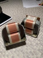
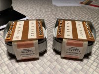
A little bit of investigation revealed the transformers used in these radios are the same part so they should be swappable (my intention for the moment). Externally they look identical, and after a little bit of cleaning I found under the grime the same labels on the transformers (all also have "5.2K" written on the primary side plus terminal labels).

My gut feeling sez the two transformers with "normal" parameters are still good and I plan to use them to restore the 12A (the SAX is worse for wear), but I would like to know if I can recover the other two. Are they dead? I mean do they need a rewind? Not going to throw them away, but would be good to know.

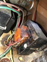
Would be interesting to know how they managed to go high resistance, because I thought they would either go open or short. Not sure how a wire can increase its resistance. There are signs of heat stress, the outputs are right between the trannies, the wax has obviously run out of the coils somewhat and pooled under the casings.

Any comments would be appreciated.

Want more control POTs on ADAU1701?

Hello Folks,

I sometimes feel frustrated by the small number of controls on my FreeDSP Classic SMD A/B. ADAU1701 has only four AUXADC for reading control POTs. Well, the ADAU1452/1466 has six AUXADCs. However, in many cases, ADAU1701 is enough for processing. But the control is not enough...
So I start a small project for expanding AUXADC on ADAU1701. The basic idea is to use an external MUX circuit driven by feeding the POT selection signal from the DSP. Unselected POT keeps holding a last-moment value during the opposite POT reading.

The AUXADC multiplexer circuit:
MPX_SChematic.png

Multiplexer Circuit Switching Test Result
HC4053_AnalogSwitchinh.png

SigmaStudioPrototyping
SigmaStudioSiimulation.png

DAC Output
AUXADC_MUX_Sample.png

It seems possible to implement AUXADC multiplexing. So I will start the board design...


CyberPIt

Attachments

  • Like
Reactions: xa488

Psychoacoustic considerations for my OB project

After having settled for the drivers and the basic construction (H-baffle with 2 Peerless SLS-10, naked TB-1320 and Neo3), I am now considering what should into go into the equalization and positioning of my first OB speakers.

Especially two points got my attention:

First, the approach of Dr. Geddes (p. 7 and 9) et al. to broaden the stereo sweet spot by compensating the distance induced SPL loss from the far speaker by an angle induced SPL loss from the near speaker; second, SL´s recent Orion voicing modifications that supposedly improve imaging and perceived tonal balance and that he traces back to our hearing sensibility varying with frequency and listening angle.

As to the first point:

It is usually said that SPL drops with 6dB per double distance. This drop could be accomodated by positioning the speakers so that the distance from the far speaker is twice that from the near speaker, while the listening angle of the near speaker is 60°, which also produces a 6dB drop in SPL due to dipole directivity. This should roughly give equal SPL from both speakers across a wide sweet spot (while, of course, it doesn´t account for timing differences).

In Floyd Toole´s "Sound reproduction", though, I found a compilation of in-room-measurements of omnidirectional sources as well as of speakers with different directivity characteristics that strongly suggest an SPL drop of 3dB per double distance (fig. 4.13, p. 60). I guess this is due to diffuse or reverberant sound contributing to the measured SPL.

So my questions here are: Do you think my outlined approach is gerenally valid? And if so, which of the numbers for SPL loss should be the starting point?

As to the second point: SL argues that in higher frequency ranges we are more sensitive to sound coming from angles around 30° than to sound coming from the front, making harmonics and overtones sound too bright compared to their fundamentals, which in turn not only leads to a perceivedly unbalanced sound but also to compromised imaging because our brain gets incoherent clues for soundstage reconstruction. (Or at least this is what I understood so far.)

My question here ist this: I found plenty of research on the topic of hearing sensitivity varying with listening angle, still SL seems to be the first to draw these conclusions concerning stereo imaging. So I´m asking myself if his reasoning here ist correct, or if the perceived imbalance of the "old" Orion is really due to dipole blooming in the relevant frequency regions that leads to imbalances in total radiated sound power which in turn could be responsible for the noted effects. What do you think?

Thanks in advance for your feedback & input!

DIY Phase plugs for speaker drivers?

Hi, I'm playing with diy phase plugs for small speakers, I was wondering what will they do on very small speakers like 2 inch .
modifying a pair of 2 inch speakers from dust cap to " phase plug " improve the high end ? for such a small cone removing the dust cap that ( I think acts as a cone as well ) will reduce the size of the cone -> reducing the speaker's sensibility ?.

I did this on 3 inch full range drivers, it improved the mid-highs , highs and made it sound better, significantly. ( bass would be a problem because some air will escape the voice coil gap. Tho there is a spider and no magnet vent.

It can be made out of wood pretty easily, I made them from this hard foam rod,
Ignore the shitty encolsure , I had time to waste with this and a passive radiator , sounds better than it looks 🙂 .
- Bruno.

Attachments

  • 20250202_182011.jpg
    20250202_182011.jpg
    194 KB · Views: 63
  • 20250202_181955.jpg
    20250202_181955.jpg
    208.6 KB · Views: 56
  • 20250202_181921.jpg
    20250202_181921.jpg
    170.7 KB · Views: 56
  • 20250202_181907.jpg
    20250202_181907.jpg
    192.8 KB · Views: 53
  • Screenshot_20250202_182750_Gallery.jpg
    Screenshot_20250202_182750_Gallery.jpg
    140.7 KB · Views: 54
  • Screenshot_20250202_182741_Gallery.jpg
    Screenshot_20250202_182741_Gallery.jpg
    111.2 KB · Views: 52

Audison LRX1.2K Overload protection circuit fault finding

Hi all! Before I strip this down and get too deep into diagnosing, I wanted to check here first for any potential insight or "common issues" on what this amp is doing. It is an LRX 1.2K with no previous repairs, visibly fantastic board condition with no signs of vibration damage, condensation residue, etc.

It powers up, SMPS PWM good, class D switching good, idle current at 12v is 5.8A. Seems high but i'm not sure what is normal for these. Most of that is output section. Nothing getting worryingly hot on the thermal imager.
  • The main relays engage, but there is no audio output, and the Overload orange LED is lit solidly. From the manual I gauge that audio is muted during this protection mode, and the amp should self-reset and unmute, which it does not. The muting appears to happen on the detachable preamp board as I have no sine wave at any of the header pins to the main board. There is no load attached to the amp at all. This fault is the same whether or not any RCAs are connected.
  • With the class D driver card removed (DLD.1) the amp hard-protects with all the LEDs illuminated.
  • With the auxiliary supply board removed the amp stays on, 1.3A draw, but of course no class D switching. The orange Overload led is not lit, so I can almost rule out the CPU.1 board being an issue i think.
  • With the CPU.1 board removed obviously nothing happens other than the main relays engaging. Green light is on, orange OL light is not.

I suspect there is an issue with either the DLD.1 board (as I believe the overcurrent sensing may happen here) or the preamp board. There was a previous thread I saw which mentioned the top-left JFET marked GK on the DLD.1 had something to do with overload muting, I did remove it and powered up but there is no change in behaviour. I also changed the TL072C beside it as a stab in the dark, no change. There are no dead-short semiconductor parts or caps on the board and it all looks visibly good.

Although this is what the amp is currently doing, I want to mention that when i powered it up for the very first time, i DID in fact get audio output, and the overload LED was flashing which the manual suggests is "rare" overcurrent, seems to be more of an indicator as it does not mute output. While powered up initially, regardless of whether I had an RCA in or not, there would be slight "wobbling" voltage on the output terminal, a few mV of DC up and down with no obvious rhythm, and then amp would sporadically disengage the main relays with the orange OL led going solid, and then reset and re-engage the relays. Between this time of initial diagnosis and what the amp is doing now, no changes were made to the circuit and nothing was shorted by a probe, all I did was remove and reseat some of the daughter boards, and the change in behaviour kind of slowly progressed to this current state. In its current behaviour with the audio permanently muted and OL led solid, there is no mV bouncing around at the terminals, which suggests that was coming from the preamp board perhaps.

Any past experience you may have will be appreciated before I spend a lot of time on this! Thanks!

Attachments

  • WhatsApp Image 2025-01-30 at 11.14.24_5b71dee4.jpg
    WhatsApp Image 2025-01-30 at 11.14.24_5b71dee4.jpg
    906.3 KB · Views: 59
  • WhatsApp Image 2025-01-30 at 11.14.24_116bb444.jpg
    WhatsApp Image 2025-01-30 at 11.14.24_116bb444.jpg
    425.3 KB · Views: 52
  • WhatsApp Image 2025-01-30 at 11.14.24_9429c900.jpg
    WhatsApp Image 2025-01-30 at 11.14.24_9429c900.jpg
    471.3 KB · Views: 49

Arcam A22 Preamp Section

Hi all. Have an Arcam A22 with two separate problems, maybe three. First two result in protection fault problems.

When I disconnect the preamp from the main board, as stated, protection fault, unless I warm up Z9. Then the power amp runs fine. Connect the preamp, Either by internal switch or RCA cable, and fault returns. Running pre out to separate amp yields a low signal with no volume control. I can however hear clicking through the speakers when turning the volume control in either direction. Using RCA to connect pre to main gives immediate fault whether connecting right or left channel.

Thinking the most likely cause for preamp failure in both channels is the one ic common to both sides. + and -15v are getting into the board, but I haven't trace any further. Any other ideas?

So, as I said, seems like two different problems. Z9 all on its own, and the preamp board. Feel free to suggest something else.
Z9 seems to be a death sentence based on cost and availability. I'm crazy enough to consider grounding pin 9 to disable the fault circuit. Seems like I have a boat anchor if I don't. Any opinions here?

Oh yeah. That other problem. Left side, main speaker output. 9k resistance across output, any and all conditions. All three other speakers measure open circuit. No obvious audible problem.

Help me please!!!

Any benefits to mounting a tweeter above the cabinet?

Bowers & Wilkins mount their tweeter assembly above the cabinet - supposedly it's more acoustically decoupled and cleaner in its solid enclosure. See pic below.
Are there any benefits to mounting a tweeter above the cabinet in a similar way, like in a heavy aluminium tube? The main cabinet for a 2-way could have the mid-bass mounted right at the top so as to be as close to the tweeter as possible.

One benefit would be that you could easily swap tweeters when experimenting.


705 S2.jpeg

Parasound P3 adjustment trim pots do what ??

Hi Guys n Gals.

Friend has a late model P3 pre.
He's wondering what and how the trimpots TVR1 TVR2 TVR3 TVR4 should be adjusted.
His balance is of to one side.

Thanks.

PS it seems Parasound have been bought out, When did that happen, and who owns them now ??

Attachments

Cardioid and Sealed cabinet ala John Kreskovsky

Cardioid OR Monopole (sub)woofer cabinets à la John Kreskovsky

Has anyone completed a woofer system with multiple woofers in dual opposed sealed configuration, but instead utilizing DSP and selectable settings to transform in between sealed and cardioid-like behavior, when preferred?

Reference:
U-frame DIY
NaO U-frame
Gradient woofeer equalization

Newby question: Hybrid bridge rectifier

I hope I drew these schematics correctly and its not a stupid question. Which configuration makes the "best" hybrid bridge rectifier, A, B or C? I have a "hunch" of which I like best, but no science behind it. I found schematics in my stash to be varying.

A: NEG (diode/diode) - POS (tube/tube)
B: NEG (tube/tube) - POS (diode/diode)
C: NEG(tube/diode) - POS (tube/diode)

HybridBridge.png

Kenwood KR-5340 bias

So the service manual for the quad KR-5340 recommends breaking the B- connection and inserting an ammeter to set the bias by measuring the current. I'm wondering what the value would be per each pair of outputs (two pair per channel because it's a quad) when measuring across one of the emitter resistors. Each emitter resistor is 0.47 ohms. So am I looking for 14.1mV and 18.8mV when adjusting VRe1 and VRe2 respectively? Or half that because I'm only measuring across one resistor, i.e. 9.4mV and 7mV?

SM Bias Instructions.jpgAmp schematic.jpg

Experience with FedEx?

I'm fed up with Fed Ex.

I have a package from Madisound... they shipped it FedEx... it was supposed to be here tomorrow or the day after ( 11/13 or 11/24).

Instead, "Surprise!" FedEx announced it was coming early, on Sunday 11/12. It "will be here from 7:30AM to 10:30AM".

No! no! So, I tried to get them to delay it... but after half an hour trying to get with them I gave.

See... it's my wife's Big Birthday this weekend, We got family here for the whole weekend, events planned. So, I accommodated the pendejos at FedEx. We will go out to dinner on Sunday and do brunch at home. At the last minute my wife told me that we should do dinner at home on Sunday instead ( we were gone all day Saturday ).

At 8 AM, package out for delivery, Delivery scheduled before 1o:30 AM.
Sure enough.. on Sunday at 10:30, no package. Still out for delivery.
At 11:00 AM, delivery changed from 10:30 AM TO 1:30 PM.
At 2 PM no package, delivery changed to End Of Day. Still out for delivery.

Now, this is a Big Birthday and FedEx is a bunch of incompetent nincompoops, do they think they own the market?

Anyhow, we're home, it's now 3PM and still no package.

Tomorrow I'm gonna call Madisound and tell them I will NOT deal with them if they insist on using FedEx.

I get lots of packages... Amazon Logistics is by far the best.... then USPS and UPS. DHL comes through, Costco and Fed Ex are by far the worst.

I am so pissed... being forced to stay home for a lousy $200 package because Madisound shipped it "signature required"... with FedEx.

WTF are they thinking?

Do you have the same issues with FedEx?

Marantz Model 9 - Restoration resistor choice

I am recapping a Marantz Model 9. While I was in there I noticed some of carbon composition resistors have drifted over the years. Are there any resistors that must stay carbon composition for best performance? And any positions that would benefit from a specific type like wire wound? I plan on using thin/thick film resistors as long as they have the correct voltage rating and low ppm.

http://zilla.li/Resources/PDF/Marantz_8B_9/Marantz_9_Service_Manual.pdf


Thanks!

Square wave overshoot

Hi there,

I am playing with the amplifier circuit below in LTspice.

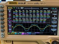
Amp .jpg


It seems quite stable when looking at gain/phase margins. However, when I feed it a square pulse, the result is this:


Square wave.jpg


I don't really know how to interpret this, is it bad? if so, what could be done about it?

Looking forward to your comments, also in general about this circuit.

Attachments

Designing and building external speakers for 8002D Bluetooth speaker unit

My experiments with speakers and amplifiers located in the subterranean layer of the Hi - Fi world continues. Subterranean in terms of cost.

Here is my latest project, which is proceeding nicely: When the TEA 2025 amplifier stopped working properly, I hit upon the idea of connecting an inexpensive speakers to my existing Whafedale Diamond IV speakers. The results were surprising, while bass was totally lacking, it could be boosted using the music player (Musicolet) equalizer for acceptable levels of musical enjoyment.

I am in the process of building a set of speakers specifically for this little Bluetooth amplifier, with some success. I am getting 70 dB at 1 metre with these connected to large vintage floor standers of 89 dB sensitivity.

I had a few questions though.

Resistor inline vs series notch for tweeter. Sound quality and protection?

Hi,

Tried idea on VituixCAD to use series notch filter on tweeter for pretty high frequency ~11.5-12.5kHz, Q of ~0.8 to ~1.4. All the frequencies and Q between kinda work and give good results on perceived sound quality, graphs are better too. With that notch filter I can get away only with capacitors in the path between tweeter and amp, no resistors are needed, no additional L-pad. Sensitivity looks more or less the same with "side" filter vs inline resistor. Graphs differ, but nothing out of the ordinary.

Tweeter is dome fabric, 25mm, crossover freq is ~2.4kHz, tweeter Fs is 1500Hz, 8Ohm. The setup that interests me is 3rd order + notch explained above,

In the animated gif there are 3 examples:
"R1" 3rd order and resistor in front - 1 side bypass route
"R2" 4th order and resistor in front - 2 side bypass routes
"R5" 3rd order and series notch after - 2 side bypass routes

The questions are:
1. What is the extra purpose of resistor in line with tweeter except for reducing the sensitivity: General improved sound quality - can it be measured or/and heard? Filtering of some unwanted hissing? Some protection vs amp clipping or some artefacts coming from source such as accidentally disconnected wire, power loss and so on?
2. If it is recommended to do this - can I get away with some "dummy" of 0.1-0.5 Ohm or more is needed?

All 3 variants attached, but the first two are just similar xover, with 3rd or 4th order crossover.

Attachments

  • 2025-02-05 16-32-46.gif
    2025-02-05 16-32-46.gif
    816.9 KB · Views: 108

Why the dip at ~550Hz (nearfield)

This is my first attempt at speaker design from scratch (repurposing old BOSE acoustimass drivers). Bringing them together in a TMT arrangement with the satellite FR drivers. Attached is the box design. Attached also are some 1'/15ms gated measurements using a umm-6. Before and after felting the inside (Felt from a vintage westinghouse cabinet). I am seeing some sort of interference at just about 550Hz that the felting did not take care of.

What sort of obvious thing am i missing? (other than that these drivers are way outside of their intended usage?

Attachments

  • Screenshot 2025-02-02 at 6.59.55 AM.png
    Screenshot 2025-02-02 at 6.59.55 AM.png
    4.8 MB · Views: 498
  • Screenshot 2025-02-02 at 1.08.51 PM.png
    Screenshot 2025-02-02 at 1.08.51 PM.png
    291.4 KB · Views: 118

FS:Yes It Can Drive an F4 (fully built and full kit)

Too many builds and too little time! I have for sale one of MJ’s “Yes It Can Drive an F4” full kits (which is enough to build 2 channels) as organized by our wonderful colleague birdbox as well as two fully built/populated and tested boards. They work wonderfully. For the kits, I have taken the time to provide matched N channel pairs for the differential input stage saving you time.

Each board is for a single channel.

$OLD including shipping in USA for the kit. The kit contains 1 white board and 1 red board and all parts including the appropriate matched transistors.

$OLD including shipping in the USA for the fully built/tested boards, ready to plug and play. Each board has been cleansed of all flux residue.

Paypal preferred.

Best,
Anand.

Attachments

  • IMG_0987.jpeg
    IMG_0987.jpeg
    881.3 KB · Views: 122
  • IMG_0988.jpeg
    IMG_0988.jpeg
    963 KB · Views: 128
  • IMG_0989.jpeg
    IMG_0989.jpeg
    783 KB · Views: 124

Jmlab SW-33A repair

Hi all!

Searched for some time, hope this is no dupe!

Got this Jmlab sw-33a (12" focal sw) that needs alot of love!
One transistor blown (visualy), 1 15000uf cap vented and possibly more!

I have not been able to find any schematic or specs on sw element such as impedence, it measuers 6.7ohms and is a real pain to drive as my only amp around tripps when i raise vol, so i wounder is it really this heavy to drive, or is it busted? it is a impressive peice of element, so would not be supprised if it is heavy to drive.

The amp has been tempered with, previous owner probably done a cooling paste replacement and overlooked the plastic washers between heatsink and transistors causing a shortout trough the heatsink, leaving one transistor visualy blown and vented one of the big caps (elna lp5 15000uf/63v).

Starting out like this, pictures of the thing will popup as i work with it.

Denon AVR-5800

I have a Denon AVR-5800 that stopped working several years ago. I took it to a Denon authorized service center who said a digital board went bad and that since the board was no longer made by Denon they could not repair it. For a while I had in my mind the thought of using the preamp inputs and bypassing other components inside to make it into an amplifier. I even posted here about it and got some useful advice: https://www.diyaudio.com/community/threads/using-amp-in-receiver.342695/

Unfortunately I never got around to it so it has been sitting in its box for several years.

As far as I know all the amplifier components are fine. The thing is a beast. It weighs about 50 pounds, was rated as 170 watts/channel, and has a massive toroidal transformer. It seems like a terrible waste to send it to the recycle bin and I am hoping someone here could use it. I can see someone using the transformer in an amp they are building or using both the transformer and amplifier boards to make an amp. Somebody with the right skills might even be able to repair the digital board that failed.

So, I'd like to sell it to someone for any reasonable offer. I am located in the Houston area and it is probably too heavy to ship economically so it needs to be someone local. Does anyone want it or have any ideas of what I can do other than recycle it?

hot solenoids on Teac A-4010s.

I just purchased a Teac A-4010s that was made in 1970. I am in the prosses of going through it and doing what I can to fix some of the issues it has. I am not an experienced tech but I can do simple work. It seems that the two solenoids are running hot. I don't know what too hot is for these units but the front panel get hot to the touch. I can get to the leads on the one and measured 83 vdc across it. I can't find anywhere that list what that voltage should be. I appreciate any help I can get.

For Sale TDA1540 DAC full set

Selling all parts to build a high end TDA1540 DAC, selling due to having too much projects going on!
All boards have been tested and DAC is confirmed working, you just have to wire everything up and build it into the case!
Set contains:

Miro TDA1540 DAC board: PSU decoupling caps changed to Elna Silmic II, opamp sockets have not been populated.
Altera CPLD I2s converter: converts I2s to offset binary, flashed with Miro's firmware and including USB blaster
SPDIF/Toslink receiver board, with Cirrus Logic WM8805 receiver chip
2x CEN FC IV boards: great IV converters, with matched FETs, Audio Note Kaisei capacitors and Rhopoint IV resistors, tested and DC offset in the 0+-3mv region
5x Salas UltraBIB shunt regulator supplies: 3x pos and 2x neg
2x SilentSwitcher 2024 model: -15 0 +15V supplies
2x R-core transformers: with all the necessary taps, including 115V and 230V primaries
1x Hifi2000 3U case, with 10mm thick front panel: new and unused including IEC socket and illuminated power switch

Will add 2x TDA1540 additional DAC chips and unpopulated CEN filter boards

This needs to go to a good home, so asking 500€ for everything, will ship worldwide

Ask if you need some different digital input options, have some XMOS USB boards or Rpi with FifopPi Q7

Attachments

  • tempImageC7fto9.gif
    tempImageC7fto9.gif
    1.2 MB · Views: 188
  • tempImagec1sOUT.gif
    tempImagec1sOUT.gif
    1.2 MB · Views: 172
  • tempImageVjvOdF.gif
    tempImageVjvOdF.gif
    1.8 MB · Views: 179
  • tempImageYWTJVh.gif
    tempImageYWTJVh.gif
    1.4 MB · Views: 1,849
  • tempImagexcodHQ.gif
    tempImagexcodHQ.gif
    1.6 MB · Views: 987
  • tempImageUIMVOl.gif
    tempImageUIMVOl.gif
    1.5 MB · Views: 580
  • tempImageb3hsbD.gif
    tempImageb3hsbD.gif
    1.6 MB · Views: 1,025
  • tempImageQ7j3qA.gif
    tempImageQ7j3qA.gif
    1.8 MB · Views: 871
  • tempImageAVRNgv.gif
    tempImageAVRNgv.gif
    1.5 MB · Views: 999
  • tempImageKB9W4R.gif
    tempImageKB9W4R.gif
    1.4 MB · Views: 476
  • tempImageIBmG8W.gif
    tempImageIBmG8W.gif
    1.4 MB · Views: 1,113
  • tempImageRzCiLS.gif
    tempImageRzCiLS.gif
    1.5 MB · Views: 339
  • tempImageeGMdDa.gif
    tempImageeGMdDa.gif
    1.6 MB · Views: 826

BF862 based SE Class A Headamp without the HEAT

I was looking for a small portable amp for my DT880-250 headphones. I wanted class A and I wanted longer battery life and low rejected heat. These sound like requirements that are at odds with each other right?

This project started in another thread and is based on the BF862 JFET single ended White follower design suggested by EUVL here. The design has a fairly low bias current of about 50mA, but because it used qnty 8 x BF862 JFETs on the output stage in a singel-ended arrangement with about 12mA in each device, the overall heat dissipation is very low but it is guaranteed to work in pure class A (it has to because of the topology). This amp is very simple to make following this schematic:

581624d1479910835-tin-fets-headphone-amplifier-many_many_jfets.png


I did my layout using a drawing program (MS PowerPoint in this case) and came up with this:

586034d1481838813-bf862-preamp-bf862-ha-layout.png


I then made iron on transfers using laser printer and got this on the copper as the etch mask:

586104d1481882105-bf862-preamp-bf862-ha-build-03.png


Etched in HCl and peroxide (hardware store muriatic acid concrete sidewalk cleaner and hydrogen peroxide (3%) for 20 minutes:

586105d1481882105-bf862-preamp-bf862-ha-build-04.png


Etched board looks like this:

586106d1481882105-bf862-preamp-bf862-ha-build-06.png


Soldered it up (I had to switch 1R source resistors for 33R to keep my bias current low, it was pegged at 23mA ea wit 1R):

586284d1481965252-mosfet-follower-headphone-amplifier-bf862-ha-build-stereo-08.jpg


I had some difficulty getting it to make sound at first and found out that the problem was a bad 6in length of wire from the output terminal to the headphone jack. Took hours to figure that one out after debugging the board components.

Initial tests were done at 12v supply and I boosted that up to 17v to get a little more headroom and keep heat down still. I am using a small DC to DC boost converter (400kHz switcher) and added 2200uF cap to filter it some more. Ripple is about 9mV at 17v but luckily the amp has some decent PSRR and output measures 0.3mV with inputs shorted. It is silent to my ears anyhow. Absolutely no hum or hiss. Cannot tell it is on.

I spend half a day listening and decided it was worthy to be boxed. So using this niftly enclosure. After drilling some holes and adding a 50k stereo pot, and power jack, switch, LED indicator, 3.5mm jacks IN and OUT, the amp is completed:

586398d1482011463-bf862-based-se-class-headamp-without-heat-bf862-ha-build-boxed-10g.jpg


Here is the (messy) inside. I am not one to have neat wiring harnesses as my time is very limited to work on it. The wires work fine and do not seem to pickup noises. All wires are at least twisted:

586399d1482011463-bf862-based-se-class-headamp-without-heat-bf862-ha-build-boxed-internal-11.jpg


Edit: I added a cap multiplier using IRF540 MOSFET with 10mF output ca[ and circuit from Juma's Easy Peasy Cap Mx thread:

586803d1482215824-bf862-based-se-class-headamp-without-heat-bf862-ha-build-boxed-internal-cap-mx-12.jpg


Here is the amp next to DT880's that I will be using them with. I am using a 2200uF 16v electrolytic cap for C2 bypassed with 1uF 230v MKT. I initially used 330uF OSCON but found the bass lacking. With the 2200uF I can hear deep deep bass now. There is a 270R 2W load resistor, so when I plug in the 250R DT880's, overall impedance is about 125R - which I think may help to draw more current out of the amp so it gets more impact with the bass (seems so subjectively).

586400d1482011463-bf862-based-se-class-headamp-without-heat-bf862-ha-build-final-dt880-12.jpg


So in addition to sounding extremely detailed, neutral, and having excellent bass authority, they are absolutely cool. The case is ambient temperature after hours of playing. Also, since I am using a XL6009 switch mode step up regulator, the power supply input is very flexible. For desktop use I have a 12v 3A SMPS wall wart from my external disk drive. For portable use, I will use a 5v USB phone charger battery pack and let the step up take care of getting the 17v rail. I estimate a 10,000mA Li-ion battery pack will last more than 12 hours. That's a lot of pure class A play time for a small battery.

This amp sounds wonderful and I thank EUVL for a great design. It has indeed been tested and works very well. Give it a shot.

Edit: Dec. 22, 2016 - an attempt at a smaller 37mm x 26mm layout to fit in an Altoids tin with two 9v batteries.

587101d1482351920-bf862-based-se-class-headamp-without-heat-bf862-ha-small-v2.png


Edit: Jan 6, 2017 - portable battery operation using 5v USB charging battery pack. 10,000mAhr cell should last about 15 hrs.

590340d1483735403-bf862-based-se-class-headamp-without-heat-bf862-se-ha-portable-demo-v2.jpg


Sound is still great - using XL6009 DC to DC step up internally for 18v supply to amp (after cap Mx).

Edit: Jan 7, 2017 - Here is a new portable 2 FET design that sounds great - very easy to make. We will have a GB soon so stay tuned!

Schematic and THD prediction:
591187d1483977924-bf862-based-se-class-headamp-without-heat-pocket-class-bf862-zvn5306-ha-v1.png


FFT HD profile (sweet H2 and not much else!):
591189d1483977924-bf862-based-se-class-headamp-without-heat-pocket-class-bf862-zvn5306-ha-v1-fft-1khz.png


Implementation as portable mint tin pocket Class A amp a la CMOY:
591117d1483961316-mosfet-source-follower-headamp-pocket-bf862-zvn4306-ha-smt-tin-case-dtr880.jpg


Internals of above amp:
591116d1483961316-mosfet-source-follower-headamp-pocket-bf862-zvn4306-ha-smt-tin-case.jpg


590981d1483910917-bf862-based-se-class-headamp-without-heat-pocket-bf862-zvn4306-ha-top-side.-caps-mods.jpg


590982d1483910917-bf862-based-se-class-headamp-without-heat-pocket-bf862-zvn4306-ha-smt-side-mods.jpg

Attachments

  • BF862-HA-build-boxed-10g.jpg
    BF862-HA-build-boxed-10g.jpg
    67.9 KB · Views: 8,765
  • BF862-HA-build-boxed-internal-11.jpg
    BF862-HA-build-boxed-internal-11.jpg
    140 KB · Views: 8,725
  • BF862-HA-build-final-with-dt880-12.jpg
    BF862-HA-build-final-with-dt880-12.jpg
    109.6 KB · Views: 14,278

Help on single ended 211 question

A very impulsive question 🙂from a layman.

I have a 211 single ended amplifier with a very simple transformer coupled signal circuit as attached that I am rebuilding with replacement capacitors, as it's 30 years old etc.

I also have a small valve output DAC and I have just found a fabulous sounding valve: Sylvania GB5670 that I am using in the DAC output stage.

The thought occurred to me that I might replace the 6c45 driver valve with a 5670 running both triodes in parallel instead (1 per channel). I can easily change the Plate voltage as it comes from a 500V supply taken down with a 10K series resistor.

Is this a crazy silly idea for a 211 driver valve or is it something to genuinely think about?

Appreciate your input/thoughts

Thanks!

Rich

Attachments

  • Screenshot 2025-02-05 at 19.05.04.png
    Screenshot 2025-02-05 at 19.05.04.png
    3 MB · Views: 399

Masonry casting artist; Suggestions for full range driver

I love doing sculptural art and have made a lot of other stuff but Im up to a floor standing speaker
I would like to use a full range decent driver.
Im a fan of punchy sealed bass and cabinet can be up to about 50l
I have heard a lot of PR enclosures that have actually sounded quite good but I dont have the same design limitation as box builders ...its just the group delay can be a bit disconcerting for bottom end.

Am wanting to only have a single driver visible and any bass porting/manifolds/pr will be constructed internally and vent as a downfiring output but the PR or whatever can be vertically mounted into a manifold as well

Considering these parameters; are there any recommendations. I mentioned PR because I saw Hexibase get pretty decent sub out of small drivers that was quite impressive

I have quite a number of ideas but will prob start off with this which is a stylized tusk and stands about 1.5m high to be a balance with the driver receiver being about 200mm
I use a proprietary sustainable masonry material called wood stone(TM) which can easily stop a 50 cal @200mm thick so its a very energy absorbing material and is quite tensile. About 0.6 the weight of concrete.
1738808500560.png


Ive done translation monitors which were at NAMM (all hand made so Im only a boutique artist kind of guy) so this gives an idea of the material applied
Login to view embedded media
Any help would be amazing

For Sale X-Altra MC/MM Phono EQ Amplifier

I built 2 of these, but my plans changed and they are no longer needed.

$250 USD Each

Attachments

  • IMG_1308.JPG
    IMG_1308.JPG
    318.9 KB · Views: 324
  • IMG_1309.JPG
    IMG_1309.JPG
    333.8 KB · Views: 330
  • PXL_20230414_205601794.jpg
    PXL_20230414_205601794.jpg
    398 KB · Views: 314
  • PXL_20230417_184021073.jpg
    PXL_20230417_184021073.jpg
    267.4 KB · Views: 318
  • PXL_20230417_184041651.jpg
    PXL_20230417_184041651.jpg
    389 KB · Views: 321

FS: Iron Pre Balanced kit (2023)

Hi folks! Great partial kit, but unfortunately, I don’t have much time for all my diy building endeavors.

This is the balanced version of the 2023 Iron Pre kit including the JFET transistors. The kit is unbuilt and only opened for inspection. Brand new.

Pics below:

IMG_0993.jpeg


I’ll need to revisit this design in the future most definitely. But for now, I’m going to let it go!

$OLD! inclusive of shipping in the USA. PayPal preferred.

Best,
Anand.

Attachments

  • IMG_0995.jpeg
    IMG_0995.jpeg
    324.3 KB · Views: 54
  • IMG_0994.jpeg
    IMG_0994.jpeg
    1.1 MB · Views: 59

New here from Georgia, USA

Hello everyone!

I have been building amps (guitar and hifi - both tube and solid state), preamps, guitar pedals, midi controllers, and etc. for many years. Mostly not from kits, but some of those too. Have designed some of my own stuff but have only built a couple of things from those designs (primarily unique compression and EQ control). I also build guitars, DMX light controllers, and nearly anything related to music except speakers (although have built cabinets).

Started looking into DIY DSP effects/devices, but honestly am intimidated. ;-) I can program in C++ for Arduino just fine but seems like a whole other level with DSP stuff!

Would love to learn about adaptive EQ, DIY modeling amps/pre-amps (from scratch, not kits) and other more complex audio devices.

Glad I found this place!

P88 preamplifier - moving volume pot

Hello,

For anyone that is familiar with Rod Eliott's P88 preamplifier, I have a question. Is there a problem if I move the volume pot from between the stages to the input directly. I do this because I want to recreate the tone + loudness circuit of a vintage Sony preamp that I love, and that uses a passive Tone module at the input signal. Would there be any disadvantage to moving the volume pot to the input. Thanks !

Ideas for a Two-Way Bookshelf Speaker Build Using Dynaudio Chassis

Hello, I’d like to start my first DIY speaker project. I have two Dynaudio D28AF (8 Ohm) and two Dynaudio 17W75XL (4 Ohm) drivers and would like to design and build a bookshelf speaker with them. It would be great if someone could share ideas for the enclosure and crossover, or perhaps point me to a Dynaudio design plan for these drivers and provide the schematics.

Attachments

MEH 2-way - Tuned rear wave port feasibility?

Has anyone been able to get a tuned port to work with success in a 2way MEH? I know danley uses them on his 3 way units, but then at the same time Iv been seeing folks on this forum not to happy with ports performance in their designs.

To be clear im not talking about the entry ports for the drivers but using the back phase of the speaker like a a hemholtz resonator to get extra low end, but with without the tube.

Seems like a waste to not use that energy.

What am I missing?

The VeraFi Audio A40 Amp

I have been talking a little bit about this amp on the What’s On the Bench Tonight thread, but thought it’s time to give it its own proper thread. It started as a 25W Class A amp, and now has progressed to 40W - mandatory Class A operation since the topology is SE Class A with a an active push-pull CCS based on the Aksa Lender P-Chan Complementary Aleph (ALPHA Nirvana) output stage developed by Hugh Dean and used here under license to Aspen Amplifiers PLC, Melbourne. The layout is by JPS64 which means this is a state of the art amp in terms of layout symmetry, low impedance traces, thousands of sticking vias, and careful attention to minimizing ground loops and noise immunity.

Some of the notable features that this amp will have includes:
  • Dual Monoblock design with independent power transformers and amp boards
  • Solid State Relays (SSR) for speaker DC protection similar to the RTR SSR designed by jhofland
  • SSR Soft Start with soft mains On/Standby button in front panel similar to the SFP designed by jhofland
  • Custom All-CNC milled and satin bead blasted hard anodized aluminum chassis with thick 5mm walls and massive 40mm heatsink plates. The chassis is a massive amount of aluminum on the order of 25 to 27lbs. Chassis look, shape, HMI and layout is all my own design and the 3D modeling and CAD is by Darko M.
  • Dual analog meters for output power with backlight
  • Premium Viborg copper binding posts
  • Premium gold plated RCA jacks
  • Front panel Mute switch via SSR enable
  • Automatic over temperature safety shutdown with dual thermostatic switches that activate the SSR
  • Maximum output power of 40W into 8ohms and the wonderful ALPHA Nirvana 2nd harmonic dominant distortion profile with relatively low THD of circa 0.005% THD at 2.83Vrms into 8ohms
  • Beautiful classic lines for an enduring timeless visual look
This will be offered through my XSA Labs website and we plan to offer a limited run of 25 first production units at an introductory price of $1599.

29E3D291-2737-469B-AA06-EC14F0972476.jpeg

0EEE1973-9BF0-4A8A-9BAA-77090BC39976.jpeg


We are exploring anodizing color options for the handles and heatsinks. All black is still a major contender.

11119D56-D7E2-421D-9807-DB6E0BB47A7A.jpeg


The internals will be laid out like this with the amp and its PSU mounted together on each heatsink. The floor of the amp will house the dual toroidal power trafos and also a main board let’s the SSR’s for the soft start, the main IEC soft On/Standby, and speaker SSR’s.
1674854997251.jpeg


Here is a closeup of one channel of the amp and on-board CRC PSU on one PCB assembly. You can see the temperature sensor on the heatsink. Keantoken helped with the construction and assembly of the amp PCBA.
1674855213537.jpeg


Initial testing of this amp indicates it sounds superb and the latest work is expand the chassis an extra 50mm deep to reduce heatsink temperatures and permit full 50W operation.

You can listen to it here:

Vanguard speakers
Login to view embedded media
XSD speakers
Login to view embedded media

Ibanez TSA15 head retubing and setting the correct bias

Dear Forum,

I have been asked to retube an Ibanez TSA15H tube head amp. Could someone help me how is it done correctly? I received the amp with a set of replacement tubes (2x 6V6 S and 2x ECC83 S)
I've read somewhere that it has fixed bias, so maybe nothing could be done except replacing the tubes.

Thank you for your help in advance!

How stable should DC anode voltages really be?

Hi,

I test my anode voltages with a DMM set to DC and I see the voltage 'swing' from in my case 183v to 179 or so over maybe 10s or so on a slow fluctuation back and forth. Should this be like this or could it be indicative of a more fundamental fault. Other voltages in the amp don't move like this really.

Sorry if this is a dumb question?

Thanks,

A Digitally Programmable Graphic Eq

I've always wanted to make digitally programmable tube preamp like the Mesa Triaxis. As I gear up to do the high voltage parts of that project I decided to start at the back end and make a 5 band graphic eq that was programmable. The Triaxis cuts some corners and prewires the EQ to a popular curve, then the "dynamic voice" control sets the amount that is applied - I want a real 5 band.

Since the EQ is at line level I'm using AD5293 digital potentiometers. It's mostly surface mount and small parts so a it's little scary if you haven't done it before. Fortunately I've been slowly moving all my projects to more SMD and, frankly, I like it a bit better in some regards. The board works (mostly*) but I haven't set up a good control scheme so the pot shown below is either adjusting one band or the whole "voice" depending on what parts of the code I activate. Most importantly it's pretty transparent and when set "flat" it sounds the same as my normal guitar tone. This proof of concept opens the door to digitally controllable tone stacks and maybe even front-end drive circuits if the gain doesn't cause digital noise to leak in.

* "mostly" because I implemented the zero cross circuit in the data sheet for the AD5293; one of the components in the sub circuit was damaged by heat I think and was clamping the 5v rail to .9v. So I had to rip out the sub circuit and bypass it. Perhaps you can see the 30awg jumper wire. Regardless, the popping from updates to the pots is only noticeable in some circumstances but I'm going to replace the bits and see if I can get it working.

IMG_4223.jpeg
IMG_4222.jpeg

FM 155 module 19202

Sono interessato ad acquistare un modulo 19202 per il mio preamplificatore FM Acoustics 155.
Per favore dimmi dove posso comprarlo?
Il modulo crackato andrebbe bene, ma non so dove trovarlo. Grazie.

:cop: Moderator edit.

I am interested in purchasing a 19202 module for my Acoustics 155 FM preamp.
Please tell me where I can buy it?
The cracked form would be fine, but I don't know where to find it. Thank you.

UNgo

DIY Speakon cable

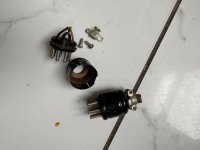
First time trying to do this.

There are 2 and 4 pole Speakon connectors (even 8).

I will use this cable for my home audio. No bi-amping or bi-wiring. I read that 4 pole is for bi-amping. Does it also mean for bi-wiring?

Would not be future proof to get the 4 pole if in the future I want to bi-wire (not-bi amp) if I get bi-wireable speakers?

Will be using a pro amplifier hence the desire to build a speakon cable.

Art installation sound

Hi,

I have a sound installation where I will put 24 speakers in a sculpture.
I have a question that might be very simple to all of you regarding power.. a help would be kind as it's not my field.

I will use some Dayton exciters 8ohm / 25W with an amp that is 2x50W @4ohm powered with 18V.
I did a test with 2 speakers and it works well.
But I need 10 speakers so I will use 5 of those little amps.

I will use also 6 x 3W/4ohm speakers with small 2x3W amps that are powered by 5V.
so that's 5 18V powerblacks and 3 5v powerblocks.
I thought I could reduce that and power things in serie.. I asked chat gpt and it said I need for the 18v amps a 40Amp powerblock 😛

First that scared me a little bit thinking it's a lot. But also there's no powerblock doing this.
So how do I calculate the current I need ? because the amp info only says "wide working voltage range of DC4.5-26 V."
I would say for one amp the process is this ? :
2x50 = 100W
P=UI
so I = 100/18 = 5.5A ?
is that right ? I feel 5.5A looks high but what do I know ?

thanks for your advice,
Cheers,
Sylvain

Zenductor

Hi

Is it possible to find out a little more about the Zenductor before the upcoming Burning Amp ?

Thanks
Eric

Zenductor


````````````````````````````````````````````````````````
(EDIT) @6L6 here, Eric has allowed me to put some links and such in this top post to make things easier to find. Thank you!!


Here is the post with Nelson's article - ZENDUCTOR ARTICLE


zenductor.jpg


zenductor-jpg.1215963

Beautiful pair of amps built by Mike Rothatcher sitting on the optional chassis pans.

Hi I'm Stew, not an electronics expert, but a good all rounder. Looking forward to being part of this group

I am in my 50's and have been a bookbinder for just over 10 years and I love it, I spent 20 years prior to this as an electro mechanical engineer working for Eastman Kodak based in the UK, servicing and repairing main lab and high street photo-lab equipment. I ended up becoming training manager for EAMER and travelled extensively throughout Europe and Africa. I have always loved Hifi and brought my first system at 18, NAD 3130, Mission 737R's and a Dual MkII turntable from Sevenoaks Hifi, I loved them and still have all but the Dual, although both the NAD and the Missions are both broken, which is part of my reason for being here. My current system is a recently purchased CA A60, Thorens TD166 MKV a Pioneer PD-S703 stable platter CD player (built in DAC perfect for the A60) and a pair of Ditton 130's. I also play guitar, a Yamaha CJ12 acoustic and a Gretsch Corvette, I have a WEM 30AMP Dominator, also broken, which I would love to repair. I am looking forward to meeting like minded people, making new friends and fixing all my stuff!

Request b-con go Android software

Dear forum friends, I have encountered a problem. I am currently using AUDISON's B-CON Bluetooth and my phone is on Android. I want to download the B-CON GO software, but I can't download it. I can't connect to Google Play. Because Google Play is not available in our country. Could you please help me upload a B-CON GO apk software from overseas. The download address is https://audison.com/b-con-go/ Click on the Android version to download, thank you.
微信截图_20250110151415.jpg

replacing a 60Hz motor with a 50Hz in a Clearaudio Emotion/Marantz TTS15-1

I'm the owner of a Marantz TTS15-1/Clearaudio Emotion turntable that I bought in the US and I moved to Italy. Basically after trying to save money by buying a step-down transformer and a pulley which ended being the same as the one I had from the US (by the way only the MarantzTTS15-1 for the Japan market have a 60 and 50hz pulley, EU and North America both share the same pulley) I realized that I needed to change the motor (synchronous AC motor) and that Clearaudio wants to rip me of of 400-500 euros...

Is it as simple as opening my current motor and finding an equivalent Premotec 50hz motor, ordering it and installing it? Do I need to do some soldering. Have no experience but willing to learn as it could be a fun projet. Not sure where to start and any help would be greatly appreciated! Thanks

Looking for Moode 7 (64-bit) Image for Testing

Hello DIYAudio community!

I’ve been using Moode Audio for a long time and have experimented with many versions, but Moode 7 has always been my favorite. Unfortunately, my microSD card got corrupted, and I lost the image of this version.

Why Moode 7?

I have a tube-based setup with a Line Magnetic LM-216AI amplifier, Magnat Signature 1105 speakers, and Pi2AES HAT. Over the years, I’ve tested various combinations of NOS tubes, DACs, and SD cards—each of them influencing the sound in my system. I remember that back when I was using Moode 7, the sound was deeper, more immersive, and had better soundstage.

Now, with the newer versions (8 and 9), I’ve noticed changes in tonality. Moode 9, in particular, sounds brighter and less spacious in my setup. I suspect this could be due to different memory handling or kernel optimizations, but I haven't found a way to tweak it yet.

Does Anyone Have a Copy?

I’m looking for a 64-bit Moode 7 image for testing. If someone still has it stored or knows where I can find it, I would greatly appreciate it!

Thanks in advance for any help! I’d also be happy to share my experience with different SD cards and their impact on sound quality, as I’ve done some extensive testing in this area.

Best regards

Combining Capacitors In Parallel

Please excuse such a basic question. I want to only order parts once, so wanted to post this up.
I have read info on the internet that states two capacitors can be connected in parallel and the the ratings will be additive (assuming they are the same voltage rating). However, the examples I've seen are always two caps of the same rating (i.e. 25 ohm uF+ 25 ohm uF = 50 ohm uF).

My question: Does this also apply when the caps are different ratings (i.e. 10 ohm uF + 22 ohm uF= 32 ohm uF)?

305Vdc HV regulator adjustable via zener diode too slow 7seconds

I try simulate 305VDC HV regulate supply adjust by change value of Zener diodes normally 75V zener. To use with 6sn7 and 45 total load is about 86mA

the problem is it take almost 7 seconds to get 305VDC.

How to solve problem?

if anyone can help provide 305vdc HV reg, will be much appreciate

thx

Attachments

  • 72AF0DC0-C2CB-40BB-84CC-38B3C34F009A.jpeg
    72AF0DC0-C2CB-40BB-84CC-38B3C34F009A.jpeg
    113.3 KB · Views: 360

New member, 50-year Audio geek I'm interested in building speakers

Hello, I have newly joined here, I am a 60-year audio/speaker geek, since my dad first showed me his Hi-Fi tube mono amp, homebuilt speaker cabinet with a Magnavox "full range" speaker, and then his Hallicrafters SW radio.

By 16 years old, I was hooked, built his next stereo speakers (Peerless) at age 18, later my first speaker high end build during college at LSU, in the mid 1980's with Dynaudio components with Butterworth crossovers from Madisound.
Built (just completed assembly) of a Hafler Pre Amp and 150 W power amp.

Recently, my passion for quality audio has been rekindled.

Looking for open source power supply design with remote trigger input

Does anyone know where I can find a DIY power supply with remote trigger input(s)?
I need a PSU for my subwoofer. I want it to be triggered on when I switch-on a TV, an android tv-box, amplituner or a satellite receiver. That is at least four trigger sources.
It would be best if it had different trigger inputs like HDMI, USB, 5V jack, 12V jack, audio signal sense, etc...
It can be just the control board with trigger inputs and a mains relay output, but it can also be a complete power supply: the trigger board and a high power supply board with soft start etc...

McIntosh c-26 preamp vs. c-28

Currently, I’m using a c-28 preamp with my MC-7270 power amp. I saw a c-26 preamp in Missouri for sale, and this one underwent a pro restoration last month. I’m really interested in purchasing the c-26 to have as a backup, because I’m sending my c-28 out to be pro restored. I’m also curious to know which of these two is most preferred by Mac purists when it comes to sound and build quality. Please let me know

Is dynakitparts still shipping product

I am thinking on building a classic 6BQ5 amplifier just for fun.

While looking for a Dynaco ST-35 kit or perhaps a transformer set I noticed that dynakitparts is out of stock on both.
Looking at the dynakitparts WEB site they seem out of stock on basically everything.
This is a pity.
Does anyone know if there is a path for them to recover and offer product to ship again?

Or perhaps you can suggest a another vendor that can supply a true copy of the ST-35 output and power transformers?

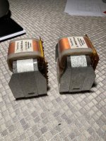
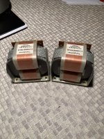
Output transformers from China: understanding the market

Hi there.
Been exploring the Chinese market of tube output transformers to look for SET ‘formers 3.5k primary. Difficult to get through:
  • aliexpress search function is innefective with keywords (is there a trick to retrieve only pertinent results and not everything but what one is looking for?)
  • there appear to be no real brands and references other than those attributed by vendors (has anyone identified brands and model numbers that can be searched for?)
  • a given model gives rise to various electrical characteristics even on the basics (weight, dimensions). Electrical characteristics are seldom realistic (eg 10hz-39khz @ -0,6dB for a 1,6kg ‘former)
  • other culture with OTs: small transformers are privileged often with figures similar to those of reputable models from Japan etc.
Projects by fanatics, for fanatics
Get answers and advice for everyone wanting to learn the art of audio.
Join the Community
507,663
Members
7,883,171
Messages

Filter

Forum Statistics

Threads
405,981
Messages
7,883,171
Members
507,663
Latest member
The driver