Exponential horn. Flattened cut sheet.

If you have the measurements for a horn, how do you calculate distance between each segment when the horn is “unrolled” onto a flat sheet. In the constructed horn the length between each section will be the same, but when the pieces are flat, the length will get longer as it gets closer to the mouth.

I am building an altec 1505 out of 1/8” plywood, if that is relevant!

Attachments

  • 9115BACD-8C31-4D88-8106-245E7469E7CA.jpg
    9115BACD-8C31-4D88-8106-245E7469E7CA.jpg
    371.9 KB · Views: 121

LM1875 non funziona

LM1875

Hello everyone, I'm new to the forum and I wanted to ask you for a courtesy given your experience,
could you give me a correct schematic for an amplifier with lm1875,
I'm not very experienced, but I'm trying to make one.
I followed some pattern found on the net and they don't seem to work.
I tried to find some in the forum but I couldn't.
every time I assemble one I have a problem lately
the volume was faint, in another loud noise from the speakers.
I just can't understand where I'm wrong, but I would like to start at least from a fixed point, that is a working and well tested scheme.

thank you for your kindness.
See you soon

ps this is the last pattern I followed

Tales From the Chip: LM1875 Audio Amplifier : 8 Steps (with Pictures) - Instructables...
?

Help troubleshoot tube PSU ... blowing fuse

I made a PCB to hold 2 diodes, a cap and a bleeder resistor for use with a center-tapped transformer.

Upon initial test, fuses are blown.
Increasing the fuse size causes a momentary buzz from the transformer and then blown too.

If I disconnect the transformer leads from the PCB, the transformer is outputting 600 VCT so it seems to be fine.
It seems like there is an obvious mistake here that I'm overlooking.

The 600VCT wire leads are connected to pin 1 and 3 on the input, and the center-tap lead is connected to 0V output.

The parts I used were:
2x MUR460 diodes
150K 2W bleeder resistor
220uF 450V snap-in capacitor.

Thoughts?

Attachments

  • Capture.PNG
    Capture.PNG
    41.2 KB · Views: 133

PPI A600

Im working on a PPI Art A600 which had failed outputs on the left channel. I replaced all outputs in BOTH channels with 2n6488 and 2n6491 as the originals were BDT81/BDT82 and NLA. There is 1 twist as there is an extra 91 on one channel, and an extra 88 in the other channel. I believe I did this correctly as I went over it 3 times before soldering. I did not replace any drivers which are C2344 and A1011 being controlled by MPSA06. All these transistors are testing out well off the PCB.

The amp powers, and gently plays through speaker terminals to my HoneyTone, but as soon as I hook up an actual 4-ohm load the amp clamps on my power supply and there is no sound.

Another symptom is the amp can only be powered for about 40 seconds before the outputs get too warm for idling. Also amperage draw starts at 1.3A, and over that 40 seconds rises to un-expected levels. I pulled power at 2.75A as it was starting to really take off.

All VR pots are set to full CCW. There is no voltage across several emitters I've tested.

The left channel has 1.4vDC on it while the right has +-0.1vDC. Theres a DC reference pot but it can only get the left channel down to about 1.1vDC.

Am I missing something? I checked multiple components and nothing is popping out at me.

Meridian 557

Hi all,
I really appreciate any of you who can help me find schematic diagram of my OLD Girl who stop working just recently MERIDIAN 557 Power amplifier, this old girl serve me very well for the last 10years, lots of parts are toasted, especially in HVtransistors, so please if anyone of you have come across or may have repaired same issues that I have please share it with me thank you all folks

Hello from South Dakota! / Rockford Fosgate 600a4 Problem

Hello all, Just joined this site. Seems pretty legit at first glance. Surprised I haven't seen it sooner than now. Anyway, looking for anybody that can help with some repair questions on a Rockford Fosgate 600a4 mobile audio amplifier. When I purchased this amplifier ($20) I did not do any inspection of the unit and was unable to test. Oh well,m I'm the guy that enjoys the vhallenge of fixing things!!! In the event that it didn't work. Well, it worked great! But....,you knew this was coming, the gains were so terribly gouged out that they were hardly recognizable as potentiometers. I tried soldering in a set from a different amplifier ( Not RF ) and now it does not produce any sound at all. Looking for the how to and know how to figure out my issue! Any help is appreciated.

20' of classical records

Last fall I acquired around 4000 records from an audiophile friend who is moving in retirement. I have gone through them and kept what I can manage to store and am now looking to move the remaining collection on to the next person who will appreciate them. I did not cherry pick for value. I used a somewhat random criteria as there are far more records here than I wanted to keep. The collection is mostly Mozart, Beethoven, Bach, Brahms, Chopin, Handel, Litzt.

Most of them are in reasonably good condition and are very listenable. I figure there are about 1600 records here. Disclaimer, As one would expect, there are definitely some things that nobody is likely to want. You will absolutely have a junk pile of records that you just don't want.

Make an offer.

I know what they are worth (or not worth in this case). I am most interested in them not ending up in a landfill. I want them all to go, not sell one or two here or there.

Located in Vermont.

Attachments

  • 0206211113_resized.jpg
    0206211113_resized.jpg
    493.1 KB · Views: 456
  • 0206211113a_resized.jpg
    0206211113a_resized.jpg
    429.8 KB · Views: 458
  • 0221211142_resized.jpg
    0221211142_resized.jpg
    392.6 KB · Views: 448
  • 0221211143_resized.jpg
    0221211143_resized.jpg
    419.8 KB · Views: 450
  • 0221211143a_resized.jpg
    0221211143a_resized.jpg
    475.9 KB · Views: 446

How to wind a Car AUdio SMPS Transformer

I have some ST102-267 Cores that I want to use to make some simple low power Push-Pull SMPS transformers. The input is 12V the output will be connected to a diode bridge to give +/- 30. I have finished the control circuitry and the MOSFET's, everything is running @ 45Khz. Now my question what is the best method to wind them? I need 12 total turns in the primary.

Would I:

A) wind 6 turns (around half the core) center tap then wind the next 6 turns in the same directions back to the beginning of the core?

B) Wind 2 parallel wires 6 turns each all the way around the core then connect the output of one into the input of the other (at this point also connect the input power)?

As for the secondary I know I should wind the secondary in the opposite direction of the primary but should they be wound all the way around the core or only half CT then the other half also?

The transformer will be connect as seen below, disregard the rest of the schematic as the controll side is totally different.

An externally hosted image should be here but it was not working when we last tested it.

Tube pre for active Troels Ekta 2D

Good evening altogether,

I am looking for a DIY preamp to go with a pair of Troels Gravesen Ekta 2D. Goal is to add some of the tube warmth, sweetness, musicality (you know what I mean).

Might the Elekit TU8500 do the trick here? Any suggestions?


I hope that this solution will give a powerful, sweet, warm, detailled and balanced sound whilst making sure the electricity bill and room temp stay down. Do you agree/disagree? Any thoughts?


Best Regards from Vienna,

Johannes

Harman's Real-Time Linear Smoothing/RLS for DAC (HD7725/HD-7725) still in use ?

Harman's Real-Time Linear Smoothing/RLS for DAC (HD7725/HD-7725) still in use on currently available Audio Components ?

While cleaning up I discovered the description of this (at those days) new technology in DAC's as a copy from the German magazine "Infosat", issue 60 published in March 1993 - see attached files.
Please note, the last both images shows the cover of this magazine as an example, bot not from issue 60.

Are there DA-converters from currently production, where this feature is integrated or is this technology vintage stuff resp. outdated technology ?

Thanks for advices.

Attachments

  • Infosat 60, 3-1993, New Technology in DAC-1.jpg
    Infosat 60, 3-1993, New Technology in DAC-1.jpg
    882 KB · Views: 132
  • Infosat 60, 3-1993, New Technology in DAC-2.jpg
    Infosat 60, 3-1993, New Technology in DAC-2.jpg
    866.6 KB · Views: 138
  • Infosat 60, 3-1993, New Technology in DAC-3.jpg
    Infosat 60, 3-1993, New Technology in DAC-3.jpg
    997.9 KB · Views: 131
  • Infosat 60, 3-1993, New Technology in DAC-4.jpg
    Infosat 60, 3-1993, New Technology in DAC-4.jpg
    994.3 KB · Views: 158
  • Infosat 60, 3-1993, New Technology in DAC-5.jpg
    Infosat 60, 3-1993, New Technology in DAC-5.jpg
    936.7 KB · Views: 134
  • Infosat 60, 3-1993, New Technology in DAC-6.jpg
    Infosat 60, 3-1993, New Technology in DAC-6.jpg
    976.3 KB · Views: 157
  • Infosat cover- II.jpg
    Infosat cover- II.jpg
    139.7 KB · Views: 117
  • Infosat cover-I.jpg
    Infosat cover-I.jpg
    123.7 KB · Views: 109

Help selecting resistor values

Hi all, I am building a new input switching board for my DIY amp (using a couple of CMOS and relays). I made it so that I could connect each input direct or through a voltage divider. The idea was to use it as a passive attenuator for sources too hot. The input board is going to be connected to a DSP (ADAU1701 based) with an input sensitivity of 1.0 Vrms and an input impedance of 10k. My RIAA preamp is usually outputting around 0.5 to 0.8 Vrms but my CD player and DAC are too hot at around 2.1 Vrms. So I am seeking the preferred resistor values if I would run the CD player and DAC through voltage dividers to add some -10 dB attenuation.

The values I am considering are (given R1 in series and R2 parallel to ground):

Alternative 1: R1 = 5.6k, R2 = 2.7k => -9.75 dB, Zin = 8.3k, Zout = 1.8k
Alternative 2: R1 = 6.8k, R2 = 3.3k => -9.72 dB, Zin = 10.1k, Zout = 2.2k

The DAC got a quite high output impedance of 480R so I guess alternative 2 might be preferable based on Zin but I guess it has to be balanced against the Zout. So my questions to you all, did I get the math right? Would you go with alternative 1 or 2? Does it really matter? Any other suggestions or comments?

One reason I am questioning my values is the following Goldpoint page: Balancing Amplifiers

According to the tables on that page for an amp with 10k input impedance they recommend: R1 = 19.1k, R2 = 75k. For those values my calculations gives => -1.97dB, Zin = 94.1k, Zout = 15.2k. So what am I missing here?

Hypex nCore vs UcD400HG w/HxR. worth the price difference?

Hi,

I built 2 hypex UcD400HG w/HxR monoblocks about 4 or 5 years ago.
At that point the switch mode PSU had not been introduced, so I used 2 500VA toroids.

I think this amplifier sounds amazing for my studio monitors, and have decided that I must have one in the living room as well.

Since then, the price has gone down by about 30-40%, and the nCore has been introduced as the new "top of the line". The nCore costs just slightly more than the UcD400HG used to.

The specs speak for themselves, but how does this translate into practical terms? I currently own the following relevant speakers: ProAc studio 100 (for mixing), PMC LB1 (for mastering) and 90s Seas Argon (large, full-range, very enjoyable and fairly inexpensive, for the living room)

For loudspeakers at this level, will I even notice the difference between the two amplifiers?

Class A or not, is there anything else in the price range that is regarded superior to the Hypex?

FS: 2SJ109 + 2SK389 (Genuine, NOS)

SOLD: 2SJ109 + 2SK389 (Genuine, NOS)

SOLD

Update: all JFETs are gone.
---
Genuine Toshiba 2SK389s (NOS) purchased many years ago in Sweden before the world turned bad.

10 pcs. 2SK389GR left, all same date code "2K":

IDSS-measurement (DGS1/DGS2):
1. 3.5/3.5mA
2. 3.1/3.1
3. 5.9/5.9
4. 4.5/4.5
5. 3.5/3.5
6. 5.1/5.1
7. 3.4/3.5
8. 4.1/4.1
9. 3.2/3.2
10. 3.4/3.4

Attachments

  • 2SJ109 x4.jpg
    2SJ109 x4.jpg
    419.2 KB · Views: 1,191
  • 2SK389V x5.jpg
    2SK389V x5.jpg
    114.8 KB · Views: 1,192
  • 2SK389GR x10.jpg
    2SK389GR x10.jpg
    131.2 KB · Views: 1,161

Buffalo III SE I2S sources

Hello all,

I have a Buffalo III SE (non-pro, 9018) and am wanting to hook up an I2S source for my digital (well, non-silver disc digital) content.

The most obvious solution to me was a raspberry pi 4, but after some searching here it looks like everyone is using BeagleBone Black boards.

I know I'm late to the game, but why is this the case (BBB over rpi)?

Would BBB still be the recommended I2S source (Quboz streaming, NAS storage, etc) in 2021? Isn't there a lot more app support for rpi?

Also, what is the advantage/necessity of using the various reclocker boards vs I2S directly from the pi (or similar)? Doesn't the 9018 already do reclocking to be asynchronous? Sorry if I'm missing something, I don't know what I don't know

Thank you!

Tuning a Base-Reflex enclosure with a impedance curve

Tuning a Bass-Reflex enclosure with a impedance curve

I recall back in an earlier day reading a Popular Electronics periodical about early base-reflex enclosures. The article published the impedance curve of a speaker in a sealed enclosure. Then the author began drilling a number of half inch holes in the enclosure. With each added hole the original impedance peak lowered in amplitude and increased in frequency. Also with the addition of new ½ inch holes there was a new lower frequency peak added to the impedance plot. With the addition of additional holes both impedance peaks increased in frequency. The lower frequency peak increased in amplitude and frequency. The higher impedance peak continued to reduce in amplitude and increase in frequency with addition holes in the enclosure.

This past Friday I took out a base-reflex enclosure, about 1.5 cubic feet with a JBL 2204H driver installed. The enclosure has a fair amount of polyester fill and two 1-3/4” holes drilled through the 3/4” front baffle. I plugged the holes and plotted the impedance. Then I unplugged one of the holes and appended the plot, then unplugged the second hole and appended the plot again. The AP plot is attached.

It looks like the enclosure could use one more 1-3/4” port to make the impedance peaks close to equal.

Thoughts

Thanks DT

Attachments

  • JBL2204 in 1,3 Ft3 enclosure, Impedance Magnitude (1).png
    JBL2204 in 1,3 Ft3 enclosure, Impedance Magnitude (1).png
    56.2 KB · Views: 959

Turntable doesn't sound great on 8600

Hi all, new to the forum... Not an extreme 'audiophile' or anything. But I do love music and have assembled two elekit amps and one preamp.

I have a TU-8200 w/ an 8500 preamp on JBL 4312M II compact monitors and a TU-8600 on Klipsch Heresy IV speakers and for input, a Technics SL-1200MK3D turntable...and an iPhone. Love all the amps, and am really pleased with the new 8600 in general.

I have noticed one issue though, the turntable sounds great running through the 8200 even without a preamp, but pretty ... not as great ... running through the 8600 with no preamp.

I want to learn a little more about the technical side and was wondering if anyone could provide an explanation as to why that may be so. On the practical side, the 8500 doesn't match the 8600 aesthetically so I don't want it sitting next to it on the shelf!


I won't rule out anything I may have screwed up on the build, but I'm inclined to think it's not an issue there. And it doesn't sound terrible or anything, just weak in comparison to a computer or phone input, which is the opposite of my other elekit set up.

Legit sources of BC550/BC560? Aliexpress? Ebay? TME/CDIL?

Hello,

Does anyone have a source for legitimate BC550/BC560 transistors?

BC550 can still be purchased, but BC560 seem to be gone from "normal" channels (i.e. Digikey, Mouser, etc.).

Anyone had any luck with Ebay or Aliexpress? Care to list any specific sellers?

What about CDIL (Continental Device India Ltd) version of the BC550/BC560 that is available via TME (Transfer Multisort Elektronik)?

CDIL BC550-BC560.jpg

Thank you,

David.

Adcom GFA-5503/5500 PS Voltages

I am working on troubleshooting what appear to be high (+10v) B voltages at the PS board outputs. What I have done so far.

1. Replaced all electrolytic caps and upgraded film caps

2. Replaced bridge rectifiers 3 bolt mount and 3 in board (1N4004's)

3. checked resistors and diodes in circuit and pulled a few. They all seem ok with DMM. Checked transformer output voltages 70 VAC and 33 VAC. Resistance at the B terminal on the driver/output boards is ~30M ohms. There is ~.5 V of AC measured at the B term. Measurements were made at idle with all boards plugged in and 8 ohm dummy at speaker terms.

Adjusted bias to exactly 50mV and output offset to 0 mV +-1mV and it is very stable. Scope shows perfect sine wave 100- 10,000 Hz. Clips at 46VAC.

My questions are:

1. Is a 15% voltage increase within design spec tolerance ? Seems high to me.

2. Can anybody tell me what the transform output AC voltages should be?

3. Can resistors measure properly at low voltages and fail at higher voltages?

4. What other checks can I do ? Is it possible the Driver/ output boards have too much resistance or draw too much current and I should go through testing them? What should the total idle resistance or current draw be by the amplifier? Seems odd that all 3 boards have issues, but I suppose if the PS electrolytics went bad then the boards may have all suffered equally... thinking more that the issues are in the input/output boards, which are one in the same on this design. I'll start by testing the transistors and move downstream. Just bought a Peak pro tester.

Other symptoms of the amp which seem off are the FETs get hot and the sound seems just ok, but should be much better. My updated GFA-555 sounds much better.

Update: After pushing it a bit (running 3 fans down drafting with a variable power supply) to the Dunlavy SC-IV's and SC-S2 sub it is sounding quite a bit better. I think all the polypropylene the film caps needed some burning in..... Wonder if these caps will lower their resistance after burning in ? - wouldn't think enough to affect the I*R parameters enough to affect B voltage.

Thanks

Attachments

F.S. Rotel toroidal transformer, 2X55V, 800VA

I have for sale an original Rotel toroidal transformer pulled from an RB-1080 power amplifier rated 2x200W. Can be used from 220V or 110V. I measured the secondaries without load 2x55V and another one 12V for standby module.
It also has shielding between primaries and secondaries and a wire to connect to chassy. I have the schematic if you are interested. The VA could be around 800 judging by the size.
PM for more info

Why won't this Mosfet Amp Work Properly?

Hello
Looking for all the Mosfet Output Gurus; I'm sure You will know the answer!
Attached is the hand drawn copy of a Well-known Mosfet Band amplifier which was designed here in New Zealand years ago, and is known to be virtually bulletproof.
Because of this, I just went ahead and copied the circuit and produced my own PC boards as I have done other times.
The only change from the original is that I am using Hitachi 2SJ56 and 2SK176 Output devices, which I had a few of. The Original Devices were BUZ901 and BUZ906. I did not need the 400 Watts of the Original circuit, so I am only using 2 Output Devices instead of 8 per channel.
I carefully checked the specifications of these substitute devices to find that they were indeed very similar, before I started construction.
The amp sets up perfectly and is very stable. The Quiescent Current in the output devices is about 4 mV measured across the .22 Ohm Resistors, which is of course 0.0181A or 18 milliamps. The circuit as it is has no way to adjust this value.
The problem the amp has, is that when you apply an Audio Input circuit, the output is quite distorted and the Output Devices immediately start to heat up, even though they are heatsunk to a good sink. Thus far, I have not supplied it with a sine wave input to be able to examine it's output. Maybe I have missed something important, maybe the substitution of Output Devices? I was looking for a simple circuit -- maybe too simple?
No doubt someone will have the answer!

Attachments

Baffle step woofers run parallel to a 2-way question

I want to run a bass bins in parallel with my 2-way loudspeaker.
I'm a mid-bass head and sit far away.
The 2-way has an 18db crossover (3 pole, 1,200hz).

Can I run 6db rolloff (single inductor assuming flat z-curve) on the midbass modules (can be seen as baffle step woofers even) and it will be in phase with the woofer ?

I may have to flip the polarity…….


Love my 2-way, just want more punch impact like my double 15's had...…...

Noise when input is connected,too much treble on STK4241II

Hello,

10 years ago I made a amp with two STKs 4241 II.
A few months ago I decided to rebuild it ,since the first build was hasty and had some noise.
I finished it a couple of days ago and it works fine except some issues.

First one is that there is too much treble.I connected a pre amp I made with a NE5532 and I have to cut down 20-25% of treble to make it sound good.That happens either with the preamp(without cutting down treble) or with a signal straight to the amp.
I guess it has something to do with the input capacitor.Everything on the board is what is stated on the datasheet so the capacitor is a 2.2uf.

Second problem is a bit of a hum when nothing is connected but that's not too annoying,as it's not too loud.It could be a ground loop and I will check my grounding again.Note that I star grounded everything.

Third issue is that when input is connected then more noise appears,at different frequency, that increases when I increase the volume.The volume is adjusted by a pot connected to the RCA.Could that be RF interference?Note that the front and rear of the chassis are plastic as they are 3D printed.Chassis is grounded.

I will upload later some photos from the amp and a drawing of how everything is grounded.
I have a toroidal 600VA transformer ,two STKs on 2 different boards,the input signal cable is shielded,however some 220V cables are nearby so that could be the reason for my second problem.

Thanks!

NOS Neglected Hi-End Audio Tube

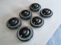
I would like to introduce and recommend a neglected 6SN7 substitute, the Raytheon
5694. It's a made for the military dual AF power triode. The 5694 = premium 6N7 GT
with separate cathode leads, like a 6SN7. It is similar electrically to a Mullard ECC32 /
CV-181, BUT with a different pin-out. The Raytheon tube actually is closer electronically to a 6SN7 than the ECC32s are. The Vfil = 6.3V @ 800ma, versus 950ma for the ECC32s and 600ma for a 6SN7 GTB. These tubes although rare can still be found for between $15 to $50 each delivered. My yield of platinum (5%) matched and balanced pairs and a single quad brought my price per tube to about $100, still a great bargain considering the fact that they are far superior to the $500 to $600 plus a pair of Mullard ECC32 / CV-181, when and if you can find them.
Raytheon has accidentally and unknowingly given the audio world a great gift.

These tubes are far less noisy than the ECC32s and deliver details like a Jazz piano with no close rival. The silent passages are as mute as you have never heard. They are also much easier on the ears, allowing for longer, more pleasant listening periods. I found the Mullard ECC32 lacking in bottom end response. My previous
6SN7 favorite flavor was the "holy grail" of the 6SN7 world, the Tung-Sol 1940s
6SN7 GT, black glass, black plates, round getters, fetching $400 to $500 a pair, when and if you can find them. Not being sentimental or indecisive, my barely used quintet quickly fetched $1,000 on the slightly used NOS market.

They require adapters or re-wiring of the octal sockets they are going into, but it's more than worth it. The required pin-out follows: Pin # 1 Cathode, 2 & 7 Filament,
3 Plate, 4 Grid, 5 Grid 6 Plate 8 Cathode. IF your making adapters, use the following pin-out. Tube base number / Tube socket number: 1 / 4, 2 /3, 3 /1, 4 / 5,
5 / 6, 6 / 8, 7 / 7, 8 / 2.
Good luck treasure hunting, I humbly await your opinions.

DAC build TDA1541A/SAA7220P/B *will take som time*

Ordered the PCB and the first component today.
I like the sound from my Marantz CD-60, even if it's only partially modded, so I wanted that sound for my PC too.
This build will take some time as I'll gather parts as I can afford them..

DAC PCB
TDA1541_DAC_PCB.jpg


SAA7220P/B
An externally hosted image should be here but it was not working when we last tested it.


and finally
An externally hosted image should be here but it was not working when we last tested it.

Question regarding a ribbon tweeter

Hey all, a ribbon tweeter like to ones in Apogee or Magnepan - if the ribbon were to be run from bottom, over top and continue down backside to bottom - open to each other within the unit - these would effectively cancel each other out and very low output would be realized, correct?

I look at the Apogee Scintilla Tweeter with the larger (2"?) mid aluminum ribbon, and the much thinner (1/4"?) tweeter ribbons on each side in front and back - the 2" mid serves to drive the mids AND separate the 1/4" tweeter ribbons in front and back from canceling each other out, correct?

I am thinking of building a 1" wide ribbon tweeter (I have a Apogee Caliper tweeter unit - no ribbon) and would like to start at bottom and continue over and down backside side - more resistance and more efficiency - but believe they will cancel each other out (if I follow the right hand rule), thus I would likely need a barrier between to prevent cancellation, yes?

Differences between Behringer A500 & A800

Hi,

I know alot of you wil ask why i would use such a amp in a home system but they are impressive value for the money, the A500was atleast. They had some flaws, as the pots who will be changed if I find 2 A500, as my plan is to bridge them and then use them to drive my elsinores, and in so creating a huuuge dynamic headroom.

My monthly income arent fat, about 350 USD as im unable to work because of a totally twice operated shouldee thats jumps out of place every single day, now waiting for surgery no 3.

So, for me this is a very good option regarding price as i have a A500 seller selling one to me for 100USD never unpacked. BUT, he asks me why i would buy the 500 when the 800 is so much more better.. It his opinion
and i need others as if the 80 extra USD för 800 will be worth it, then Ill buy the 800.

The differrence obvious to me, is the power and that A800 is class D. I unederstand D class can sound perfect nowadays but class D for 180 USD delivered, makes me a bit wondering how they can make it better than a AB for same sale price when everything else class D cost ATLEAST twice the price of A800.

If i go A500 i could beef up the PSU with some of my 48pcs 33,000usd 35x117mm Chemi Con caps when changing/bypassing/removing the pots as long as the voltage is below 50V as thats whats they rated for, ut considering power i would guess it is a higher than 50v PSU capacitor needed.


So, people please help me make a good choice here.

Finding a second A500 is no problem they are quite popular in sweden, and thereis always ebay,com/uk/de to check where i looked at a pair last week.


Anyoen whos listened to both as full register amps? Whats your opinion? Anyone else having experience either amp PLEASE jump in and help me! 🙂


Best regards and wishes from from Sweden!//Mathias

Arcing in Power Tube

I just recently finished putting together a VTA ST70. Sounds great, no hum. I’ve only got about 2 hours on it so far.

During my last listening session, about 20 minutes in, I saw a bright white flash in the top of the left rear EL34, accompanied by a moderate pop from the speaker. I used it for a few more minutes and it seemed to otherwise be fine.

Could it be a bad tube? I visually inspected the tube, and it looks like one of the grid cooling fins is too low and off center. I’ve attached a photo. Is it reasonable to assume that is the source of the problem? For reference these are the stock tubes - no name “made in China” EL34.

I’d like to try switching the tubes to different positions to see if the issue follows the tube, but I’m unclear what the risks would be. I don’t want to risk blowing up an output transformer or damaging my speakers.

Any advice would be much appreciated!

- Jonathan

Attachments

  • 40F8DEBD-6281-4A9B-8E3C-FAAE2F27444A.jpg
    40F8DEBD-6281-4A9B-8E3C-FAAE2F27444A.jpg
    738.2 KB · Views: 172
  • C5FB4CC1-8CBF-4B1E-9F6C-7B5291C07051.jpg
    C5FB4CC1-8CBF-4B1E-9F6C-7B5291C07051.jpg
    572.4 KB · Views: 180

Tim De Paravicini's HiFi World 6080 amp modded by me.

Now my kids have grown up a little, I am enjoying working through my accumulated stash of bits and pieces. I decided I had the parts to make a 6080 amp, something I always fancied, and being lazy in my old age and curious of the rare design, I decide to make an amp to the Hi Fi world 6080 circuit.
attachment.php

I was disappointed with the resulting amplifier. The two problems that troubled me were due to the ECC88 cascode. Its weedy 100k pull up gave bad slewing problems, and the unpredictable DC operating condition, brought to my attention by two randomly selected ECC88, resulted in one channel clipping high side, and the other clipping low. Not impressed.
Put the amp to one side as I pondered alternative destinies for the amplifier. Since that failure I started on some other ideas, gratuitously rats nested this time, including the SRPP circuit. Revisiting the dp circuit I realised I could change the the cascode to a SRPP. So I did, I had to pull the top valve up a bit to get symmetry, and not being familiar with the SRPP there could be a better way.
I have had various (recycled vintage) power transformer misadventures with this amp, but the first one gave me 5 watts at 5% distortion. It was getting a bit hot, so I have a lower voltage one and I now get 3.5 watts, but it works very nicely, and I would tentatively call it my current favorite amplifier. It is dynamic, it has good solid bass, and strangely to me, it gives me the best imaging from my speakers I have ever heard.
The feedback works to keep the HF up, although the amp still struggles with slewing, at least its symmetrical and can get to 20kHz sine wave. Square wave looks generally clean. I am using a multi tapped SE output transformer with the 8 ohm load on the 16 ohm tap, to give me a 1k1 primary impedance.

attachment.php

Attachments

  • 6080tdphfw.jpg
    6080tdphfw.jpg
    73.7 KB · Views: 2,041

Systemdek 110v ac motor replacement/quieter

Just wondered if there’s a nice quiet motor that would replace my existing one that’s a bit noisy on my Systemdek iixe (external 110v ac output supply)?

I don’t really want to ditch the whole power supply & get the Origin Live one as it’s quite a cost and I just want to reduce the hum coming from the motor to my plinth.

I’ve tried damping the motor with gel type rubber and bitumen backed foil used in cars. It still hums.

Or is it worth getting a spare motor to disassemble & upgrade the bearings in this thing? (if that’s even possible without serious tooling which I don’t have unfortunately).

Sorry if this has been asked before but maybe some new answers are available - like a new motor manufacturer.

Thank you in advance and “Hello Ian - I’ll respond to you soon - not had much time lately!”

Interest for genuine Semisouth SJEP120R100 curve tracer matched pairs & quads

.
We purchased a sizeable stock quite a few years back, and are finally planning to get them matched in 2019 using our own curve tracer.
Matching conditions will be 24V, 0~2A continuous mode on 60°C (+/-1°C) heater block.
https://www.diyaudio.com/forums/pass-labs/121228-f5-power-amplifier-1520.html#post4795279

We want to know how much interest there still is before deciding how many to match in the first round.
And whether pairs or quads are desired.
Would be great if you could help us get a feel.

Will take a while to match them all.
The heater block alone takes 3 hours to reach steady state temperature.


Thanks in advance,
Patrick

For discussion: user-specific Spherical Wave / Tractrix / Exponential Horns

With the following post I would like to put an idea up for discussion. Anyone who would like to participate is welcome. Even if it is torn in mid-air. But then this is an honest picture of the opinions, that is not wrong. Roughly speaking, I am concerned with the topic of spherical wave horns or horns with a different contour (tractrix, exponential, ...). I have been fascinated by this topic for over 25 years. It was then that I heard the Avantgarde Trio for the first time, and some people here are probably familiar with them. Then as now, however, they are beyond my means. I guess I'm not alone like that. That is why I started making my first attempts many years ago. Solutions made of styrofoam + plaster and wood were implemented. But were never really convincing, especially because of the modest appearance. I put the subject aside because it just wasn't satisfactory to implement. Several years have now passed. The technical possibilities have made a huge leap during this time, the interest has remained. However, I had to observe that the market for these special solutions has not really changed. There are a few providers (Jabo, ...) that offer horns for self-assembly. However, there are always a few predefined models without the possibility of influencing. I had decided for myself that I didn't want to go this way, but rather that I would like to implement what I think myself. I.e. construction of the horns, production, ... The effort involved is not insignificant. However, it is not completely impossible through additive manufacturing (3d printing). It seems feasible to me to implement this. In the course of my deliberations, the question arose whether the effort might not also be of interest to others. The market for this is small, but the world is big. And the advantage of user-specific production is not insignificant. However, this is a chicken and egg problem. You would have to make considerable advance payments to put the whole thing on a broad footing. That is why I had the idea or the suggestion to discuss this project as a crowdfunding project. In my opinion, this would be a good indicator of whether the time and financial investment is worthwhile. How do you see it? Is it just a special interest on my part? Or is it quite the opposite? It is clear that the implementation could never go through to the finished loudspeaker system. That is beyond my capabilities. Rather, it is to be understood as a supplier part for do-it-yourself construction. So in the ideal case an untreated horn which can be used by the respective user in their own application. While that's not much, it is more than has been around for years. At least that is my view of things. Because the adaptation to e.g. special geometrical conditions cannot be made with the usual ABS injection molding. However, my solution would also have its price; this cannot be done with the pure material value. I would appreciate honest feedback / contributions / ideas. If they're entirely negative, that's okay. I would then do it for myself.
Thank you very much.


Stephan

circuit modifications: APPJ PA1502A headphone amp

I'm going to be making a number of modifications to the circuit of this headphone amplifier, to achieve a pleasantly saturated type of sound.

My first questions:
How would one remove all of the negative feedback?
And how will the output impedance be affected by that change?

A schematic is here:
Dropbox - PA1502A APPJ Schematic.png

Photos of the PCB:
Any opinions / reviews on Gemtune APPJ PA1502A | Page 16 | Headphone Reviews and Discussion - Head-Fi.org

Thanks

Super Regenerative KT88s -or- Come-In Rangoon

After 20-30 hours of operation, the EH KT88s I’ve been auditioning in my SSE amps decided to get cranky, i.e. OSCILLATE.

Don’t know if it was a change in the tube or a change in environmental noise, but it definitely was the KT88s; same VFO (controlled by 100K volume pot) with the 12AT7 pulled).

These amps were build 8-10 years ago, so the grid stopper resistors were on the TOP side with the sockets (not my current practice), so out came both boards to see how much grid stopper I need.

I know that George likes him some crazy-low grid stoppers, but then he’s always building amps that could do double duty as AM band transmitters, so I take that with a grain of salt.

(A) installed single screw terminals on the backside of the board to allow changing the grid stopper resistor
(B) slapped some 1N4007s on the high tension leads (the “DYNACO” mod) so I can comfortably use 5AR4/GZ34 rectifiers; I told you, these are OLD boards.

If you’re contemplating an SSE amp, I would tell you to use these single-point screw terminals for (a) power tube cathode resistors (b) power tube grid stoppers and maybe (c) coupling cap and (d) C1, if you think you can see the need for changing B+ sometime...

I have 1K stoppers in there now, which has eliminated about 80-90% of the oscillation (judging by the sweep of the vol pot). Looks like ~1500 or 2k ohms might be called-for. Would like to use as low a value as possible, but trying to avoid dragging-out the scope and dummy load; it’s the shop amp after all.

Has anybody else seen this with the EH KT88s in the SSE amp?
I’m a little surprised, but I do remember thinking that George’s stoppers were a lot lower resistance that the 1K I was used-to at the time....

Attachments

  • B32E18CF-A0AD-4A1D-8317-3E8770D44461.jpeg
    B32E18CF-A0AD-4A1D-8317-3E8770D44461.jpeg
    397.5 KB · Views: 192
  • CED9C6BB-8416-4BDE-930A-DD496025BE7B.jpeg
    CED9C6BB-8416-4BDE-930A-DD496025BE7B.jpeg
    493.4 KB · Views: 191

USB scope project

Been working on a cheap low frequency dual channel USB scope for audio work.
Designed the pcb and got it made.
Got stuck into software for PC and a PIC32mx microcontroller.
Tried clocking a2d at full speed just reading outputs but i twas terribly noisy, must have been trying to read as data was changing.
So clocked a2d in software and read each channel after a2d was clocked.
Much cleaner signal now. But still a bit noisy. Spotted a2d decoupling wasnt close enough so fixed that and nice clean signal now.
However, I was disappointed with max speed of scope being about 3 mega samples/s. I looked up i/o instructions for pic32mx and I found some faster ones. That improved the speed quite a bit. I then spotted an instruction that can set/reset multiple i/o pins at the same time.
This brought up my sampling speed to 11 mega samples/second over two channels.

Philips CD880

Hey all, new here and looking for some help!

I have an older Philips CD880 that I purchased new. It been sitting in its box for the last probably 10yrs (I know, I know). Anyway, I recently decided to install it in my second system and the tray won't close. I took it apart and found the issue.. its a switch. There are two; one for open and one for close and the one for close is broken.

I've found the part number and would be willing to buy a whole tray assembly however I cant even find that. The part number from the Philips service manual is #4822 276 11277

Any hints or clues on where I may find one?

Luxman DA-07 and splines

Browsing some spline papers I came across a reference to a work on splines in DA conversion. It seems like Masaru Kamada has made some DAs using splines, including the Luxman DA-07.

I'd really like to know more about this DAC. Going to library on Monday to order more papers. Meanwhile, does any one of you guys know more about this DAC or others using splines?


Greetings,

Børge

Crossover question

I already have a 200 hz second order low pass for the Eminence Alpha 15a. using a 68uf cap and a 9mh inductor. But I want to try a first order low pass at 80hz. Off the top of my head I figured I would just need a inductor of about 20 -25 mh. But low and behold when I ran the calculator here it said for a Bissel at 80HZ all I needed was 11.7 mh could there calculator be in error ?


2-Way Crossover Calculator / Designer

Different top plate & wood base for 2A3 parafeed

Well, I thought this might give a little fun to see for other DIYers.
My local DIYers like this. 😀

Top plate with hinges and damper. Damn convenient to temper with.
You don't have to pick it up and put it upside down and open the bottom plate...

It's D3a trioded to parafeed bifilar interstage, then to 2A3 resistor loaded parafeed SE.
B+ is 48V Cisco SMPS in series I did after Greenvalves.

Attachments

  • 991293460_F0HlvgXZ_2021-03-09_11.27.58.jpg
    991293460_F0HlvgXZ_2021-03-09_11.27.58.jpg
    592.8 KB · Views: 278
  • 991293460_s0Ux2z9k_2021-03-09_11.18.08.jpg
    991293460_s0Ux2z9k_2021-03-09_11.18.08.jpg
    824.5 KB · Views: 271
  • 991293460_r1VImfKx_2021-03-09_11.18.29.jpg
    991293460_r1VImfKx_2021-03-09_11.18.29.jpg
    931.8 KB · Views: 277
  • Like
Reactions: ziffel

Pass D1 DAC question

Hello,

I try to build the PassLabs D1 output stage for an PCM1794 DAC. I searched in the old forum threads, but could not find clear answers to my questions... I hope, that someone can help me.

The original circuit is designed for the PCM63 chip, whose current output is +/-2mA. The current output of the PCM1794 is 7.8mA PP. So the output of the D1 in combination with the PCM1794 chip is much to loud. As an solution i would like to reduce the gain of the D1 stage. I read that the gain of this stage is set by the two resistors R27/R34 which are 1K5. To lower the gain i lowered these resistors to 100R, which gives me still to much gain.

So my first question is: how low can I go for R27/R34 without any drawbacks? For example: do i have to change the values of R26/R33 also to avoid that the current through Q3/Q6 is getting higher?

And i found that the resistors R27/R34 form an low pass filter with C15/C16 0.0027uF. This filter has to be recalculated if R27/R34 are changed. If I feed an lowpass-filter-calculator with the values, i find the cut-off frequency at about 40KHz. And vice versa for R27/R34 at 100R, C15/C16 should be 0.04uF to reach cut-off at 40KHz.

My second question: can anyone confirm my calculations?

Thank you for your suggestions and help!

Regards,
Michael

attachment.php

Attachments

  • schema.png
    schema.png
    35.3 KB · Views: 1,315

Earthquake MiniD1000.4 clips bridged (TDF8951TH)

Have an Earthquake MiniD 1000.4 that clips the rear channel output when bridged at 4ohms and at a moderate level of output.
Got this amp in protection and discovered the rear channel TDF8591TH IC was defective. I was not able to locate a single chip from any reputable suppliers so I purchased one from Dalbani Corporation on ebay. I installed the IC and all four channels have clean output. I didn't test the amp bridged or even with a subwoofer before selling bit to a friend. He reported to me that the rear channels are clipping when connected to a 4ohm subwoofer load. I tested the amp and witnessed the same occurrence. The front channels do not have this issue.

Attachments

  • IMG_20210324_135756.jpg
    IMG_20210324_135756.jpg
    1,014.1 KB · Views: 79
  • IMG_20210324_135739.jpg
    IMG_20210324_135739.jpg
    1 MB · Views: 69
  • IMG_20210324_135726.jpg
    IMG_20210324_135726.jpg
    1,001.2 KB · Views: 76

Tang Band w8-2145 as a full-range in center

I've tried different centers with my W8-2145 based Back Loaded Horn L & R speakers, but to no avail.

It certainly occurred to me, I might have better success putting the same driver in a center/horizontal cabinet. It wouldn't need to go too low, but perhaps I could load the back-wave and get some useful low frequencies, it'll be ok. Most important is the identical sonic signature 200Hz and up, I think.

Thoughts, and cabinet suggestions?

Thanks.
Daniel
Singapore

Wright Mono 8 Schematic & Operating Points

Does anyone have operating points or, even better, a schematic for the George Wright Mono 8 300B SET?

I'm currently developing a 300B SET inspired by his WPA 3.5 circuit (which I found here in a post by ClefChef), which is the same as the Mono 8 but for a 2A3. Mine would use the Magnequest TFA-204 (3K, 60mA), so I'll probably run the 300B at the 350Vak/60mA op point. But I'm curious as to how George set up the 300B for the larger FS-030 and more specifically the 6SN7 input stage.

I imagine the input stage is not much different from the WPA 3.5 but it would be good to know.

Thanks,

Jeff

Mosfet Matching for F5T V3 - Correct Voltage/Heatsinking/Resistor

I've had trouble finding mosfets that are properly matched for use in my F5 Turbo V3 monoblocks. I bought several sets from reputable sellers, but I don't believe that they were matched under the conditions in which I am using them. This has caused me to blow a few sets of outputs when biasing the amp to a level where the heat sinks to approach 50C. I believe that the high bias on an unmatched, current-hogging mosfet has caused one or more of the diodes to conduct and led to smoke.

I am considering removing the diodes altogether, as some have suggested, but thought I would first try matching my own set of mosfets first under real world conditions.

I've read many of the various mosfet matching threads, but I haven't found an answer to the basic question of how to simulate the real world conditions of the mosfets in my F5 Turbo.

I intend to use the basic technique set forth by Nelson Pass in the following article, which many others have used:
https://www.firstwatt.com/pdf/art_matching.pdf

But my F5 Turbos have 41V rails, so I have the following questions:

1) Should I use a 40V power supply when testing the mosfets? Or is 15V enough?
2) How much current should I aim for with the I=(V-4)/R1 formula set forth in the article?
3) How many watts does R1 need to be rated for if the voltage is increased to 40V?
4) I plan to test the mosfets while they are screwed to the heatsink. How long should I let them heat up before taking the reading? Should I let them completely stabilize, which could take a while?
5) How closely should they be matched? I've seen 30mv, 10mv, etc.

I would really appreciate some help on this.

Thanks

FS: Electronic Crossover

FS: Electronic Crossover-Sold

SOLD I am no longer using my 2 way crossover so it's up for sale. I used 2 Marchand xm9 boards with a ps-10 power supply. This is a 24 dB/octave crossover. Here is a link for more information.
XM9 Electronic Crossover
I am including 3 sets of frequency modules, 90,120 and 200hz.
Enclosed in nice case.
Manual included.
$150 plus shipping. Venmo preferred but can take paypal.

935385d1616608508-fs-electronic-crossover-x0ver-inside-jpg
935386d1616608699-fs-electronic-crossover-xover-jpg
935387d1616608508-fs-electronic-crossover-xover-front-jpg
935388d1616608508-fs-electronic-crossover-xover-manual-jpg


Hope the pictures work, if not I can email them to interested parties.

Thanks for looking

Attachments

  • x0ver inside.jpg
    x0ver inside.jpg
    32.5 KB · Views: 262
  • xover back.jpg
    xover back.jpg
    25.7 KB · Views: 288
  • xover front.jpg
    xover front.jpg
    32.8 KB · Views: 243
  • xover manual.jpg
    xover manual.jpg
    26.5 KB · Views: 247

Active WMTM(S)W

I've just finished off a build for a pro audio setup using 12" B&C coaxials for mains, 8" coaxials for monitors and an 18" sub. The system sounds great but definitely isn't suited to running at low volumes inside my lounge room😀. I did hook it up as a 4.1 surround system, nice cinema level sound, but im sure the neighbours didn't appreciate it and the amp noise (powersoft m28q and K3) was also far to load for normal listening levels.

Anyway, it's time to start a new project to keep myself busy.

I had been following this build and really love the concept:
Scanspeak 4 Way Active DSP Build with Illuminator/Revelator Drivers

Im looking for some advice on building a slightly scaled down version using 8/4/T/4/10" drivers in a single piece enclosure. Looking at the following drivers:

Tweeter: SB acoustics SATORI TW29RN-B-8
Midranges: 2x SB acoustics sb12mnrx2-25-4
Woofer: SB acoustics SB23NRXS45-8
Subwoofer: SB acoustics SB29NRX75-6

I have a minidsp 2x8 to run the crossovers and for the moment a Lab Gruppen C20:8x (8x 250w) to drive everything during testing. I would need to swap this out for a hifi amp, probably a Nord or KJF ncore 8 channel.

I have access to a CNC machine so would be using a translam construction. I originally made up a design with a front face that is cut separately:
Fusion

I will probably ditch the seperatefront face for simplicity.

Would love some feedback on the driver selection.

External controller for Buffalo-IIIsePro38 - i2c problems

Hi everyone

Im setting up an Arduino Due as external controller for my Buffalo-IIIsePro38 and I cannot get the i2c working.

Using the Wire library example scanner, I find a single device at address 0x20. I expected to find 0x48 or 0x90.
Turning off the BIII board results in no devices found so I know it is finding something on the BIII.

Writing directly to address 0x48 just gives result code 2 - NACK.

Code:
Wire.beginTransmission(DAC_ADDR);
Wire.write(7);
Wire.write(0);
byte res = Wire.endTransmission();
Serial.println(res);
What am I doing wrong here?

SoundMagus X3500, Excursion HXA5K output PWM not working

This amp has 2 Optocoupler driver cards on the output.
(photo attached, pin configuration from left to right)
Pin 1: GND
Pin 2: Input PWM drive (coming from a 74HC00 IC)
Pin 3: Power supply transformer PWM
Pin 4: VCC
Pin 5: Output PWM drive for bank 1
Pin 6: Output PWM drive for bank 2

One side of the amp does not want to create an OUTPUT drive PWM going to the gates of the IRF640N's. Even putting in a 100% good driver card results in no usable PWM gate drive.

The driver card receives a PWM drive input on Pin 2.
Also the power supply PWM on Pin 3 is present.
The GND and VCC is also present on Pin 1 and 4.
There is just no output on Pin5 and Pin6

Almost every part on the output PWM circuit has been replaced (all the 2x and 2t transistors, 74HC00, 6n137 optocoupler). All resistors on the driver card has been checked and are OK.

Attachments

  • PHOTO_20210223_115141.jpg
    PHOTO_20210223_115141.jpg
    468.3 KB · Views: 126

Webcor 2611 morph into practice amp

My son and I are going to build his first ever tube powered guitar amp. He has a ss line6 spider 4 75 that he uses to play with the band with now that keeps up with the drummer. It models gobs and tons of different sounds kinda ok. However, like most midi/ss amps, it just can't deliver that tube amp sound. It is too loud for his bedroom, where he studies and plays his computer and guitar most of the time. We whipped up a little op-amp/ss chip amp at first, but it is too dry, and doesn't have that "tube sound" when it distorts. And guess what? He likes bluesy "crybaby" sounds and "metallica" heavy metal distortion.

We went to guitar center so he could figure out what he likes in tube amps, and the results surprised me. Contrary to my assumption that he would be drawn to the mesa/marshall amps, he has gravitated towards the vox and orange amps. Between the ac30 and the tiny terror, he probably spent an hour going back and forth. He could not pick a favorite, the vox sounded better clean and the orange sounded better distorted. When pushed into a choice, he said he would take the vox and add pedals if he had to choose. But it was too loud.

Fresh Mods

Hello all

We would like to introduce two new moderators. Sangram from India and AllenB from Australia. Good long time diyA members. Their time zones are nicely spread. Thanking them for accepting the invitation.

*We would also like to thank jazbo8 & TonyTecson for their positive long tour of duty as they retired during the recent period.
Projects by fanatics, for fanatics
Get answers and advice for everyone wanting to learn the art of audio.
Join the Community
507,801
Members
7,888,980
Messages

Filter

Forum Statistics

Threads
406,269
Messages
7,888,980
Members
507,801
Latest member
TMCK001