Hello,
10 years ago I made a amp with two STKs 4241 II.
A few months ago I decided to rebuild it ,since the first build was hasty and had some noise.
I finished it a couple of days ago and it works fine except some issues.
First one is that there is too much treble.I connected a pre amp I made with a NE5532 and I have to cut down 20-25% of treble to make it sound good.That happens either with the preamp(without cutting down treble) or with a signal straight to the amp.
I guess it has something to do with the input capacitor.Everything on the board is what is stated on the datasheet so the capacitor is a 2.2uf.
Second problem is a bit of a hum when nothing is connected but that's not too annoying,as it's not too loud.It could be a ground loop and I will check my grounding again.Note that I star grounded everything.
Third issue is that when input is connected then more noise appears,at different frequency, that increases when I increase the volume.The volume is adjusted by a pot connected to the RCA.Could that be RF interference?Note that the front and rear of the chassis are plastic as they are 3D printed.Chassis is grounded.
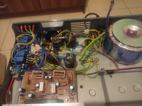
I will upload later some photos from the amp and a drawing of how everything is grounded.
I have a toroidal 600VA transformer ,two STKs on 2 different boards,the input signal cable is shielded,however some 220V cables are nearby so that could be the reason for my second problem.
Thanks!
10 years ago I made a amp with two STKs 4241 II.
A few months ago I decided to rebuild it ,since the first build was hasty and had some noise.
I finished it a couple of days ago and it works fine except some issues.
First one is that there is too much treble.I connected a pre amp I made with a NE5532 and I have to cut down 20-25% of treble to make it sound good.That happens either with the preamp(without cutting down treble) or with a signal straight to the amp.
I guess it has something to do with the input capacitor.Everything on the board is what is stated on the datasheet so the capacitor is a 2.2uf.
Second problem is a bit of a hum when nothing is connected but that's not too annoying,as it's not too loud.It could be a ground loop and I will check my grounding again.Note that I star grounded everything.
Third issue is that when input is connected then more noise appears,at different frequency, that increases when I increase the volume.The volume is adjusted by a pot connected to the RCA.Could that be RF interference?Note that the front and rear of the chassis are plastic as they are 3D printed.Chassis is grounded.
I will upload later some photos from the amp and a drawing of how everything is grounded.
I have a toroidal 600VA transformer ,two STKs on 2 different boards,the input signal cable is shielded,however some 220V cables are nearby so that could be the reason for my second problem.
Thanks!
Are the STK original?
If over gain, that could be the problem...Or high idle current from input. Put a 3.3 or 10 ohm resistor to drop pre amp output voltage (input of STK).
And what are the supply voltages, put 0.1 uF in parallel with mains capacitors to reduce noise.
If you are close to the limit on the supply, this can happen.
Reduce the mains voltage with a variac and see if it helps.
Then you will need to adjust supply voltages.
Are the STK original?
I guess they are but I can't be sure.I bought them from a trustworthy shop 10 years ago.Is there a way I can find out if they are original?
If over gain, that could be the problem...Or high idle current from input. Put a 3.3 or 10 ohm resistor to drop pre amp output voltage (input of STK).
The issues appear even with no pre amp,just with a source connected to the amp.I have a 47K pot as a volume adjuster at the signal's path before the STKs input and at low volumes it does help and reduce the noise but when I max it,then noise appears.
And what are the supply voltages, put 0.1 uF in parallel with mains capacitors to reduce noise.
Supply voltage is +-50V.I will try that but I don't think that the noise is from the power.The main capacitors are 2X10000uf at each rail.
If you are close to the limit on the supply, this can happen.
I'm doing the tests with just one speaker 70W/8Ohms so the power supply is not working on limit.
Reduce the mains voltage with a variac and see if it helps.
Then you will need to adjust supply voltages.
I started doing some tests and removed everything from the input of the STKs.
When I connect something at the input then noise appears.Even a single extension cable does it.
The noise is at high frequency and I think that whan triggers that is also responsible for my problem with the treble,as it is a bit distorter at low volume and there is too much treble at higher volume.
The STK module 4241-II is rated 120 watts per channel at +/- 53 volts at 8 ohms.
So +/- 50 is close to the limit.
Put a bigger rated speaker, heat sink it properly - most dangerous if they overheat, they act odd, and sometimes they take the speakers and transformer with them.
Your issue sounds like a noisy input, stray noise somehow, and too much gain.
Put a 63 or 100 volt rated 2.2 uF cap in input, and try to put a 47 or 100 ohm to ground in series or parallel to it, see what happens.
Also try a 0.1 uF in parallel as a treble filter.
But do the heat sink part first, use a thin film of heat sink compound. Fasten it properly to the heat sink.
Sometimes permanent damage happens if overheated, they work, but not well, and fail early.
Last edited:
Unfortunately I don't have a bigger rated Speaker.
Cooling is ok ,I have attached a big heatsink with thermal pad and a 8cm fan.It barely gets hot with the one speaker.
I have added protections with uPC1237 at the speakers because I know that the STKs tend to do that.
As I said the problem is the high frequency noise when input is connected.
I will try to add what you said to the circuit.
Could it be a problem with the inductors?
I realized that I needed a n=23 air coil and mine has only 10.And according to the datasheet the coil is there for high frequency oscillations.
Earthing a toroid is an unknown for me due to possible formation of ground loops which can blow those.
Please check again, the resistors might not be spot on, and leaky capacitors do exist.
Is the sound like a whistle (continuous) or intermittent?
Whistle means component fault, intermittent means dry joint or loose contact somewhere.
Please check again, the resistors might not be spot on, and leaky capacitors do exist.
Is the sound like a whistle (continuous) or intermittent?
Whistle means component fault, intermittent means dry joint or loose contact somewhere.
So,I did some tests.
Removed the input wires at all.
Replaced the coils with the proper ones.
When no input is connected,noise is actually pretty low.
However there is some DC offset.
I measured just one STK and on one channel it's 130mV DC and on the other channel it's 150mV.
Could this be the reason?
Also when I connect a wire on the input noise appears and I have 80-100mV AC out.
The noise is always coming from the tweeter so I guess I have some high frequency oscillation?
What I've build is thisDoes the amp have an RF filter on front end ?
STK4241 STK4201 STK4221 STK4211 STK4231 Amplifier Circuit - Electronics Projects Circuits
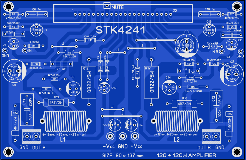
So I guess there is no RF filter.
Is there any simple circuit so I can add one?
Same speaker on a Marantz amp plays just fine.No distortion and treble is just fine.100-150 mV DC off load is barely okay
Check on load.
Also see if tweeter connected properly through good quality cross over, sometimes it is just a cheap capacitor!
I tried a couple of things at that Marantz amp and figured that noise appears there too when input is connected.Less than the STK but I guess that's because the STK has more gain.
So I guess the noise with the input thing,is normal and I should focus on finding out why there is too much treble and also why treble sounds a bit distored on low volumes.
Try a source like a PC, and the playback program should have an equalizer, like Winamp did.
Then adjust the volume, and frequencies.
The problem seems to be over gain and wrong equalisation, then after finding the frequency and harmonics, work on the capacitor that matches the input requirements of the STK module.
See what the RIAA curves are, and try to trace the fault.
Could be the circuit you made is a faulty design, like some 3886 ones.
See if you can find the Sanyo data sheets or application notes. Compare those with what you have done.
Problem was that Sanyo never put their mark on OEM chips, only on OE service replacements and for market use, so you can't tell at first glance.
The finish is better, and there is a glass epoxy PCB on the originals, and they are a little heavier than the fake ones.
Anyway, they are mostly obsolete.
Last edited:
I have the datasheet,it's this one
STK4241II pdf, STK4241II description, STK4241II datasheets, STK4241II view ::: ALLDATASHEET :::
And the components are the same.
I think I'll wait for the oscilloscope I have ordered,so I can find out the frequencies and see if I can balance them out by changing some components.
I'll try it with the equalizer as you said too.
It should be a genuine STK,mainly because the shop I got them from is trustworthy and would never be selling fake stuff.
Does the amp have an RF filter on front end ?
Apparently it does have an RF filter on the front.
Put a Japanese, 3.3 or even 4.7 on the higher side.
Check your input is about 250 mV.
Put a balancing load on the other channel.
You can use good quality European ones, 105 degrees quality.
And you can get plenty off old computer motherboards...6.3 and 16 volts. from 1 to 2200 uF.
Enjoy experimenting...put extension wires and alligator clips so you can experiment without having to solder, just keep polarity in mind.
Have fun
- Status
- This old topic is closed. If you want to reopen this topic, contact a moderator using the "Report Post" button.
- Home
- Amplifiers
- Chip Amps
- Noise when input is connected,too much treble on STK4241II