Hello,
I try to build the PassLabs D1 output stage for an PCM1794 DAC. I searched in the old forum threads, but could not find clear answers to my questions... I hope, that someone can help me.
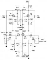
The original circuit is designed for the PCM63 chip, whose current output is +/-2mA. The current output of the PCM1794 is 7.8mA PP. So the output of the D1 in combination with the PCM1794 chip is much to loud. As an solution i would like to reduce the gain of the D1 stage. I read that the gain of this stage is set by the two resistors R27/R34 which are 1K5. To lower the gain i lowered these resistors to 100R, which gives me still to much gain.
So my first question is: how low can I go for R27/R34 without any drawbacks? For example: do i have to change the values of R26/R33 also to avoid that the current through Q3/Q6 is getting higher?
And i found that the resistors R27/R34 form an low pass filter with C15/C16 0.0027uF. This filter has to be recalculated if R27/R34 are changed. If I feed an lowpass-filter-calculator with the values, i find the cut-off frequency at about 40KHz. And vice versa for R27/R34 at 100R, C15/C16 should be 0.04uF to reach cut-off at 40KHz.
My second question: can anyone confirm my calculations?
Thank you for your suggestions and help!
Regards,
Michael
Attachments
Last edited by a moderator:
Look here.
http://https://www.diyaudio.com/forums/digital-line-level/154866-classic-pass-labs-d1-ess-dac-9.html#post2152628
(Hopefully the link works...)
http://https://www.diyaudio.com/forums/digital-line-level/154866-classic-pass-labs-d1-ess-dac-9.html#post2152628
(Hopefully the link works...)
I read that the gain of this stage is set by the two resistors R27/R34 which are 1K5. To lower the gain i lowered these resistors to 100R, which gives me still to much gain.
So my first question is: how low can I go for R27/R34 without any drawbacks? For example: do i have to change the values of R26/R33 also to avoid that the current through Q3/Q6 is getting higher?
I can't see any drawback to reducing R27/34 as low as you need to go to get the amount of gain that suits you. No need to change R26/33 unless you want to reduce them to run the MOSFETs at higher bias (and hence get more gm).
And i found that the resistors R27/R34 form an low pass filter with C15/C16 0.0027uF. This filter has to be recalculated if R27/R34 are changed. If I feed an lowpass-filter-calculator with the values, i find the cut-off frequency at about 40KHz. And vice versa for R27/R34 at 100R, C15/C16 should be 0.04uF to reach cut-off at 40KHz.
My second question: can anyone confirm my calculations?
They seem fine to me.
Hello Pierre, hello abraxalito,
thanks for your answers. I'm glad, that my thoughts and calculations go in the right direction...
I read the thread of the link you sent me, Pierre. There is one thing i don't understand. What do you mean with: "I could not trim the output voltage to 1.65 V without reducing R24, R31 from 100 K to 68 K." What is this output voltage?
Do I get you right, that if lowering R27/R34 it has only an effect of the gain, not the bias, and that i correct C15/C16 accordingly? That would be easy to accomplish....
And if I would like to increase the bias, i lower the value of R26/R33 and change the C40/C55 values accordingly.
Thank you in advance!
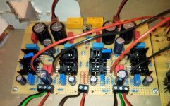
The picture below is the prototype stage in an banana box. Sounds great!
Attachments
It was a while ago, but I believe I meant "input voltage" not "output voltage" and 1.65 V is the desired DC voltage of choice for the "output" of that particular ESS DAC.
I believe the rest of your reasoning is correct.
I believe the rest of your reasoning is correct.
And if I would like to increase the bias, i lower the value of R26/R33 and change the C40/C55 values accordingly.
I'm unclear about the role of C40/55 so not sure if they really need changing when the bias is increased. Perhaps 'suck it and see' is the best approach.
If I recall correctly they do form another low pass filter, this one at the input of the I/V concerter. This is in addition to the low pass filter at the output of the I/V. They have different cutoff frequencies. This is simple and elegant.
If you want to throw away some gain, have you considered simply shunting VOL+ and VOL-? You can start with say 500 ohm and adjust from there.
The reason I changed the four resistor values was because the ESS chip outputs four times the current of the PCM63 and this was getting close to the 9 mA bias current going through the MOSFETs in the stock circuit. So I tripled the bias current to be safe.
Last edited:
Yes, I was thinking about putting an resistor or pot between +/- Vol, but didn't like the idea. After some tests and measurements I ended up with 400R for R27/34 and 0.01uF for C15/16. Bias is still in the range of the original construction and the changes do not effect the sounds (as far as i can hear...).
Thank you very much for your help!
Michael
Thank you very much for your help!
Michael
- Home
- Amplifiers
- Pass Labs
- Pass D1 DAC question


