A different overcurrent-protection for LLC

To the best of my knowledge standard LLC smps is typically protected against OC by either: Split-capacitor and clamp-diodes to rails or voltage-measurment of the capacitor-voltage.

The Split-capacitor-diode-idea is simple but limits the voltage over the caps and for some designs that may be a problem?

The voltage-over-capacitor-reading is proven and tested, but requires a high-voltage-capacitor to work?

So late last night i got en idea: if the LLC is implemented with a seperate series-inductor we can directly measure the current in this by adding a single (isolated) winding and putting a suitable resistor across the single winding. Voltage over the resistor is then a true reading of the current in the LLC-loop.
The voltage could easily be scaled and fed to the CUR-limit input of controllers like L6599.

Is this an old idea? - i could not find anything on google, but that is probably because I dont know the correct words to search for.

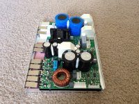
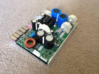
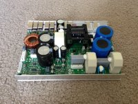
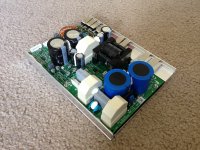
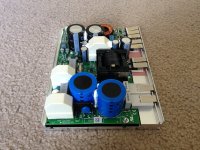
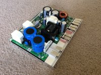
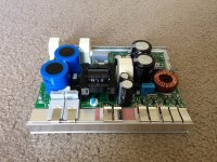
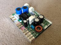
I have a working LLC on the workbench and Im tempted to test the idea, but let me hear your thoughts.

Kind regards TroelsM

FS: Bang-Olufsen (B&O) ICEpower 500ASP D-Class Amplifier Modules

Attachments

  • IMG_3798.JPG
    IMG_3798.JPG
    900.3 KB · Views: 1,705
  • IMG_3799.JPG
    IMG_3799.JPG
    818.6 KB · Views: 1,682
  • IMG_3800.JPG
    IMG_3800.JPG
    798.4 KB · Views: 1,648
  • IMG_3801.JPG
    IMG_3801.JPG
    899.3 KB · Views: 1,648
  • IMG_3802.JPG
    IMG_3802.JPG
    784 KB · Views: 1,578
  • IMG_3803.JPG
    IMG_3803.JPG
    901.3 KB · Views: 375
  • IMG_3804.JPG
    IMG_3804.JPG
    799.6 KB · Views: 369
  • IMG_3805.JPG
    IMG_3805.JPG
    794.2 KB · Views: 436
  • IMG_3806.JPG
    IMG_3806.JPG
    605.5 KB · Views: 495
  • IMG_3807.JPG
    IMG_3807.JPG
    683.9 KB · Views: 505

Vintage Lowther PM2 Recone?

Saved this gem from the garbage collectors.
Looks like it was re-coned at some point. Have not tested DCR yet.
Came out of a Brociner corner horn. Hope to use as a mono
or better yet find it’s twin some day. Not bloody likely! The owner’s
eighty year old eyes lit up as he recalled buying the speaker and building a Heathkit Tube
amp to go with it. He then told be that all could bettered by a
a pair of Bose speakers. I smiled in apparent agreement and thought to
myself how rough it is to get old.

Attachments

  • B81D860F-83D2-4C75-83C4-683772EB3372.jpg
    B81D860F-83D2-4C75-83C4-683772EB3372.jpg
    87.1 KB · Views: 434
  • 31571AE7-D9EE-4237-BE5D-633B0D6C420C.jpg
    31571AE7-D9EE-4237-BE5D-633B0D6C420C.jpg
    75.6 KB · Views: 471
  • 15B445C7-1EA9-4D6E-8AA6-55B6A5BFBF1E.jpg
    15B445C7-1EA9-4D6E-8AA6-55B6A5BFBF1E.jpg
    83.9 KB · Views: 490

TU-8500 Noise

Hello,
I am looking for some help with diagnosing my new Elekit TU-8500. I just finished building the kit. I went through the operation check and everything works except there is a hiss/static sound coming from my speakers. It is loud enough that I can hear it sitting 9 feet from my speakers.


Some Info and might help:

- Both channels are affected.
- The hiss is present whether or not I have a source hooked up to any of the inputs.
- Hiss stays constant no matter what the volume control is at.
- Changed power cords.
- I moved the pre-amp to a different location to see if I was getting interference.
- I swapped in another pre-amp and it was silent.

Any ideas would be appreciated.

Thanks,
Mike

NAD C300

Hi All,

I'm playing with a faulty NAD C300. One of the MOSFETs died and had blown the 5 amp fuses. I've replaced the MOSFET but before powering up the amp fully, I'm checking the unit for other issues. Looking at the supply voltages on the power supply board (with the amp board disconnected) I'm not getting the rectified voltages I expect - but I'm struggling with a common ground reference. Fwiw I believe the transformer is good. It's windings seem to be correct when each winding is measured to its corresponding CT and pair - for both volts and resistance. This poses me two questions I'd appreciate advice on.

First Question: The circuit diagram in the service manual shows the centre tap of both the secondaries being connected on the power supply board and forming ground - but they're not connected until the amplifier board. I assume it's ok to connect them on the power supply board while testing so I have an easily accessible ground reference since they are connected but by a different part of the circuit? Trying to hold a multimeter probe onto a header pin is asking for trouble...

Second Question: Another deviation from the service manual is that Ground is directly connected to Chassis on the amp board. The service manual shows different types of separation between Ground and Chassis depending on where the connection occurs in the circuit but no direct connection. Is there a reason why the chassis (which has no connection to Mains Earth / Protective Earth) would have been directly connected to circuit ground? Is there any reason I shouldn't reinstate the separation shown in the service manual?

I have attached images showing the power board layout and relevent circuit diagram. All replies gratefully received.

Attachments

  • Screenshot_20210119-182359_Adobe Acrobat-01.jpeg
    Screenshot_20210119-182359_Adobe Acrobat-01.jpeg
    273.7 KB · Views: 157
  • Screenshot_20210119-182508_Adobe Acrobat.jpg
    Screenshot_20210119-182508_Adobe Acrobat.jpg
    588.5 KB · Views: 162

4-5,25inch auto speakers suited for indoor use in enclosure

Ive read that carspeakers are designed for infinite baffle. Do anyone know of 4-5,25 in coaxial autospeakers suited for mounting in a box for hifi use in a 2,1 system. Has to be current models

I ask cause carspeakers are often dirt cheap and I need the protection cover for my application.
They need to play down to 100 hz zero db down or close.
Volume has to be reasonable for musiclitening in sometimes larger rooms
Any suggestions? Cheers!

Dr Thomas Power Amp Improvements

Hi
I have a couple of old MF Dr Thomas power amps, both of which are still working well and I'm keen to give them a thorough refresh to keep them reliable, hopefully improving the sound quality as well! In original form, they sound fairly relaxed with good solid bass and a rather effortless power delivery. Surprising poke for their rated 120w RMS.
Has anyone experience of these amps? They seem to be very simple in their design and construction - which appeals a lot.
Initial plan is to fit new, larger smoothing caps, a better bridge rectifier, replace all the caps on the circuit board with higher grade items and replace all the rather flimsy internal wiring with decent stuff. What about diodes and transistors? Any likely improvements to be made there?
Any recommendations as to what make of components and any other mods that can be carried out would be gratefully received.
Would anyone be interested in seeing photos of the refurbishment?
Thanks in advance!

Another corner line array, 28 TC9FD18

Hi there!

After moving to a new house I decided to build a new set of speakers. My wife had been complaining on the previously somewhat bulky speakers and I was therefore planning on something that didn't need to take up so much floor space and could be placed into the corners of the room. My thought was going in the direction of a full range line array so I started to look for inspiration. Soon I found wesayso's gigantic thread on this forum, and this has been a main inspiration for this project.

My plan is to build a big bookshelf, covering most of the wall and integrate the speakers on the sides. The room width is about 2.8 meters and the listening area will be about 3 meters from the wall. As of now, the room looks like this:

Foto rum.jpg

Ceiling height is about 2.5 meters, so there is room for 28 TC9FD18 drivers on each side. 4 sections in series with 7 drivers each in parallell should do. Minimum driver impedance is 7.75 ohms, so the resulting impedance would be 4.4 ohms.

As can be seen in the photo, there is a big window on the left. The first reflection point from the right speaker will be right on this window. No chance of stuffing the window with absorption...so I got this idea of trying to absorb the sound close to the speaker instead. By doing so I want to narrow the horizontal dispersion and avoid any early reflections in the listening spot:

Rum.JPG

It would look something like this:

Bokhylla.jpg

The plan so far is to build four separate cabinets for each side, containing 7 drivers each, and stack them. 2.5 liters internal volume per driver and 16 mm thick MDF for cabinet walls. Drivers front mounted and then (a better looking) second baffle made of oak attached on top of that. One section would look like this:

Sektion.jpg

This is the plan for now, but I'm sure some things will change in the process. 😉 70 drivers (some for future ideas, like ambience speakers etc.) ordered and are on the way!

Drivers measurement methodology and real world application

Hello,

This might be a pretty basic question to some, but I'm unable to find an usefull answer to it.

When a driver manufacturer publish it's driver's frequency response diagram, in what environment and how exactly are those results acquired? Do they mount the driver on some kind of infinite baffle? (Outside wall of the room perhaps?)

Reason for asking is... when I mount that driver to an open baffle, or if I just hang it with no baffle at all, what kind of a readout can I expect? (Provided that the measurement are taken outside with no reflection points, except for the ground perhaps)
I've seen some videos where a downward slope to lower frequency is displayed, with a peak in the middle of the spectrum. Would that happen even to the driver that's measured dead flat on specs?

Thanks for your help,

Stefan

Mouser delays

Just an FYI for anyone from Europe (and maybe US?) ordering from Mouser at present... they have looooong processing times at present due to both snow in Texas and all the other crap thats happening in the world. They couldn't even give an estimate of how far behind they were earlier today.

Not thrashing Mouser, they have usually excellent service IMHO (although I'm not a very frequent user), but its best to know there are delays right now before waiting and waiting on something for a project. Its been 8 days now and my order is still in processing.

Rockford fosgate 800a2 dc offset at both terminals

Hey guys I’m looking at this punch 800a2 board here the problem is there 54.14vdc at both channels. I was in the works of repairing one channel as you can tell by the picture. I installed some fets to test everything and so far it play clear and clean. Then both channels ended up dc voltage. Neither outputs appear to be shorted from left to right pins. All check out good. Any leads to what to check greatly appreciated! Thanks

Attachments

  • C815CF3C-F4DF-4951-823B-D4D5CD84DEA6.jpg
    C815CF3C-F4DF-4951-823B-D4D5CD84DEA6.jpg
    1 MB · Views: 70

The use of 1" CD +Horn for indoor HiFi

Dear all
Looking for a man-cave HiFi system, in how to address for the frequency range 2.5...10 kHz. Above that I plan to use a rear-firing horn tweeter with high-pass.
But above a 4...5" midrange, I am looking to a 1" compression driver with a 60...90x40° horn. Something like: FaitalPro HF100 with B&C ME45 or P.Audio PH-3520

I am attracted by HF horns for their low distortion and high spl, but how do they sound indoor at low spl levels?
Does it make sense to use them for 75-85 dB listening habits in a 7x4.5x2.3 m room? (23x14x8 ft in US money)

Thanks!
  • Like
Reactions: DblAA

IR2011 No High Out -James Amp-

Problem:

I have a James sub woofer amp that blew two Output FETs. This amp Has two IR2011 chips driving two FETs. One High (+60v) and one Low (-60V). One pair drives the speaker negative and the other pair drives the speaker positive. One of the pairs blew. I changed all the FETs. The amplifier worked but the output filter inductors got very hot after running for five minutes while the heat sinks remained cool. While probing the input OpAmp the FETs blew again. It seems only the low side FETs were working as the Bootstrap caps show no voltage. The problem should be something common to both amps but I am at a loss.


Here's where I'm at:

I think the problem is that the IR2011 high side won’t start even though the high input is present. There is no voltage across the Bootstrap caps. This seems to be due to an incorrect startup sequence to charge these caps. I downloaded a reference design from International Rectifier that is an amplifier that is almost exactly the same (See attached). I metered out everything in the Vcc circuitry and found nothing wrong. I changed some caps, pre-drivers and the IR2011's to no avail. If there is no 13V across the Bootstrap Caps the High out signal won’t work. There’s something wrong with the Bootstrap Circuit which I don’t understand. Please help!

Gary

Attachments

NAD 7250PE hiss noise, right greater than left – FIXED!

Bought a used 7250PE on ebay with the typical “powers on, but not tested” disclaimer.

On initial power up noticed hiss from right channel and similar lower volume hiss on left. This was present at zero volume. All the input sources worked. Turned up some music and the hiss faded into background. In quiet passages though, you could definitely hear the right channel hiss across the room. First step was deoxit on the main controls. No love.

I pulled the preamp jumpers on the back and still had hiss, so that narrowed it to power amplifier. I went on a long search for a bad transistor or resistor using freeze spray, heat from a soldering tip, tapping the PCB with the eraser end of a pencil, plus DVM checks of components in-circuit. I don’t have an oscilloscope. Anyway, as I went along eliminating certain parts of the circuit (I do have the service manual), I kept doing internet searches. Eventually I found an old post here where someone identified two trim pots out of spec in a 7250PE with bigger problems than mine. Sure enough, they were way out of spec on mine too, and that ended up being the problem.

I found three references on-line to these same trim pots, all failing in the same manner. I am #4 on the list, and I suspect every 7250PE out there has this problem. The pots in question are R618 and R668, both 200 ohm trimmers used for the “minimum distortion adjustment” described in the service manual. Others have reported the resistance of their failed trimmers as high as 1.5M ohm. Mine were 200K on the left and 500K on the right. Out of circuit both my trimmers had tight rivets. When I measured resistance from the rivet to the resistive surface only 1 mm away it was sky high. So I suspect there is galvanic corrosion between the resistive surface and the rivet. In the power amp, NAD uses three trimmers per channel. The two affected ones are physically smaller than the other four (used for idle and centering) and have 5 mm spacing between legs. Idle and centering cannot be adjusted properly with this distortion trimmer resistance so high. My understanding is high resistance in this trimmer causes the switching transistor to utilize the high voltage rail at all times.

I replaced these trimmers with new 200 ohm units. I had pictures of the old ones, and just set the new ones to the same clock position as the bad ones. Others on-line simply substituted 100 ohm ¼ watt resistors. This is a non-critical adjustment that technically requires a distortion meter to adjust perfectly.

All the larger type trimmers showed resistance within spec.

With new trimmers I was able to easily set idle and centering. Hiss noise was gone. I had the slightest hum (sounded like 60 Hz) in both channels, and decided to be anal and start checking the electrolytics. Starting with the power supply I marked the PCB for my check points with power off. With power on I did not get very far, as I quickly realized the hum was positional, and went away when the amp was on its side. The circuits are obviously very sensitive to ambient fields. With the case back on— no hum!

I did measure some DC voltages while I was at it, and will post those here, as they are not listed on the schematic. These were measured with the impedance switch set to 8 ohms. I did not measure AC voltage since I had already figured out the hum was positional.

C865, C866 +76.7 VDC and -76.7 VDC (80V caps)
C862, C863 +46.2 and – 46.2 (50V caps)
C851, C852 +35 and -35 (35V caps)

This amp is from about 1986. I also have an NAD 7125 (ca. 1983) and that only uses the larger size trimmers. My suspicion is that any NAD product from this era that uses these same small trimmers will have problems. Possibly, these smaller ones are only used in the 7250PE.

Since this receiver is now working fine to my ears, I decided to live with it for a while before considering anything like a recap. I have been all over this thing looking for bulging caps or signs of leakage several times. And, yes, I am aware that the operating voltages on those filter caps are very close to (or at) the limits of their ratings.

Just built TU-8600S could really use help troubleshooting

Hello, I just completed my TU-8600S with TKS volume and Lundahl transformers.

I have 2 problems,

1, at startup there are loud static pops unrelated to where the volume is set, this diminishes as the amp warms up.

2, the audio volume is very low and sound quality is poor.

I have disassembled the amp and carefully rechecked solder joints and have checked and recorded voltage check points. Please see below.

This is my 3rd Elekit project and the first time I have had any issues, I also noticed that while the tubes are glowing they are not very warm compared to my other amp and preamp.

Any assistance would be greatly appreciated.

TP1 .32V
TP2 .31V
TP3 25.0V
TP4 27.9V
TP5 0V
TP6 0V
TP7 3.27V
TP8 3.16V
TP9 55V
TP10 61.5V
TP11 70V
TP12 74.3V
TP13 103.7V
TP14 28.7V
TP15 -97.4V
TP16 -97.8V
TP17 -98.3V
TP18 -98V
TP19 107.4V
TP20 111V
TP21 5.14V
TP22 5.1V
TP23 107.5V
TP24 111V
TP25 0V
TP26 0V
TP27 304.7V
TP28 301.1V
TP29 414V
TP30 414V
TP31 -101.3V
TP32 165V
TP33 12.6V
TP34 61.5VAC
TP35 6.62VAC
TP36 6.62VAC
TP37 12.9VAC
TP38 305VAC

Yamaha CA1000 stops and relay opens

After few repairs, I keep at home, I listen one or two weeks ... and the sound shot down after 15 seconds, I hear the relay opens. If I turn off and turn it on, the relay closes and I hear music for 15 seconds, and so on. It is the same if I start in A or in B mode. I try with headphones without speakers, it is the same.

I found this Yamaha CA1000 in the garbage with a turntable.

In the beginning, when I found it, the amp was not working. The A/B switch was cleaned, the two outside microswitches changed, the back card was cleaned and resoldered. The amp was badly repaired in the past, with transistor installed in the wrong way, bad soldering everywhere on new low-cost components, wrong power transistor replaced, few ceramic resistance was changed.

passive crossover for 2 satellites and one sub

:cop: This thread was merged with a second of the same title and content.

hi all

I want to add a single/mono subwoofer to the two satellite speakers I just built.
Ideally, all three speakers would be powered by the same amplifier, via a passive crossover, split at ~ 100 hz.

I understand the theory and application behind a "regular" 2 way, stereo crossover, eg two tweeters and two mid bass/subwoofer drivers, but can't visualize what I'm after.

Any help or pointers would be much appreciated.

Thank you

JP

Fischer Heatsinks SK102-220 black for Amplifiers

Four (4) new original packet Fischer Type SK102 220 SA-SL Heatsinks (black anodised) for sale, L:213mm / H:220mm / D:83mm / Plate thickness 15mm the weight approx 5kg / piece. My Price 230€ for 4 pieces. Fischer asking 110€+VAT / piece. I use exact the same model in my Mono F5 Turbo. If someone interested pictures from the Amp I can be send by email. Offers are welcome. I just opened one of the heatsink protection papers to take some pictures. Shipping: shipping anywhere in Germany without Island 17€ (4 pieces in a Box). The packaging for the radiators and the protection will reach approx.25 kg. The Shipping is also worldwide possible but pricey. For shipping within the EU, I first have to ask DHL for the price when I know the country for the shipping!

thanks,
Finwbu

Attachments

  • Fischer_SK102 (1).jpeg
    Fischer_SK102 (1).jpeg
    165.7 KB · Views: 306
  • Fischer_SK102 (1).jpg
    Fischer_SK102 (1).jpg
    259.2 KB · Views: 304
  • Fischer_SK102 (2).jpg
    Fischer_SK102 (2).jpg
    229.2 KB · Views: 292
  • Fischer_SK102 (3).jpg
    Fischer_SK102 (3).jpg
    277.3 KB · Views: 290
  • Fischer_SK102 (4).jpg
    Fischer_SK102 (4).jpg
    224.9 KB · Views: 284
  • Fischer_SK102 (5).jpg
    Fischer_SK102 (5).jpg
    249.3 KB · Views: 109
  • Fischer_SK102 (6).jpg
    Fischer_SK102 (6).jpg
    361.8 KB · Views: 110
  • Fischer_SK102 (7).jpg
    Fischer_SK102 (7).jpg
    264.2 KB · Views: 116
  • Fischer_SK102 (8).jpg
    Fischer_SK102 (8).jpg
    49.5 KB · Views: 131
  • Fischer_SK102 (9).jpg
    Fischer_SK102 (9).jpg
    280.5 KB · Views: 117

Checking phase alignment for 3-way crossover

Noob: How to confirm drivers are in phase.

Hello, Guys. First post.
I built a WWMTM 3-way kit system many many years ago. Over the years, I've "upgraded" the 1st order crossover components, and replaced the woofers. The woofers are not what was originally designed into the system. They sound OK after a lot of EQ tweaking with the AV receiver. But it's really a miss-mash at this point. I intend to rebuild them. I'll keep the Peerless woofers I've got, replace the midranges with some SBA units, and rebuild the Morel tweeters.

I've spent hundreds of hours with Jeff Bagby's Passive Crossover Designer 8.0, and Response Modeler 3.01. And I've spent as much time on the web browsing through forums, like this, and tutorials, and examples, trying to get my arms around the fundamentals of crossover design. I will probably end up with a 2nd order LR low cross, and a 4th order LR / 2nd order LR high cross.

This is probably just a one time deal. I'm not going to be building a bunch DIY systems, though I do understand the appeal. I do not have test equipment, so I'm forced to do the best I can with manufacturer's data and available modeling software, and my ears.

I've come a long way, but I'm a bit befuddled by phase plots, and how to insure the best system phasing I can. I understand the concept of phase and time alignment, but when I look at phase plots, all I see are a bunch of lines all over the place. I can model a nice linear RF, and flattish system impedance. I can achieve deep reverse nulls at the X-points. But how do I know when I have best overall system phasing I can get (given my limitations)? When using Jeff's PCD 8.0 and I overlay phase plots with FR plots, what should I be seeing? Do you have some examples?

Please ask me whatever you need to.

Thanks in advance, Steve

Conrad Johnson preamp hiccups on line noise

Hi,

not sure this is the correct forum, but here goes:

I have a Conrad Johnson ART preamp that is extremely sensitive to power line noise. For example, I might plug in in a laptop charger in another outlet, and the microcontroller goes awry, showing weird stuff on the display, and an audible "hump" in the sound (relay controlled volume, separate transformers for digital control circuit and amplifier). Everything is fine again if I try to change volume, and the front panel indicators go back to looking normal.

I don't think the microcontroller is reset, as a normal startup includes warmup time for the tubes, which isn't initiated when a hiccup occurs. But something gets scared in there, that's for sure.

I've checked the line filter capacitors, which all seem fine. I'm wondering if there might be any small ceramics on the logic board that have failed, so I'll check that as well.

That said, do you have any thoughts as to what might be the issue? Currently, the device is too sensitive to be of practical use.

Conduction of the signal from the source to the speakers

Hello,

I'm building a pair of 3-way speakers with an active miniDSP crossover. Now I decide how to conduct the signal. There are three options, each with its advantages and disadvantages (see picture bellow).

1. I process the signal, divide it into 3-way and convert it to analog in the box right next to HTPC, then I lead a non-amplified balanced signal over a longer distance, which I amplify in the speakers.
2. I process the signal, divide it, convert it to analog and amplify it already in a box near HTPC, then I lead the already amplified analogue for a longer distance.
3. I run the digital signal through the optic cable for a longer distance, all processing and amplification takes place in the speakers.

Now my consideration:

Variant 3 seems to me the best in terms of audio quality, but then I have to use 2 miniDSP2x4 instead of one miniDSP2x8 and as I read on the forums, this is not recommended because the devices are not synchronized and phase shift may occur in case of different PEQ settings etc ...

Option 2 is the best in terms of simplicity. One box solves everything, but we push the analog amplified signal all the way.

Option 1 is the compromise that looks best to me. The longest way is a balanced signal, I amplify it in the speaker. Unfortunately, I have to conduct AC power together with the audio signal. Is there a possibility of distortion due to the close line of balanced audio and 220VAC? In my opinion, very low or none.

Which way looks best for you? (and why?)

Thank you.

WIRING.jpg

Luxman LV105 protection IC woes

Luxman LV105 protection IC woes [not, solved]

Hi,

This thing is driving me nuts.:yell:

So I have this otherwise beautiful amp which is giving me a hard time.

It has a TA7317P chip that controls the amp's protections : DC, overheating, and so on.

The amp does actually work. I've got about 4 mV offset before the relay and nothing overheats. It even makes nice sounds! Nothing crackles or distorts.

But the damn relay won't trigger.

I can force it to do so by bringing about 2 V on pin 8 of the TA chip, then the relay engages after about 30 seconds (all I need to do is short the - good - 100k resistor between pin 8 and 9 with a low value resistor). So basically, the chip seems to work, right?

Otherwise, voltage on pin 8 is too low, but why? 😕

I checked everything around the protection circuit. I can'f find anything odd. Just the bloody pin 8 low voltage. Oh, the cap is new (the old one was fine anyway).
I also tried to lift R8325 (1k) but that didn't make any difference.

Do you have any clues please?

Thank you.

Attachments

Sub w Passive Radiator(s)

I have a pile of older sub and passive radiators sitting around.
They were from my previous attempt to build my "Ultimate" speakers.......These ended up way too big for my wife and got scraped.

But the drivers all still around.

there are four pairs of Scanspeak scan-speak 23w/4557t and matching radiators.

I've tried selling them but only got stupidly low bids and zero interesting in the radiators.

So my next plan is to build a pair of small subs
- aprox/ 1 Cubic Foot volume - as recommended by Scanspeak
- 1 sub / side
- 1 or 2 radiators / side

I modeled these in WinISP, but could not get any good numbers for box size.

Question:
when using passive radiators, does box size matter much at all to tune the base?
OK - I'll be in the ballpark, but does exact volume matter?

Ex, could I go smaller and just cram in the extra radiator?

Thanks

Olaf

Sockets

Sale the ceramic sockets:
9-pin (for $1 ea.)
ПЛ9-1кд-31 - 316 pcs. (with spring clip)
ПЛ9-кд-40 - 319 pcs. (with spring clip)
ПЛ9-2КЭ-55 - 287 pcs. (with aluminum screen)
ПЛ9-1КД-60 - 432 pcs. (with spring clip)
ПЛ9-2КЭ-46 - 419 pcs. (with aluminum screen)
ПЛ9-2КЭ-70 - 403 pcs. (with aluminum screen)
ПЛ9-2КЭ-75 - 328 pcs. (with aluminum screen)
ПЛК9=Ф - 300 pcs. (without clip)
8-pin (for $2.5 ea.)
ПЛ8-2К - 200 pcs.

Simulating SPL Frequency Response of an enclosure using Ansys

Hi,

I have been using Ansys' harmonic acoustics module recently to simulate and validate my enclosure designs. I have attached pictures of my CAD model and the corresponding frequency response. I've noticed that the response fluctuates a lot as you move from low to high frequencies. Furthermore the SPL is lower at higher frequencies.

Has anyone got any ideas on how I redesign the enclosure to achieve a smoother more uniform frequency response?

Thanks in advance

Attachments

  • ventedv2_1.PNG
    ventedv2_1.PNG
    68.4 KB · Views: 86
  • ventedv2_2.PNG
    ventedv2_2.PNG
    116.9 KB · Views: 80
  • FrequencyResponse_Ventedv2.png
    FrequencyResponse_Ventedv2.png
    40.2 KB · Views: 89

F&F 2CV Kayak : a MTM horned speaker

Hi,
The idea came of viewing how the Water waves gently sweeps around a Kayak that stays always fluid.

The hardest part of that development was the cabinet and the OS wave-guide patented as BH 2CV for Black-Hole double Cardioid Vent.

Notice the two mids that are asymetric like a Proac 3.5

The idea of the top mid-woof was taken from the Focal flagship Utopia.

For the botom woofer near the floor we asked a famous european brand CantSpeak their brand-new oval voice-coil and cone driver.

Attachments

  • F&F 2CV a W - MTM - W system.png
    F&F 2CV a W - MTM - W system.png
    698 KB · Views: 155

Nad c320bee distortion

I have a nad c320bee that’s very poorly,left channel is heavily distorted,right channel has no audio out just breaking up when the volume is up high.
Headphone and pre out both have the distortion,so opened up and one of the 15000uf 50v caps is domed on top but checked out ok on a esr meter.
All power out from the power supply board seem to ok but on the schematic I have should be +-37 but getting +-31
The two sub boards ( CB41-42 i think ,haven’t got the amp or schematics to hand) which I think are protection and pins indicating +-18 but have only +18.
Any one can give me a heads up,I’m usually only deal with guitar amps

Boston GT-40

Ive got a GT-40 that has speaker output levels about 1/2 the volume on both Left channels than on the Right channels.

Took a look at some notes and decided to remove all 4x 1UF caps, C38, C39, C40, C41. The problem is, the signal with the caps removed is still only about half on the leading pads of those left channels using my scope against function generator. And the caps are measuring OK off the PCB.

I have not removed the board from the sync as I don't want to damage the sync retainers if I don't have to.

Does anybody know if there is some kind of muting circuit under the board I may be missing? A schematic would be helpful with these Boston amps. I'm going to work on 3x Boston GT-42 amps next also.

Eclipse 34230

I've got this Eclipse I'm working on, which is using 2sk3057 with 100ohm gates in the PS. I need to replace all 12x as 2 of them shorted. I was thinking of replacing these with IRFZ48 so that I do not need to order new SMD gate resistors (Which would be needed for IRF3205). Any suggestions on how to mount these to the sync with insulators? I was thinking of using some C channel stock, drill and tap new screw taps. i think it will work?

Second and really a show stopper, is there are 3 little 90degree switches on the front of the amp. One is totally missing, second one is missing the internal slide, and 3rd one is stuck in position.

Picture coming.

Hearing loss

I hope this is a sensible place to put this topic. Nowhere else seems to fit.

I just did an online hearing tone test. Because of my age I knew my hearing wouldn't be up to much, especially as I used to play in a rock band and since I was rubbish at it I ended up working in noisy factories all my life. I appear to be unable to hear anything much above 5,500hz. Bummer.

Theoretical question for ya. If I built a pair of speakers with drivers that dropped off sharply at that frequency would I even notice? If not, I could avoid having to spend on a few crossover components and the tweeters.

Do I have a point, or am I going lockdown mad?

Korneff 45 Amp Circuit

Was the Jeff Korneff 45 Amp schematic ever published online? Can anyone provide a link? As I understand it was based on the "Single Ended Glory" published in Glass Audio in the 1990's.

I want to try a 45 SET amp in my main listening room. They will drive my 104 dB horn speakers. I'd prefer to avoid kits, and rather source the parts myself, so I'm just looking for the schematic. I'm open to alternate suggestions, so please let me know if you think there's a 45-based circuit that out-performs the Korneff.

Thanks!

A Multi - Tone Intermodulation Meter / Erno Boberly TAA 2 & 3 /89

I am offering an A Multi-Tone Intermodulation Meter by Erno Boberly, the article appeared in The Audio Amateur Volume 2 and Volume 3/89, as well as the modification by Charles Hansen (Analog Cal _ Level Meter for Multi-Tone IM Meter TAA Volume 2 / 98 I had built two just one was finished, the one offered here is not finished as you can see from the pictures The Kyoritsu Analog Panel Meter DC: 0 ... 100 uA is used for the article by C. Hansen. All 3 articles are supplied as a PDF. Price offers are welcome. Shipping from Germany is sent by DHL or GLS, depending on the country. More pictures can be send by email. All circuit boards were manufactured and assembled by ourselves. Circuit boards are not fully assembled. The housing is from Schroff. Payment by bank transfer or PayPal with an additional 4.5% fee. I have to clean my house from stuff I don’t need anymore. Send me PM if you are interested.

Attachments

  • IMG_20210320_102353.jpg
    IMG_20210320_102353.jpg
    401.3 KB · Views: 81
  • IMG_20210320_102356.jpg
    IMG_20210320_102356.jpg
    267.1 KB · Views: 76
  • IMG_20210320_102401.jpg
    IMG_20210320_102401.jpg
    316.6 KB · Views: 65
  • IMG_20210320_102535.jpg
    IMG_20210320_102535.jpg
    328.2 KB · Views: 64
  • IMG_20210320_102538.jpg
    IMG_20210320_102538.jpg
    391.9 KB · Views: 66
  • IMG_20210329_151145.jpg
    IMG_20210329_151145.jpg
    336.6 KB · Views: 55
  • IMG_20210329_151204.jpg
    IMG_20210329_151204.jpg
    265.1 KB · Views: 52
  • IMG_20210329_151239.jpg
    IMG_20210329_151239.jpg
    382.5 KB · Views: 60
  • IMG_20210329_151136.jpg
    IMG_20210329_151136.jpg
    271.8 KB · Views: 58

Class D amplifier as a VFD..?

Hello,


I realise this is a slightly bizarre question and not strictly audio-related, but bear with me...


I'm running two disc recording lathes from the 40's. They're rim driven by 1/8th HP single-phase motors at 1800rpm, 115Vac, 50Hz (I'm the UK, using a step-down tx). No matter what I do, I can't seem to get the speed bang-on for some reason, so I've been thinking about using a VFD to dial it in. Someone suggested using a high-power class D amplifier with a function generator at the input as a cheap alternative. I know nothing about class D amps and I'm assuming that a motor will be significantly higher impedance than the 2, 4 or 8 ohm the amplifier was designed to operate with, so I guess my question is: what potental problems do people see with this set-up??

Thanks in advance...


BassZilla

Hello,
I have a pair of BassZilla Platinum (open baffle) speakers for sale. I’ve been using these the last several years with some SET tube amps. I’ve moved recently to a much smaller home and these are just to large for my listening space. I’d like to sell them as complete but they do weigh 130 pounds each, so shipping is problematic. I live in Northern California near Clearlake so local pickup would work. Beyond that I’d be willing to disassemble them and ship the upper baffle and drivers separately. The lower bass bin is constructed of MDF and is quite heavy. While it is well made it’s probably easily enough remade. The upper baffle is made of 1 1/2” maple and is quite nice IMHO. Take a look at the pictures and let me know what you think. Details of the build can be found at Dick Olsher’s website, blackdahlia.com (tip 43). The capacitors used in the crossovers are all Audience Auricaps. I’m not sure about pricing but am open to offers. Please see the pictures and email me with any questions.
Thanks

Attachments

  • ADD2C37E-A998-4D0C-B898-9381FA70F21E.jpeg
    ADD2C37E-A998-4D0C-B898-9381FA70F21E.jpeg
    19.8 KB · Views: 147
  • 81A70D90-28DE-413D-BF48-44129764A43D.jpeg
    81A70D90-28DE-413D-BF48-44129764A43D.jpeg
    24.1 KB · Views: 148
  • A5526173-FE93-4B2B-BF08-131AE0179688.jpeg
    A5526173-FE93-4B2B-BF08-131AE0179688.jpeg
    24.4 KB · Views: 140
  • 3F169887-83AD-4EFD-9217-2027276B42A6.jpeg
    3F169887-83AD-4EFD-9217-2027276B42A6.jpeg
    26.7 KB · Views: 151
  • 23D7E909-0CBC-4A0D-A7F7-77A29353BA98.jpeg
    23D7E909-0CBC-4A0D-A7F7-77A29353BA98.jpeg
    24.6 KB · Views: 156
  • 8707F30B-2B26-4A5A-B3A3-A954051696D7.jpeg
    8707F30B-2B26-4A5A-B3A3-A954051696D7.jpeg
    19.4 KB · Views: 103

New purchase - Torpedo Tube Amp

Yup, got this blue piece of history. I have not recieved the package yet, this is an pic from the "luvdunhill" days, it´s his prototype build as I understand it. I hate the paintjob though, it´s well made sure but man, why would someone do that? :yikes:
Any owners in her that can tell me about good pairings, I am looking at the LCD-x, LCD-2, Sundara but at lower ohms it may not be the best choices even though the ampdesign should be pretty good for different impedances. Anyone run planars with this one?
iu

Torpedo Tube Amp
Cheers
Chris

IN-9 Neon Bargraph for tube amplifier

I was looking at YouTube videos and discovered the IN-9 neon analogue bargraph that is current driven 0 to 18mA at around 110 volts.

One could make a sand free light display for a tube amplifier or preamp, possibly driving them with pentodes as the high plate resistance would be favourable. Easy to spice up a V to I drive using tubes.
Has anyone tried them?

Lovely IN-9 Bargraph nixie tube VU level meter ,Spectrum Analyzer - YouTube

NIEXIE audio spectrum analyser on IN-9 tubes - YouTube


IN-9 IN9 neon Nixie tube bargraph Indicator linear signal meter NEW | eBay

Attachments

  • 1N9 neon.jpg
    1N9 neon.jpg
    90.8 KB · Views: 146
  • IN9-2.pdf
    IN9-2.pdf
    91.3 KB · Views: 85

Gainclone power switch question

Hi,

This might be a very silly questions but I'm struggling to find the answer. I know the Gaincard uses a separate switch per channel at the speaker output to "turn it off" leaving the power always on.
Is there a way to turn off both channels with a single switch rated 50V AC, 10V DC? Could I put that between the transformer and PSU so the voltage will be turned off fully every time I switch it off? Or could I connect both GND outputs to the switch before they go to the terminals?
And what's the preference? Leaving the voltage always on the boards or turning it off every time?

Thanks a lot!

6V6 pp design comparison

In an attempt to keep things simple with my first "scratch" build, I went with the attached Dynaco 410a circuit. Although I find the sound to be pretty decent to my ears, I feel like I'm not getting the levels I should since I'm not running a preamp but just direct in from a Node streamer with a volume control wired in ahead of the input stage. I'm not savvy enough at this point to calculate the gains of various stages precisely (still learning) but wanted your opinion on the second circuit (Evil Science). I can convert to this without major expense and it appears to be a more refined circuit which I assume would work with 8k output transformers.

Attachments

  • 6SL7-6V6-Push-Pull-Tube-Amp-Schematic.png
    6SL7-6V6-Push-Pull-Tube-Amp-Schematic.png
    52.2 KB · Views: 625
  • 6V6 evil science.JPG
    6V6 evil science.JPG
    94.1 KB · Views: 701

Mundorf MCoil VN300 Zero -Ohm or Jantzen C-Coil ?

the mundorf VN300 don't seem to be as "famous" as jantzen C-coil
here the mundorf: MCoil VN300 Zero-Ohm-Core | Mundorf EB GmbH
very poor description.
here the jantzen:
http://www.jantzen-audio.com/wp-content/uploads/2020/06/C-Coil-Data.pdf
http://www.jantzen-audio.com/wp-content/uploads/2020/05/C-Coil-Values.pdf
detailed description

the value i'm intrested is 4.7mH and i would to know the main techincal differences between them to choice which is better ?

the mundorf seems to be more bigger and more expensive but the transformer tech is better the toroidal or no ?

someone could help me ?
thank you very much

Dual PSU considerations in F5 amp

Hello all - I am new to this forum and to DIY audio and it looks like I’m in the right place for a little help and advice. So, I’ve managed to gather everything I need (I think) and will soon begin my first build, the First Watt F5. It’s taken some time acquiring everything, including the two 250va toroids and dual unregulated PSU boards for the project. I went this way because A., DIY Audio was out of stock for the boards at the time, B., I wanted to have plenty of power as a foundation for this initial build and C., I couldn’t readily find a 5-600VA toroid with called for specs at a reasonable price. So “dual-mono” PSUs seemed the way to go.

My questions - which are surely elementary and easily answered, although several hours spent searching this forum hasn’t been fruitful. So here goes:

1. I plan to connect both primaries of the xfmrs to the common input line, with both hots running through the same switch and through the same soft start module I intend to use, which specs more than ample capacity for this application. The soft start circuit will, in addition to managing initial cap charging inrush current, allow me to use a momentary “standby” push-button on the front of the amp. I’m not sure whether using this device will negate the need for the CR60 thermistors at the input - aren’t these also intended to limit current during startup?

2. Are there any other commonalities between the two xfmrs/psus I need to consider for this scheme? I am assuming that grounds will be common between the two psus, is there anything else I need to consider with respect to, I don’t know...keeping the psus in “sync” or something like that, maybe to compensate for slight irregularities between the two xfmrs or psu circuits? I suppose I had just planned to treat each amp channel/psu as completely separate entities (so to speak) with the only commons being at the high side input and the common DC grounds.

Anything else I might should be thinking about with regard to the power supply scheme for this amp? I’m using 80kuf per side for filtering, which I hope will be more than sufficient - I’m not inclined to do all the ripple math and stuff, in favor of just going big on the filtration!

Thanks in advance for any guidance or advice you could provide here!

R, Phil

Sub-extension for zaph zd 5

Hello there 🙂
A few weeks ago i built the zaph zd5. I am very pleased they sound great. Very clear and neutral. After comparing them with my canton digital 1 with 2 10 inch woofers each and capability of reaching down to the 20 hertz region i began to miss the feeling of power of the big canton towers in the sub range. The zd5 make a fool out of the cantons in every other aspect though.

Now i have begun to do some research and stumbled upon troels ellam flex 3w with the addition of his bass cabs.
Ellam-FLEX-3W
He uses the same mid woofer the 15w/8530 k00 so my first thought was to use the same woofer drivers as he does. They are however a bit pricey.
Ive also looked at some gr research servo controlled subwoofer kits.

As i see it i have a two options.
Build two bass extension cabs that i can cross between 100-200 hertz und play down depending on the woofers and their price to the 30 hertz region.
An 8 or maybe even 10 inch driver.

Or build one good subwoofer maybe a gr research servo controlled one or buy a rhytmik l12 even though both of these would cost me around 700 bucks.

The sub would go lower but troels mentioned that with his bass extension he gets a better („more powerful“ maybe he means max spl?) response from 200 hertz downwards.

What kind of solution do you prefer and or think is better? My listening room is rather small around 45-50 qubic metres i think.

Also what do you think would be a good sub driver for this experiment that are around 200 usd or less. Ive seen a local ad for two 21w/8555-01 for 90 usd each.

Thanks in advance for all your help 🙂

NAD 7225PE schematic question re: polarity

Hi All,

I have a NAD7225PE and have decided to undertake a recap. I have noticed C601 and D602 are missing from the amp and a wire is connected from the negative side of C601 to the base of R14. refer attached. My question is does this look correct on the schematic ? Is the polarity as marked on the schematic incorrect ? i.e. positive to gound ?

Any comments appreciated. I started to put a capacitor and diode where they are missing but I am not too sure I should, at least as the polarity is shown anyway.

Richard

Attachments

Should I use 100 ohm resistor to "lift ground"

(Below I am talking about putting a 100 ohm resistor between the preamp output jack and ground, "lifting the ground" of the signal to prevent ground loop hum. I am not referring to taking the ground off the power cable.)

Hi all thanks for looking. I was building a preamp, and I was considering putting an optional ground switch on my output. In my study of schematics, I looked at different guitar amplifier schematics. For example, I was reading the Marshall JCM 900 schematic to see what they did.

Rather than putting a ground lift switch on the effects send, the direct out, and the "recording compensated, (ie speaker simulator/voiced/filtered), they simply placed a 100 ohm resistor on all grounds preemptively.

My question is, should I put no ground lifts, ground lift switch, or preemptively place a ground lift resistor?

Can having a 100 ohm ground lift resistor that is not needed cause problems?

Thanks anyone for your experience and expertise.

CD player muting circuit

Hi All,


Can someone please explain how's the CD players outputs muting function works in the attached drawing?
I have a CD player with an issue, there is no sound output at all but after I removed the 2 transistors Q301/Q302 I get audio perfect output the only issue is that when the CD player is switched off I get white noise from it's outputs.


Thanks

Attachments

  • Output mute.jpg
    Output mute.jpg
    116.9 KB · Views: 766

Bias Current Compensated Op Amps, What do they mean for Offsets?

Was reading Walt Jung, Op Amp Applications Handbook, and something blew my mind, as usual.

It is also a well-known fact that, within an op amp application circuit, the effects of bias
current on the output offset voltage of an op amp can often be cancelled by making the
source resistances at the two inputs equal. But, there is an important caveat here. The
validity of this practice only holds true for bipolar input op amps without bias current
compensation, that is, where the input currents are well matched. In a case of an op amp
using internal bias current compensation, adding an extra resistance to either input will
usually make the output offset worse!

In many cases, the bias current compensation feature is not mentioned on an op amp data
sheet, and a simplified schematic isn't supplied. It is easy to determine if bias current
compensation is used by examining the bias current specification. If the bias current is
specified as a "±" value, the op amp is most likely compensated for bias current.

Note that this can easily be verified, by examining the offset current specification (the
difference in the bias currents). If internal bias current compensation exists, the offset
current will be of the same magnitude as the bias current. Without bias current
compensation, the offset current will generally be at least a factor of 10 smaller than the
bias current. Note that these relationships generally hold, regardless of the exact
magnitude of the bias currents.

And sure enough, it seems like most op amps people like for audio are bias compensated. OP27 obviously, but it appears that OPA828, OPA134, OPA1611, LT1028... All have bias currents and offset currents in the same magnitude ballpark as Walt describes, and bias currents listed with +/-.

So what does this mean for impedance balancing resistors and even more curiously, balancing capacitors? Should these inputs simply be tied to ground instead, if you're using a bias compensated op amp?

As an example, I'm building an RJM phonoclone for a friend, and I am getting just a few mV less offset from it when I ground both R1 and R4. (In real life not SPICE) Any reason not to just ground them?
PhonoClone.png


Also does
The validity of this practice only holds true for bipolar input op amps without bias current compensation
mean there is no point trying to balance FET op amps?

Thanks.

Repair a VU Meter

I have a pair of UREI 1176LN. Classic audio compressor limiters. I replaced one of the VU meters recently due to failure. But the replacement is from an earlier version and the pair look different now. I would love some advice, tips, on how to repair this. It is a Modutec 'Lightbox' type. Taut band suspension. The problem was sticking. The needle clearance looks fine, but the coil seems to be offset.
attachment.php

Attachments

  • VU.jpg
    VU.jpg
    130.3 KB · Views: 4,676

Grounded cathode stage THD reduction with active load

I’m using a 12AT7 grounded cathode gain stage with an HT of 150V. This is giving me around 0.35% THD. Simulation and test results are in rough agreement.

I thought I’d play around with active loading as described in Morgan Jones’ “Valve Amplifiers” to see if I could get a worthwhile reduction in THD.

Operating point of the 12AT7 should be in the vicinity of Va 118V, Vg -1V and Ia 1.75mA as shown in the first picture below.

I put together a simulation as shown in the second picture which is based on figure 2.56 of “Valve Amplifiers” 4th edition. I’ve attached the simulation file.

I was expecting to see an order of magnitude reduction in THD. Instead, the simulation is reporting 0.46% which is higher than the standard stage simulation and test.

Why is the simulation not reporting a significant improvement in THD?

Attachments

  • 12AT7 with 1.75mA loadline.png
    12AT7 with 1.75mA loadline.png
    159.9 KB · Views: 329
  • Gain stage with MJ Fig 2.56.asc
    Gain stage with MJ Fig 2.56.asc
    3.2 KB · Views: 59
  • 12AT7 with cascode load.png
    12AT7 with cascode load.png
    17.5 KB · Views: 339

Bottlehead Seduction and Eros schematics

Does anyone have schematics of the Bottlehead Seduction and Eros preamp?
These preamps seem to have a good reputation,
and I am starting to work on a R2R head preamp and am looking around for ideas.

So if anyone have a link or is able to scan those schematics for me that would would be very helpful.

Other interesting tape head preamp schematics are welcome, of course 🙂

Single-Ended Tube Amp speaker matching question...

Hi all,

I'm not a tech, but appreciate that most of you on this forum are.

With that being said, I've recently acquired some big vintage Sansui SP-5000 speakers. I've done a full re-cap (the limit of my tech knowledge/ abilities) and am wondering about the suitability of tube amplification for these?

I know that low powered single ended amps can sound sweet with big vintage speakers due to there high sensitivity. The Sansui's are a very healthy 102dB@1w/1m. However, would a small SE Tube amp with 6w be okay to power these, as there are 7 drivers in each cabinet? Would all these drivers influence the amplifiers ability to drive them properly? Could I damage the drivers or the little amplifier with this kind of speaker?

Many thanks for any advice given in advance!

Clarion APC480M Very faint audio

I've been looking through the service manual for this amp, but just cant seem to pin-point where the audio signal is not getting to. This is a 4-channel amp similar to the APA4320.

Using my Honeytone referencing non-bridging terminals, I sense audio signal on Q24 and Q22 pre-driver MPSA06/56. Each channel has a set similar. All 4 channels I can observe audio on some of the pre-drivers. There is barely any output at speaker terminals however and while my honeymoon can sense something, hooking up a regular 4-ohm speaker doesn't produce any output at all.

Things I've checked.
Amp is gettin getting +-32vRail
Regulators are working +-16.7v
No opamps are producing anything significant at outputs, though some of the outputs have no audio on them. I did change out a few of the OpAmps but that didn't help.
Amp controls seem to be working as I can sense gain changes at the MPSA06/56 at the front of the drive circuits.

Each channel of this amp has quite a few driver transistors all seem to be testing out alright.

Any clues or direction?

Suitable Enclosure for TB W5 1611 SAF

Hello World
I decided not to follow my own advice and purchased these off a local speaker builder who made me an offer too good to refuse. I must say I was underwhelmed initially but after experimenting with larger baffles and giving them a day or two to break in. they sound very smooth, phase coherent and convince me there is is something to this full range driver stuff. The build quality is excellent for the money. 60 Hz FS is a bit high but you can't have it all for this money. They do have a certain coloration due to the polypropolene cone. I do prefer the sound of a good paper cone because I like that coloration better. Over all I am not sorry at all that I purchased these. Looking for advice for a cabinet or Horn to suit them. I already have a hybrid TL cab design that I know will work well with the modified lower QTS due to the neodymium backing magnets that sweeten the treble. If there is anyone out there who has put these into a front loaded horn I would love to hear from you. The Le Cleach Azura really appeals to me and I like the http://www.hornlautsprecher.de/ website but haven't got a handle on the theory as yet. Has anyone out there built a horn for these and what are their opinions?
Cheers and many thanks. Mark

Best current KT88? Plus TSE-II build & “Engineer” Solder Sucker

First, best wishes to George.

Look like it’s open season on 67 year-olds; I “popped a gut-string” about 2 mos ago (building a little bungalow on the Texas Coast, doin’ SUMTHIN I shouldn’ta been doing). Direct Inguinal Hernia. Surgery 3 weeks ago, still kinda whupped... this sure is No Country for Old Men...

Question: what’s the best current production BUDGET KT-88?
“Budget” meaning no more than about $50/ tube...Genelex Gold Lions look good, but is there something better?

I just realized that I set-up my shop amp for higher voltage (450-500vP) w/NOS Thordarson PST (about 820v at 200mA) and large swinging choke. To get low 400 vP, I have to use a 16uF choke input, so there’s plenty of EMF in reserve; figure I might as well use it. Only limitation is the G-series 5K EDCOR OPTs, but those can be upgraded if “required”.

In other news, got a pair of TSE-II boards from George today.
One is going in a 45 amp with 5K Transcendars from stock. Last night, I slapped some scraps of ash veneer on an old Baltic birch chassis. So far so good; now WOM (waiting on Mouser).

In still MORE news, got one of those “Engineer” plunger type solder suckers, cause I have 5 or 6 circuits that need dissection. Was gonna spring for a vacuum pump type, maybe even a Hakko to match the soldering station; that would have been a mistake. The “Engineer” solder sucker “works a treat” as my Limey buddies say. Gets about 80% average on first shot. No more screwing around trying to get solder wick to wet-out. Highly recommended.

Trying to finish my mtm style speakers

Hi so this is my first time asking for advice on here, ive been a lurker for a while but im literally at my wits end with my speaker build, so im hoping someone can help me to finally finish this.

Ive had some really great help from someone on another forum, i wouldnt have gotten this far without him tbh but i think hes too busy at the minute to walk me through everything, and i hate to keep repeatedly bothering someone with my problems

So basically ive designed an mtm using two pc83-4 woofers and a td20f-4 tweeter for use in my home cinema system, i wired the woofers in series and connected the tweeter in parallel. I bought the dats system and the omnimic so that i could take my own in box measurements but had a big issue with that at the start, my computer was affecting the tracks that were played and giving me false readings, that is sorted now, i think. My measurement method was as follows,

I set the mic 16" away on the centre of the tweeter, then took 3 sets of measurements without moving anything or changing the amp volume, they were the tweeter playing alone, then the woofers in series, then the woofers and the tweeter all together. I took those to find the z offset in xsim and it turns out its around 0.7. My issue now is that ive been advised that i should use the 'woofer in series' frd file in xsim to create the crossover, but im literally so confused by that, How do i add the frd files of two woofers playing in series into two separate simulated drivers in xsim? Every time i try it i end up with 16ohms impedance because it thinks each simulated driver is 8 ohms, but theyre not, i need them to read as 4 ohms. I cant continue with the crossover until i figure this out, i managed to get somewhere with it using the frd i created when i measured just one of the woofers instead of them in series, as i can add the files in the same way i do with the downloaded manufacturers frd files but like i said ive been advised to do it differently. I apologize if this post is a bit confusing, but id really appreciate any help with this and the crossover i eventually plan to design.

CheapoModo: quick and dirty transformer snubber bellringer jig

A high quality test-jig called Quasimodo has been described on diyAudio; it helps you find the optimum value of transformer snubber components without using mathematics.

As presented in that thread, Quasimodo is a no-compromise design using a state of the art vertical MOSFET with Rds(on) < 0.01 ohms, and an insanely powerful gate-driver IC with 6.0 ampere output current. It works best on a 2 layer PCB with a groundplane and careful layout.

But some people might want to slap together a snubber test-jig on their solderless breadboard ("proto board") and not worry about amps of current and milliohms of resistance. Nor do they wish to purchase "exotic" components and pay exorbitant fees for shipping. A snubber jig made of junk-box parts is more to their liking. And so I present CheapoModo, a Quasimodo whose parts and construction are cheap and cheerful.

Instead of a rail-to-rail CMOS oscillator/timer chip, CheapoModo uses the classic old graybeard NE555 chip, perhaps the highest volume IC in the world. Instead of a special Gate Driver IC, Cheapo-Modo uses a pedestrian 3904/3906 junkbox transistor pair. Instead of an exotic output MOSFET, Cheapo-Modo just plunks down 3 dirt cheap junkbox MOSFETs and accepts whatever performance degradation they introduce. The schematic is below. An LTSPICE-ready ".asc" file is also attached (inside a .zip file), making simulation rather simple.

Fool around with it. Change the component values. Put in different MOSFETs. Try some Zetex TO-92 parts. Try some IRF (or NXP!) TO-220 parts. Try different power supply voltages. Does it work at 5 volts? Does it work at 18 volts? Try it and see. What is the power consumption? How quickly will it discharge a battery power pack?

Play with different transformer secondary leakage inductances (Ltrafo). Play with different snubber resistor and capacitor values. It's only simulation, it can't hurt you, it can't hurt your computer. Play with it.

Then: change it! Optimize CheapoModo according to your definition of "optimum". Add or subtract features. Introduce or remove operating modes. Change the speed / power / cost / board_area however you wish.

Edit 1: I still have a few extra PCBs + kits of all parts that I'm selling off at my cost, in the Vendors' Bazaar: link

Edit 2: Post #132 contains the most recent ("V3") Cheapomodo schematic and the most recent PCB CAD files that you can send to a PCB fab.

Edit 3: Post #187 of this thread presents a Veroboard / Stripboard layout of Cheapomodo. It's one way to successfully build a Cheapomodo without buying or etching a printed circuit board.

Attachments

  • CheapoModo.zip
    CheapoModo.zip
    28 KB · Views: 886
  • CheapoModo_schematic_V1.png
    CheapoModo_schematic_V1.png
    21 KB · Views: 7,889
  • Cheapo_Waveforms.png
    Cheapo_Waveforms.png
    9 KB · Views: 7,113

Noob transmission line questions

I've built a few speakers based on kits, but I'm interested in playing around with making a cheap transmission line sub for my car's trunk. I built a small t-line based around the Tang Band W3-1876 and love the way it sounds, especially for its size.

I'm interested in using PVC and a speaker to make it an easy/cheap build. I am planning on getting a Tang Band W6-1139SIF. I don't quite understand what diameter tube I need to use to make this work out well. From what I've read, the length should be the Fs wavelength / 4. In this case the manufacturer t/s reports the Fs is 35Hz so I calculate 96.857". The Sd is 140cm^2 (21.7in^2). I thought I've read that the diameter of the transmission line should be close to the Sd, so could I use 3" PVC? The inner diameter of 3" PVC is about 29in^2.

Is there anything else I should know?

Your electrical rate per KW/HR

Mine is .09 cents per KW/H or exactly .08983

Also a basic monthly charge of $8.86 and taxes on total of 6.4%

no peak rate here and is generated from a hydro dam

no big wind power or solar in the north and any would be private and mostly off grid.

The winds are stronger and more consistent in the south also.

No NG piping in the north here, but a few still burn LPG and Oil as electricity wasn't plentiful here till the 70's. There are a few people burning wood also.

I'm on the border with Saskatchewan where the border town of Creighton is under a different power grid as they have a little hydro in the unpopulated north
and mostly coal (being replaced by NG ) in the rest of the province.

The gov. utility in my province is building more dams as they had planned to sell to the US, but now they don't need it because of plentiful NG so Saskatchewan
will buy it.

To pay for the dams they want to put our rate up to .15 / KWh what they pay in Sask. in the next 4 or 5 yrs.

Sask also charges a basic monthly rate of $41.49/month.

There is a NG in the south of both Manitoba and Sask also. so it saves on their heating costs.

Diminishing Returns

Good Morning Folks,

I'm new to the forum, but not DIY in general, as I've completed many projects in my time (more over the last year).

I'm looking into building some components of a Hi-Fi system.

I'm trying to find the sweet spot for the cost of components for various pieces of a high quality music listening experience. As a DIY'er I understand the value of creating something wonderful with my own two hands, but if the components and end result can be stupendous, well that's just a little cherry-on-top in the ol' pride department.

As this is the Multi-Way sub-forum, I'll use some tower speakers as an example. There are two well-established kits out there, the Amiga by Paul Cramody and the Bordeaux by Lou Holtz. The first is a $300 kit and the second is a $1600 kit. Though I know that the $ value is not a perfect analog for quality, I also fully expect the components in a $1600 kit to outperform those in a $300 kit in all(most) situations. The question is, where is the sweet spot?

If a $300 kit sounds closest to a $200 dollar pair that I can buy off the shelf, then the building experience better be rad. On the other hand, is the $1600 kit 5 times more awesome than the cheaper one? Maybe? Is it better than a $5000 pair off the shelf? It's a bit hard for me to tell, because my typical review process is hampered by DIY builds being hard to listen to 'in the wild' and reviews being much more sparse. That's not even getting into the objective/subjective debate on what makes a component 'worth it' in the music listening space.

I just know that there's some point where it doesn't make sense to spend the extra $100 to move up to the next component tier for above-average-joe-woodworker/solderer. Hence, I've come to you for advice.

I figured I'd start with an established kit as opposed to designing and building everything from the ground up. I just want to build something beautiful that sounds truly incredible while maximizing the utility of every hour and every dollar.

I plan to pair these speakers with a raspberry pi streamer (digione signature, perhaps) a DAC, and a fancy new purifi audio 1ET400 Amp. I live in a smallish space.

If you've made it this far, I appreciate it. Thank you for your time.

Regards,

Trague


tl;dr

I want to build something dope, but what're the right amount of dollars /effort to spend? $100? $500? $1200?? $5000!? $10000!?!?!
Projects by fanatics, for fanatics
Get answers and advice for everyone wanting to learn the art of audio.
Join the Community
507,784
Members
7,888,369
Messages

Filter

Forum Statistics

Threads
406,236
Messages
7,888,369
Members
507,784
Latest member
ys.zhu