VRegs

Hi,

I thought I would post here as I'm looking for a couple of vRegs.
One, is the LM7824CT that is questionable in a R&S UPD.
Here is a pic of the three of the vRegs with the original
on the right in red.

These other vRegs are from a kit, linked here, LINK

What do y'all think?


Some reviews aren't so hot. They may be okay for
small one off projects, etc. But a Rohde & Schwarz,
UPD is high end and I'm sure their vRegs were Qualified.

Attachments

  • LM7824 Parts Comparison.jpg
    LM7824 Parts Comparison.jpg
    37.7 KB · Views: 200

Wanted schematic or photo overeem pamsonic 80

A friend of mine gave me an Australian “built in brisbane Queensland” amplifier.
Brand: overeem
Model pamsonic 80

The unit has failed as the preamp transistors had rusted the legs off and got lost.
I can’t identify the 5 of the 6 transistors on the pcb.
I think the first three are bc109.

Would someone have a schematic or even closeup photos of the pcb.

FS: Harbeth M30.2 40th Anniversary Edition

SOLD: Harbeth M30.2 40th Anniversary Edition

Harbeth Monitor 30.2 40th Anniversary Edition.

These speakers are in mint condition: 100% technically and 99% optically perfect. There is a very small scratch on the bottom where the speaker touches the stand otherwise everything is perfect.

With the special, limited WBT connectors! Kept in a smoke-free home. With original boxes.

High quality photos

Shipping within the European Union.

Price: 2800 EUR, open to offers

DIY Multi-Way for 300B SET

Hi -

I've built a few full range speakers and wanted to try my hand at something multi-way. I am using a 300B SET amp, and ideally want to build something that suits this well. Can someone point me in the right direction?

I listen to a lot of different music, but most of it is in the live music vs. electronic music realm. I ran a quick search but didn't see any builds. If multi-way just isnt the way to go with this amp, I get it, but if someone has done it well, I'd love to see some examples.

Best.

  • Locked
New speakers from Polk Audio

Polk Audio Reserve Series Loudspeakers Press Event - YouTube

Polk Audio’s Reserve Series Speakers Bring Legend Innovations At Lower Prices | Audioholics

https://www.polkaudio.com/en-us/reserve-what-better-sounds-like

Thanks to Sin Phi for the heads up. Apologies if this is a repost.

Lots of cool tech here to see. Internal resonance control, both in the cabinet as well as in the port, and a nifty woofer cone design. I'm surprised it's taken so long for big manufacturers to incorporate the third dimension, so to speak, to make cones stiffer, even after Fostex, KEF, SB Acoustics, etc. have demonstrated tangible benefits.

EDIT: Apparently most (or all?) of this tech was in the earlier Legend series. Oops.

ACA for audiophile friend as a gift?

Tube Headphone amp suggestions for audiophile friend!

Hello folks, I just got the email about the Sony VFET Amplifier and it rejuvenated in me this idea that I had before but I never reached out to get the info needed to help me make the decision and today I decided to do it. I appreciate your time and hope you can help me.

I have an audiophile friend. I thought it would be a cool gift for me to buy and build an amp camp amp and give it to him. I do not know though, if it would be "good enough" for him. It appears to me looking at the stats that it could be and I have faith in you and the people that like this amp. I just am old enough and smart enough to know what I don't know and try to get and use the wisdom of others when I can.

He has these Focal Stellia headphones (FOCAL - STELLIA - Acoustic sound purity, everywhere). Here are the specs they give in the docment:


He has others but these are his best ones, I believe. He even gave me his old Sennheiser HD 600s a while back (a few upgrades before he got these Stellia cans). Last I inquired (about a year ago when I thought of doing this) he used this SMSL SP200 (https://www.amazon.com/dp/B07ZJ6S1DX) headphone amp with them.

Here are some stats from that webpage:
Code:
Description:
The SMSL SP200 THX Headphone Amp is the latest product in the SMSL lineup with the top of the line audiophile high power grade THX AAA-888 technology. This technology allows for the highest fidelity with extreme output power and ultra-low crosstalk.

The front panel has XLR and quarter inch jack outputs, options for switching between different inputs, and choosing high or low gain. A detailed review for the SP200 and its performance is provided by Amir on Audio Science Review.

Features:
THX AAA-888 Technology
Ultra-Compact design - great for desktop
Toggle switch for operation, input selection, and gain control
Balanced stereo headphone output
Balanced stereo line input
High precision resistors for temperature stability
Pop-less design with high quality relays
Selected high precision low-distortion volume potentiometer
Full protection with DC, over-voltage, over-current, and short-circuit
Thermal protection on headphone amplifier
High-efficiency ultra-low noise power supply

Specs:
Inputs: Balanced x 1, Unbalanced x 1
Outputs: Balanced x 1, Unbalanced x 1
Output Power:
6W x 2 (16ohm)
3W x 2 (32ohm)
440mW x 2 (300ohm)
220mW x 2 (600ohm)
SNR: 130dB, A-Weighted
Output Noise: 2.8uV, A-Weighted
THD+N: -122dB, 0.00007% (1kHz, 32ohm)
THD+N: -117dB, 0.00013% (20 - 20kHz, 32ohm, -3dB)
THD: -125dB, 0.00006% (1kHz, 16ohm, -3dB)
Output Impedance: Near 0ohm
Frequency Response: 0.1Hz - 500kHz(-3dB)
Gain: Low(+6dB), High(+18dB)
Power Supply Voltage/Frequency: AC100-240V, 50-60 Hz
Power Consumption (EN60065): 24W
Power Consumption in Standby Mode: < 0.1W
Size: 160 x 149 x 73 mm
Weight: 772g
I realize he may not like the sound better and that these things are somewhat opinion and subjective but I just would like to make as sure as I can be that this amplifier at least would seem to be some sort of improvement over that one. It looks to me like it would be better power wise. I just don't have a good enough of a feeling to dive in. He's a logical person and he knows enough to give it time and let his ears and brain adjust and what not. I just want to feel more confident that this would be better at least in numbers and on paper that it would be a really good chance it would be worth doing and he wouldn't just appreciate it, (he would appreciate the gesture) but would actually love the product. If there is some other information you can think of that I could try to gather that would somehow help, I could do that too. I am hoping you can just look at it and say this amp would be a significant improvement and my hardest decision will be if he would like a silver or black face (I would prefer black so that's what he's getting - haha).

Thanks again for reading this and the time it would have taken you. Hopefully he doesn't find this thread and spoil the surprise.


Edit:


From the back and forth of this thread my purpose has shifted to wanting to find a tube pre-amp to make for my friend to test out against his Topping A90.

Driver Inductance vs Impedance Relationship

It has been a long time since I have worked with electronics and I am finding I have forgotten more than I remember. Forgive me, but I don't know how to word this question in a forum search to find an answer.

How does "Le" relate to... let's say nominal driver impedance? By this I mean, does a 4ohm driver with an Le of 1mH compare to an 8 ohm driver with double the Le? or am I getting that backwards?

Refurbish/Upgrade Sanyo SX-401a's

Hi folks


My Sanyo speakers (from their late 70's OTTO range of higher-end equipment) are in need of some work as one of the tweeters has developed a bit of a rasp.


I was thinking that the best thing is just to replace them with a modern tweeter, but given the large amount of free space in the cabinets, I have all kinds of options. I could make them a 3-way speaker, I could install horns, there is a ton of room to do all manner of mods.


At the same time, I'd like to replace the spring loaded terminals with modern binding posts and perhaps rebuild/upgrade the crossovers to allow bi-amping.


Here's the specs and some pics:


method 2-way, 2-speaker, NRB system, bookshelf type
Unit used For low frequencies: 25 cm cone
type For high frequencies: 5 cm cone type
Impedance 8Ω
Maximum allowable input 50W
Output sound pressure level 94dB / W / m
Frequency characteristic 40Hz-20kHz
Crossover frequency 2.5kHz
External dimensions Width 300 x Height 590 x Depth 318 mm
weight 13.1kg

I think they are ported, there are three holes about one inch in diameter at the bottom which I think are the ports for the 'NRB system' as described in this text:

"A bookshelf type speaker system that uses the newly developed NRB method.

The newly developed NRB system is adopted as an enclosure.
In the NRB method, the part corresponding to the duct of the bass reflex is made into a horn shape, and the so-called bass reflex resonance is eliminated by utilizing the fact that the sound pressure is changed to the air flow below the cutoff frequency. This has acquired the high efficiency and straightforward low-pass characteristic.
In addition, the weight of the system has reached 13.1 kg with sufficient plate thickness (15 m) and reinforcing rod.

The 25cm cone type Woofer is carried in the low-pass.
The frame squeal is suppressed by using aluminum die-casting for the frame.

The 5cm cone type tweeter is carried in the high region.
This unit suppresses extra parasitic vibration by the edgeless structure.

Punching metal is used for the front grille. "

Attachments

  • Sanyo SX401.jpg
    Sanyo SX401.jpg
    202.7 KB · Views: 745
  • s-l1600.jpg
    s-l1600.jpg
    421.1 KB · Views: 327
  • s-l1601.jpg
    s-l1601.jpg
    695.7 KB · Views: 298
  • s-l1602.jpg
    s-l1602.jpg
    458.2 KB · Views: 251
  • s-l1603.jpg
    s-l1603.jpg
    565.5 KB · Views: 219
  • sx-401.jpg
    sx-401.jpg
    149.4 KB · Views: 185

KICKER CXA1800. 1 46CXA18001 part identification

I just received a about 10 of these amplifier all look new externally. This one reads a dead short across the power supply, pulled board and replaced the D1 but noticed that Q12 is blown as well.

Attachments

  • 16156740165656601504257164375702.jpg
    16156740165656601504257164375702.jpg
    797.7 KB · Views: 282
  • 16156740498888072184930846130537.jpg
    16156740498888072184930846130537.jpg
    900.4 KB · Views: 352
  • 1615674081660302499788421098850.jpg
    1615674081660302499788421098850.jpg
    980.4 KB · Views: 249

HV diff booster stage - please help / suggest

Gentlemen,

I am a valve guy, my knowledge about transistor circuits is rather meagre. So I would like to ask for some help to "translate" the functionality of the tubed HV differential booster stage shown below to silicon.

Given its simplicity and low current consumption this stage works surprisingly well. It shows wide swing- and drive capabilities and rather lowish distortion. It consists of two anode / plate followers with a common unbypassed cathode resistor. The plate followers trade gain for low Zout and low(er) distortion. The unbypassed common cathode resistor may help a little bit further to linearize the tubes transfer function especially with wide anode swings.

I suspect translating this booster stage concept to sand state would give some benefits; my primary intention would be getting a wider output swing possible for the same (or less) supply voltage.

I already googled for BJT based "collector follerwers" but soon got stuck. As I understand the circuits I found seem to point more toward providing the biasing for the transistor considering its base current (which is almost absent with tubes) and also to provide DC feedback for operation point stabilization.

Looking for MOSFET "drain followers" I found even less information, but because of their very high input impedance they seem to be a more "natural" choice to translate that circuit to silicium. On the other hand such MOSFETs show much more input capacitance than tubes - but required stage gain is lowish and so will be expected Miller C.

With these considerations I would just go the MOSFET path for the translation.

Or are there any other concepts for a "simple" solid state HV diff boost stage you would suggest to have a look at?

Thank you very much and kind regards, Tom

Attachments

  • diff_boost_02.jpg
    diff_boost_02.jpg
    18.6 KB · Views: 196

AE TD15H Vented build

Would like getting input on a project before getting started. Will be used for critical music listening and movies so i need both good SQ and hi SPL.

It's not a normal Subwoofer build. I use crossover to my mains at 80Hz and using separate Amp for mains and "sub", so I am building two of these. Want efficiency and good SPL in the lows for movies, so I am going for a vented box.

I have a decent but basic understanding of how to do this. But I would appreciate input on things like: Dampening box resonances? importance of baffle design?, Dimensions? Maybe Ports too long? And so on.

Vb = 220L (8.5cuft)
fp = 23Hz
three vents whit diameter 100mm (4"). 430mm (16") long

Skärmavbild 2021-02-24 kl. 17.37.20.png

Td124 clutch

Hi all
I recently bought a theorems td124 mk1 that was in pretty good condition. But...the previous owner had removed the clutch. I have tried finding NOS parts but it seems I am out of luck. I suspect my only solution is fabrication.
Could anyone out there suggest a place to buy this part or offer some insight not fabricating new parts? I certainly get the principals of operation but I am missing details...
What it it made of? Steel or aluminum? Is it coated with zinc or plain? How thick is it? Wha5 is the knob made of? Could you do some measurements for me?
Many thanks in advance...
Cheers
Deek

Another problem with my F5 build.

Hi again. I had a problem last week with the power supply for my F5 build. I found the solution to that one. I now have 26.3 volts +&- I have that voltage getting to my amp boards. I do not get anything from there. The LEDs don’t light up. There is no voltage across r11 or r12. Changing the potentiometers does not help or change anything. Obviously I have an error that I have made on both channels. Does anyone have any ideas? I can send pics to individuals. I would be happy to converse by phone as well.

Thanks.

Heybrook Ultima - 2/C

8Hello.
I was buy Heybrook Ultima - 2/C.
I don't find any information about it.
I was check crossover. I have coil, capacitor 2,2uf and two capacitors 2x120uf=240uf and resistor (photos).
I won't to change capacitors to new one, but 120uf I don't have too much to buy. I was found jentzen 10% cost 2 Euro, and black jentzen for 30Euro pieces (too much).
I check speakers and I saw:
1. Tweeter Vifa vifa tc 25 tg-05
2. 3 x Peerless SKO-165PL

This is 3 way speakers.

I think what to do with crossover and speakers?
It's good way to make better sound?
Did somebody have info about this speakers.?
It's better to project new crossover?

Attachments

  • IMG_20210321_174206.jpg
    IMG_20210321_174206.jpg
    282.5 KB · Views: 231
  • IMG_20210321_173847.jpg
    IMG_20210321_173847.jpg
    309.8 KB · Views: 228
  • IMG_20210319_193106.jpg
    IMG_20210319_193106.jpg
    427.1 KB · Views: 253

How to Build a Shielded DC Power Cord

I am building new DC power cords to connect a Mark Levinson No. 30.5 digital processor (i.e., preamp) to its PLS-330 power supply. These cords use Lemo style connectors. It took a while, but I was finally able to connect with someone at Mark Levinson about the specs. They confirmed that these are pass through cables. So, in terms of pinout and wiring, it is simply a matter of making the same connections on each end, i.e., pin 1-1, 2-2, 3-3, etc. They also confirmed that these cables are shielded. However, they did not know whether the shielding was attached to the connectors, and if so how (e.g., on both ends, only on one end, etc.). Apparently, all of the people who worked on these units are long gone.

I have read about how shielded AC power cords are built. The shield is typically connected only on one end, the end that plugs into the wall. As I understand it, if you connect both ends the sound is degraded. Not sure if the same considerations apply here. It does not seem so, since there is no indication that there was a specific way to plug in these cords, i.e., either end could go into either component. That suggests that either both ends of the shield were attached, or neither end was attached.

Does anyone have any thoughts on this? Is there a reason why one approach would make more sense over the other on these kinds of cords in this application, i.e., connect both ends versus leaving both ends unconnected?

Messed up POTS

Hi all. I recently had the original POTS for a musical fidelity A5 amp replaced with a Alps RK27 motorized POTS that I thought was an exact replacement as I had seen a few threads around where people had used this POTS.

I had the repair done by a repair shop who failed to tell me the Alps POTS was too big for the PCB, but boshed it on anyway. In short, the distance between the resistor pins and the motor pins is too long. He also messed up a capacitor and I am left with a loud buzz that's being picked up from the transformer and fed into the speakers. I'd bring it back, but Covid has kinda closed everything.

I do find myself screwed now. The POTS was inexpensive, but trying to find a motorized POTS to fit the PCB is a challenge. I looked at the TKD 2CP2511 but it's pins are placed 8mm apart vs 10mm on the PCB and are 15mm across vs. 10mm across on the PCB. The only correct thing about it is the distance from middle set of pins to motor pins if that makes sense?

On the other hand, the Alps fits all the dimensions bar front to back.

Has anyone any suggestions on motorized POTS' that might fit?

FS or trade. 2x GAN Systems class D full bridge eval boards

I must face facts: I am a tube guy. Have had these untouched for about a year. Better they avtually see some use.

200USD each. I can sell single (great for subwoofer) but better both for stereo.

Or trade with 2x good FR speakers or perhaps output transformers... or come with suggestion.

Will ship anywhere.

Attachments

  • 20210402_121748_resized.jpg
    20210402_121748_resized.jpg
    354.7 KB · Views: 274
  • 20210402_121437_resized.jpg
    20210402_121437_resized.jpg
    506.3 KB · Views: 275
  • 20210402_121757_resized.jpg
    20210402_121757_resized.jpg
    348.5 KB · Views: 271
  • Screenshot_20210402-122206.png
    Screenshot_20210402-122206.png
    154.6 KB · Views: 264

Foundational issues for Quad ESL63 panel rebuild

Hello to all ESL experts and enthusiasts!

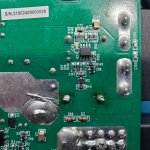
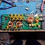
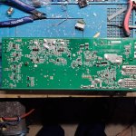
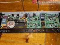
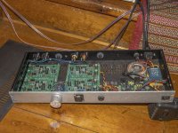
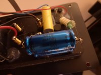
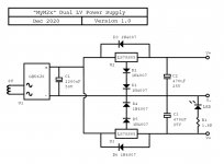
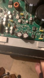
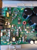
After a house move, a pair of very old (SN 2086/7) Quad ESL63s are buzzing, humming and hissing more than I remember - and enough to stop me using them and find some answers. After a bit of research on possible causes (and in the hope that it was only electronics to blame) my first port of call was replacing caps and diodes in the EHT unit and the 1000µF 16V PS cap on the protection board.

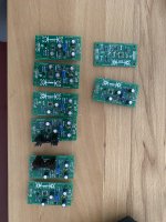
Unfortunately, this made no apparent difference and so the most likely (and most feared) cause was now rearing its head - that I have the dreaded 'stator separating from matrix' problem. Stripping them down to the bare panels has confirmed this. So I now have two options: delivering them to a professional service to renovate the panels or having a go myself. The first is easier, far more expensive and potentially means me being without them for a long time. The second is cheaper, a lot more personally satisfying but also quite a challenge/learning curve. I say that as someone who in my 20s worked for both Rogers as QA on BBC monitors and designer of the Studio 1a, and then later as a senior engineer at KEF with the privilege of working on advanced loudspeakers with such pioneers as Laurie Fincham and Richard Small. So I'm not afraid of electroacoustics, soldering or circuit diagrams! Unfortunately, KEF went the same way as Quad but did so first i.e. bought out by a Chinese company that was more interested in the brand name than the R&D brains and so squandered a considerable talent pool and focused on marketing and moving as much production as possible to China to save money. 🙁

First of all, a couple of apologies. This is quite a long post and covers ground that has been discussed before. In particular I have read a number of detailed threads here (e.g. this monster ESL Diaphragm coating). The reason I think it's relevant are:

0.1) I'm sure details have changed over the years as people here gained more experience with important issues like adhesives and membrane coatings

and

0.2) many others who are in the the same position as me would I'm sure like to have the key 'difficult' renovation issues all collected in one place.

So here goes with what I think are the toughest things to get right:


1) Choice of adhesives

What we want is something that:

- lasts a long time, in many realistic use cases (> 10 years?)
- is not too toxic to work with
- is relatively easy to apply
- is relatively easy to get hold of and not too expensive (in the UK or EU hopefully)

And there are 3 places where it needs to be used, only the first 2 of which seem to widely discussed.

1.1) stator to matrix

1.2) membrane to matrix

1.3) nylon damping to stator

In my case, (1.3) is relevant as several of the panels have the nylon damping material peeling away from the stator and this obviously needs to be addressed carefully.

I have seen several adhesives discussed:

- polyurethane
- contact adhesive
- epoxy
- super glue/cyanoacrylate
- others?

I would like to canvas opinion here from those with experience and expertise about which adhesives (with brand names or type numbers if possible please) have stood the test of time and satisfy what I believe are the key requirements in each case. It would be nice to use something that can be removed without too much grief when the next renovation is required - this would tend to downgrade epoxy and possibly cyanoacrylate also.


2) Acquiring, stretching and appropriately tensioning the membrane


Most seem to recommend a Mylar or PET membrance of 3-6 microns in thickness. This is not easy to find in the UK or EU without buying in bulk or paying what seems like a very inflated price for small quantities from specialists. Best links I have so far (they both do 3 & 6 micron):

Electrostatic Speaker Membrane Dupont Mylar C 6um 20M | eBay

Winkel - ESL Plus

By the way, do people think the extra mass of 6 micron has too much penalty (i.e. earlier high frequency rolloff) for the extra strength and easier handling?

Once I have this, it needs to be stretched on a jig or frame of some kind. I have seen some talk of a pneumatic arrangement though I have not been able to find details of this. I believe that some heat treatment can also be beneficial with either a hair dryer or heat gun, but it's not clear whether this should be before or after it has been attached to the matrix and stator.

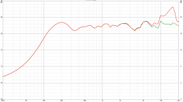
Then, how does one ensure that it is at the correct tension? I have heard talk of methods with coins, tension gauges and microphones. The only good panel I have disassembled so far had a fundamental resonance at 31-34Hz depending on how you tapped the matrix, with a strongish second peak at about 71Hz. Is this normal or has the unit stretched over the years? I have seen talk of 70-72Hz being the required resonance but I'm not sure if that is the acoustic resonance of the bare unit or the combined electro-acoustic resonance in circuit. I have both coins(!) and a good measuring microphone/system so reliable methods using one or both of those that match the original Quad spec are sought after.


3) Applying the conductive surface to the diaphragm

I have read a LOT about this, and many different opinions, including the mega-thread mentioned above which I finished at about 4am this morning!

To repeat my thoughts for requirements from the adhesives section. "What we want is something that:

- lasts a long time, in many realistic use cases (> 10 years?)
- is not too toxic to work with
- is relatively easy to apply
- is relatively easy to get hold of and not too expensive(in the UK or EU hopefully)"

I guess an extra couple of considerations here are "how well does it bond with the mylar without any surface finishing treatment?" and "how consistent is it over realistic temperature and humidity variations?"

There seems to be a number of options:

3.1) PVA adhesive with graphite powder or black ink

3.2) Commercial anti-static electronics products such as Licron Crystal, ACL Staticide 6300/6500, Statclear A50, others?

3.3) ESL-specific products from enthusiasts/specialists (e.g. EC/HTEC-coating from MJ Dikstra here, the coatings from ER audio in Perth Australia, Shackman in Germany, others?).

3.4) Weird and wonderful ideas like nylon fishing line melted in toxic solvents, anti-static floor polish, Turtle Wax F21, others?


I like the simplicity, cheapness and availability of (3.1) but there are some concerns about it being hygroscopic and perhaps therefore not lasting very well. Any brand names for recommended adhesives or inks are welcomed. Perhaps some PVAs are better than others in this respect? For example:

500ml PVA BOND ADHESIVE AND SEALER PRIMER & BONDING AGENT PLASTER CEMENT TIMBER 5060021361653 | eBay

and

Liquiwire™ 100 conductive graphite shielding paint paste glue ink pen | eBay.

I already have graphite powder. Was this the original Quad method? It seems to have lasted well on my units although the measured resistances given below vary widely across the membranes.

I'm happy to explore something in (3.2) as long as it's available in sensible quantities and not too expensive. I have read some concerns about how long Staticide stays conductive.

Also happy to go down the path of (3.3) and in fact am considering buying the entire renovation kit from ER audio. Any particular recommendations and if so with price and availability?

I like options in (3.4) if they are proven and not too toxic to work with. But for instance, how long do floor or car polishes stick and stay conductive on a thin mylar membrane with 5kV across it vibrating at 10kHz?

Then once you have the right thing, you have to apply it. There seems to be some consensus here that a foam pad or roller works well, possibly after diluting the coating medium with water or alcohol as appropriate.

There is an entire debate about how high the resistance should be, with the higher the better in terms of charge migration/distortion up to the point where it takes too long to charge up and/or other very high resistance paths start to enter the picture. My own simple measurements in (apparent) MOhms taken with a basic multimeter that measures up to 20MOhms and 2x 2 pence coins sitting on the original Quad membranes produce widely varying values:

With the coin edges 2mm apart
============================
Bass panel: 3.3 - 7.3
MF panel: 2.7 - >20

With the coin edges 25mm apart
============================
Bass panel: 7.2 - 18
MF panel: 8.2 - >20

I doubt if these are accurate results but they at least give me something to aim for, presumably a bit higher would be good so that I can just about read something near 20MOhms with coins 2mm apart. Interestingly, I could not get any measurements <20 MOhms on the reverse side of the membranes so that suggests that they are not a uniform layer.


Please feel free to send links to discussions on diyAudio or elsewhere on the web if they address any of the questions that I have asked here with definitive answers, and thanks very much in advance for having had the patience to read all the way down to here!

I hope this thread becomes a useful resource for others in my position, of whom I'm sure there are many.

Happy to be emailed/CC'd directly if you would like to: hop333 A T gmail D O T com

TIA

Michael

Clone a Soldano SLO100

Hi
I am about to build a Soldano SLO100 replica. I have everything, but the layout. My main issue is about the ground. This is a high gain dual channel amplifier, and if I start to mess around with the ground.

Usually, this is what I do

- Ground star 1: very close to the power plug to connect the ground cable
- Ground star 2: close to the input jack. From there I connect a bare cable that goes all the way on top of the POT. Every single ground from the preamp is connected there
- Ground star 3: close to the Power Supply. I put another bare cable that goes from the power supply to the power amp. Here I connect the power amp ground, Power Supply ground and center taps
- I also use blinded cables for the signals coming from the Input Jack and Master Volume.

So far, this works properly in every amp that I made (from 5W to 50W mostly with clean tone and some effects like Reverb and Tremolo). I got a super low hum, and everyone is happy with the tone.

The thing is that after reading the article that I attached about Grounding, I realized that I might introduced some ground loops in my circuit.

So I would like to know if anyone has some pictures from the layout of a real Soldano. I think this would be the best reference to take

Thank everyone

Attachments

FS: Dayton Reference HF RSS315HF-4 12" subwoofer drivers quad

SOLDSOLD my lightly used in good condition Dayton RSS315HF-4 12" subwoofer drivers.

asking $300 if you come and pick up all four , $160 for the pair, located in Madison Wisconsin 53704 .

i am willing to ship if you cover shipping and paypal fees .

Product Details Brand Dayton Audio Model RSS315HF-4 Part Number 295-464 UPC 844632006937 Unit of Measure Each Weight 25 Product Specifications Nominal Diameter 12" Moving Mass Of Diaphragm (Mmd) 188 Power Handling (RMS) 400 Watts Power Handling (MAX) 800 Watts Impedance 4Ω Frequency Response 23 to 1,000Hz Sensitivity 90.3dB 2.83V/1m Voice Coil Diameter 2.5" Thiele-Small Parameters Resonant Frequency (Fs) 24.2Hz DC Resistance (Re) 3.1Ω Voice Coil Inductance (Le) 0.96mH Mechanical Q (Qms) 2.83 Electromagnetic Q (Qes) 0.45 Total Q (Qts) 0.39 Compliance Equivalent Volume (Vas) 2.97ft³ Mechanical Compliance of Suspension (Cms) 0.23mm/N BL Product (BL) 13.99T·m Maximum Linear Excursion (Xmax) 14.3mm Surface Area of Cone (Sd) 514.7cm² Materials of Construction Cone Material Aluminum Surround Material Rubber Voice Coil Wire Material Copper Voice Coil Former Aluminum Basket / Frame Material Steel Magnet Material Ferrite Mounting Information Overall Outside Diameter 12.36" Baffle Cutout Diameter 11.1" Depth 5.75" # Mounting Holes 8 Optimum Cabinet Size (determined using BassBox 6 Pro High Fidelity suggestion) Sealed Volume 0.71ft³ Sealed F3 53Hz Vented Volume 2.05ft³ Vented F3 30Hz

GEDC5609.JPG

GEDC5617.JPG

GEDC5618.JPG

GEDC5614.JPG

Revox E36 - hum and impulse interferences in one channel only ...

Hi friends,
i am restoring Revox E36 (half track 9/19) for my friend. I have a problem with some disturbing (it looks like some impulse interferences and hum) in the signal. But in one channel only ... second channel is without interfering noises ... there is only a little hum.

What can be a source of mentioned interfering sounds?
Exist possibility, that tube(s) ECC83 could be a source ?

Thanks for ideas ...

Regards Peter

VOX VT20 Valvetronix footswitch problems

Hello everybody! I'm having problems with my amp-switch communication(VOXVT20+). The Footswitch lights up(was tested on another vox amp and it works) but it does not change Banks or Channels on the amp. I made few schematics but can't seem to find where the problem is ://. Any advice is welcome! Greetings from Croatia!
An externally hosted image should be here but it was not working when we last tested it.

An externally hosted image should be here but it was not working when we last tested it.

An externally hosted image should be here but it was not working when we last tested it.

An externally hosted image should be here but it was not working when we last tested it.

An externally hosted image should be here but it was not working when we last tested it.

Looking to pay someone to build a balanced Twin-T notch

I'm looking to obtain a balanced 1khz notch filter for the purpose of measurements. I have a good ADC and obtaining a 1khz notch for SE seems simple, but finding either a "matched pair" of SE notches, or buying a balanced notch, seeming isn't an option.

I understand this is a somewhat simple design, but the truth is I do not have the DIY knowledge or practice to build this, and I know that attempting to do so would likely end up with much frustration in trying to tune the notch properly and replacing components. (My soldering skills are nonexistant)

Therefore I'd like to ask if there might be someone here (ideally in the UK or EU) who may be able to build one for me. And how much you may want for the labour to do so.

Doesn't need to be anything crazy fancy, just XLR in/out, with matching notch frequency and depth for both poles. Ideally with as high Q as is possible/realistic.

If anyone here might be able to do this please do let me know! Thanks! :

Naim XTPS (Xtreme PSU) with High Performance Regulator(Europe only)

Hi,

I will order a little batch boards primary for Naim CD Player / Streamer (ND5 XSS, NDX, NDX2...) and DAC.


Facts:
- 280x400mm PCB
- 2mm thick, 2 OZ Cu
- 6+1 Rail (2 balanced rails, 2 unbalanced and one extra unbalanced for an extend output)
- each Rail 3.3-45V / 1-1,5A
- HF, DC transormer primary blocker with VDR´s
- Active Rectifiers based on LT4320 and MOSFET´s
- Common Mode Choke´s at transformer secundary
- optional CRC Snubber
- CRC (20.000µF) at main rails
- Cap Multiplier with BDW93/94C
- Stacked Regulators inspired by Jung/Didden Super Regs with some enhancements (trimpot to adjust output voltage, option for TL431 Voltage Ref...)


The board price depends on the number of pieces.
I think around 80€ for the Mainboard and 8-10€ for each Regulator-Board.

The Regs are tested.

See attachements


ToDo:
- complete shematic
- test layout
- write bom

Attachments

  • Naim XTPS.pdf
    Naim XTPS.pdf
    167.4 KB · Views: 336
  • SuperRegs.jpg
    SuperRegs.jpg
    871.9 KB · Views: 701

Eaton powerware NPR24 communications Rectifier info needed please.

Hello,
I have many NPR24 hot swappable rectifiers which were used in RF communication centres. These plug into a magazine and run in parallel to provide large currents for comms gear such as paging and LTE Transmitters.
Not Audio related however, these Switching power supplies are exceptionally well built and utilise ZVS topology as well as Power factor correction to minimise interference. The control uses a Atmel Mega32L and communicates using RS-485 modbus link (I think) communicates between the SM60 supervisory controller.

The NPR series where made back in 2007 by Powerware now bought out by Eaton.
I’ve contracted Eaton a few times regarding technical info, schematic and the modbus register map and as expected, got blown off. Can’t give information as its propitiatory line. Shame!
I feel there’s life left in these old girls and I’m finding plenty of used ones coming up on the web for not much at all. I’d like to save them from land fill or going to green waste and reverse engineering how to talk to them.

Question is, is there anyone with information about these such as register map for the modbus and schematic.

Somebody out there probably repairs them in early days.
Please PM if you can help out. Pictures attached

Cheers

Attachments

  • 90C904A7-B192-4CB6-AB1A-D7262B8542FB.jpeg
    90C904A7-B192-4CB6-AB1A-D7262B8542FB.jpeg
    106.3 KB · Views: 72
  • 75B2B86D-0C66-41A2-A833-880C10ABE3C2.jpeg
    75B2B86D-0C66-41A2-A833-880C10ABE3C2.jpeg
    160.7 KB · Views: 90
  • 20EDD704-2388-4ADB-99C9-2D1F002EF5BF.jpeg
    20EDD704-2388-4ADB-99C9-2D1F002EF5BF.jpeg
    201.9 KB · Views: 100
  • BAE9A186-3976-4970-B7EA-71990ABBE3B4.jpeg
    BAE9A186-3976-4970-B7EA-71990ABBE3B4.jpeg
    182.6 KB · Views: 76

FS: diyparadise USB Monica 2 with Black Gate N output caps

Hello

I'm selling a diyparadise Monica 2 USB DAC, it is almost new, because I went to a DAC with the bigger brother of the TDA1545A, the TDA1541A. So the great sounding Monica was used only a few times.
Except for the separated power inputs for TDA1545 circuitry and the Rudolf Broertjes' SS I/V Gain Stage, no modifications were done. The LM317 has already installed a heat sink, so it is ready for 18 Volt DC. This mod can be easily undone by reinstalling a diode into L3.(Yes a diode and not an inductor or ferrite bead) A lot of useful information can be found here:
Monica does USB!

Of course Monica still has the Black Gate N output capacitors​


Special OFFER 70 Euro, as it is really in great condition


Special OFFER If you buy the USB Monica for 70 Euro, you get the diyparadise usb converter, that I also offer in the swap meet, for free!

New international shipping rates:
Within the EU it will cost 7,39 Euro with tracking insured up to 50 Euro
To most countries it will cost 12,89 Euro including tracking and insurance up to 50 Euro​


I'm also open to trade against other diy stuff (ready made modules, kits, bare pcb's) and genuine audio transistors, regardless of they are small signal or power versions.

IMG_3165.jpg

IMG_3175.jpg

IMG_3176.jpg

I will ship worldwide. Further down you will find some examples. If you have other wishes or ideas for other, maybe cheaper shipping methods, I'm open to all proposals.

Within Germany it will be 4,99 Euro insured up to 500 Euro with tracking

Within the EU it will cost 7,39 Euro with tracking insured up to 50 Euro

To the most other countries it will be approximately 12,89 Euro including tracking and insurance up to 50 Euro

Of course I only charge the real shipping costs that I have to pay to the post office.

Payment by PayPal for friends and family, to avoid the fees from this greedy company.

Kind Regards

Phil

Upgrading crossover on Volent VL-2 Paragon

I am thinking about upgrading the crossover components in my Volent VL-2 Paragon speakers, and at the same time I would like to lower the treble with around 3 dB.

I am considering replacing all caps with Jantzen Superior Z-cap and all resistors with Jentzen Superes, but I am open for suggestions. And I guess that 10W 220 ohm resistor (see picture) might be hard to find as a better resistor.

And what should I do about those red/black bi-polar caps?

I know my way around soldering, but designing/altering crossovers is above my paygrade, so I would appreciate some help.

Attachments

  • Volent VL2 Paragon both sides.jpg
    Volent VL2 Paragon both sides.jpg
    373.3 KB · Views: 206

2 way: Upward firing 12inch + CD with 15inch waveguid

Hello,

I have been reading about Horns and wanted to start designing my first pair.
I see that most match the woofer size to the horn for constant directivity. I have been studying Earl Geddes designs and looking at best size compromise.

Because of design constraints I was wondering if I could use a 12inch driver pointed to the ceiling and cross over at 700 to 900 hz to a CD with a 15 inch waveguide. I would assume that I would lose low end directivity and that my directivity would start around when the CD takes over. Since I would be crossing over low would I have problems with this design?

I am planning to use a mini dsp for the crossover.

THanks for any help.

Why is this heater elevation circuit not working?

*Please forgive me for posting this in the Tubes/Valves forum, but seemed a more appropriate place than Digital Line Level considering the subject matter.

I've hit a snag with my current project and am hoping someone here might point me in the right direction. The project is a major reworking of my ANK DAC 2.1, consisting of a new power supply section for the DAC board and redesigned circuit boards for the power & analog output sections. The only parts left from the original kit are the DAC board itself and the main transformer & choke.

ctdKwVB.jpg


Sadly I am neither an engineer nor DIYer with years of experience; just a hobbyist who likes to bite off more than he can chew.

All of the new power supply boards are working as intended, however I have struck an issue upon connecting the B+ and filament PS boards to the tube output board. The output board is very similar to the version in the original DAC, but has been altered to accommodate the 5670 tube type instead of the 6DJ8 (I had been using the Russian 6N3P with an adapter previously). The other significant change was the addition of a heater elevation circuit, and it is this which is not operating as expected.

The new ANK M2x power supply has been split into two redesigned boards, one for B+ and one for the 5670/6N3P filaments. When connected to the output board the B+ supply works fine but the 6N3P heater supply fails to produce 6.3 volts. The filament negative (zero volt) is elevated to 62V as predicted, but the positive also reads 62V, rather than 68.3V as I would have thought. It's quite obvious just looking at the tubes that the heaters are not functioning.

When I disconnected the elevation circuit the heaters and their power supply started to function normally. The heater supply is not independent - it utilises a single winding on the same transformer that the B+ supply is connected to, along with a single rectifier and filter cap that feeds two 7805 regulators. So I'm wondering if I've made a mess of the elevation circuit on the PCB itself, or if there's an issue with the power supply configuration that means it's unable to be used in this way?

Or something else of course...

Attached are my modified ANK schematics and the PCB design for the 5670 analog output board.

Attachments

  • new-ank-output-board-elevated.jpg
    new-ank-output-board-elevated.jpg
    118.6 KB · Views: 562
  • new-ank-m2x-filament.jpg
    new-ank-m2x-filament.jpg
    75.5 KB · Views: 525
  • ank-output-board-new-elevated-traces.jpg
    ank-output-board-new-elevated-traces.jpg
    324.5 KB · Views: 501

Sonarworks XREF20 unreliable calibration file

I want to ask Sonarworks XREF20 users.


When I'm designing speakers for flat response with XREF20 then my speakers have harsh sound with too much treble. I have to correct crossover by lowering treble but then frequency response looks odd, with lowered treble area. Recently I've borrowed miniDSP UMIK-1 microphone with calibration file and repeated measurements. And suddenly everything was clear. Look at the attached picture. Green line is speaker designed with XREF20 for flat amplitude and red is the same speaker measured with UMIK-1. So calibration file for my XREF20 is incorrect. I've asked Sonarworks for explaining. Maybe it's possible they make mistake during uploading calibration file for my mic? We will see.


Sonarworks XREF20 users. Do you have good measurements results using this microphone?

Attachments

  • Sonarworks korekcja.png
    Sonarworks korekcja.png
    37.4 KB · Views: 531

Subwoofer decision

Hi all, this is my first post and I could use some help. I'm looking to build some subwoofer cabinets and I'm trying to figure out what is the most efficient box to build. I have built many cabinets in the past but that was a long time ago. I was looking at some of the Bill Fitzmaurice designs like the T-48 but my concern is being able to corner load them or use a V plate or any of the things that make them extend down lower. In my area clubs don't give you a lot of options as to where you can put your pa system. I like the idea of horn loading but I still want to get lower freq without building a box the size of a refrigerator.

I was looking to build a box like the old Carvin TRX 2-18" sub: https://cdn.shopify.com/s/files/1/0476/5297/files/TRx2218b_data_sheet.pdf?545461390985538386

my concern there is needing to feed the cabinet a ton of power to get what I want out of it.

I hear that Jbell came up with a partial horn design and there is also a box called a THAM that shows promise but I don't know enough about either one to make a decision.

I hoping that someone here has actually heard or used some of these cabinets and can comment or can recommend something even better.

I'm an Eminence speaker dealer so I would prefer to use them as I can get a better price on them. But I'm not ruling out going with another speaker if that's going to be better.

what do you suggest?

Portable boombox with local audio file playback

I was looking for a boombox to listen to music while sitting outside on my patio and rear courtyard. I'm a little exhausted from DIY efforts over the past few years, so I decided just to buy a commercial product. But here's the first stumbling block: most commercial boomboxes, or Bluetooth speakers as they're more often referred to now, sound terrible! I mean "terrible" not just from the viewpoint of a hifi elitist, but terrible as in turn-it-off-it's-hurting-my-ears! Then I read an online review which said that Audio Pro is the Bluetooth speaker for people who don't like Bluetooth speakers! That sounds like me. So on a whim I bought an Audio Pro Addon C5 in the last Black Friday sales.
Addon C5 - Audio Pro

This device, like its competitors, is mainly aimed at being a music streaming endpoint, but I'm old-school and I wish to play my own local music files through it. No problem, it has a line-in connection. So what device should I use for playback - an iPod, a smartphone? No, I decided to be "clever" and set up a Raspberry Pi with hat-DAC. But first I thought I should check the line-in function, so I connected the Audio Pro C5 to my home music server and ES9018 DAC.
Oh dear, the sound is a little muddy, and clearly inferior compared to the same music track streamed from Spotify. What gives?
I boldly opened up the C5, to discover it contains a WiiMu (aka LinkPlay) A29 streaming receiver module, connected (no doubt via I2S) to a digital amplifier chip - a NeoFidelity NTP-8230. The analogue input, then, obviously requires conversion to digital, and I can see this is via a TI PCM1863 ADC chip. I don't wish to malign the PCM1863 chip, but to my ears the NTP-8230 amp sounds obviously better with a digital input.

OK, so forget line-in, there's another option for local file playback: the C5's streaming receiver includes a DLNA endpoint. I tested this function by installing a DLNA server application on my Synology NAS box. DLNA streaming to the C5 works great, but with this current setup I can only play my local music collection when I am within wifi range of my home network.
Mmm, will I ever want to take this portable device away from home? Possibly. So ideally I should buy, or build, a small DLNA server device with internal storage, and attach it to the boombox. Extensive Google searches revealed no such commercial device. (I wasted money buying some products which were close, but not right). Looks like I will need to DIY. Sigh.
The Raspberry Pi is the go-to device for consideration here, but there are other single board computers which have better specs, and are smaller. I eventually chose the NanoPi NEO3 board, and for storage, a 480GB M.2 flash memory stick. I installed both of these in a metal case just 110mm X 75 x 30. It was a tight fit - the flash memory sits above the NEO3, and even then I had to cut away a section of the M.2 carrier board to avoid fouling the NEO3's USB3 socket.
The USB dongle at the top of the photo is a wifi adapter. The USB cable at the bottom is 5V power input. The red button is to initiate a GPIO trigger, to launch a script for a clean software shutdown.


Finally I mounted the completed DLNA server to the rear of the Audio Pro boombox, along with an AC power switch and 5V power supply. A short ethernet cable connects the server to boombox.


Now all I need is a DLNA controller app - BubbleUPnP - on my tablet, which instructs the server what tracks to stream, and instructs the boombox to render that stream.


So was this exercise worthwhile? 99% of the time I use this device in my home courtyard, within range of my wifi, so it would have been much easier just to stream from the NAS on my home network. If you need local file playback in a truly portable situation, the effort would be more justified.

Ampli Victor A-X5D

Hi everybody,
I have a problem with an old Victor A-X5D amplifier. My power circuit is getting very hot the power transistor and loudspeaker is muffled. I suspect 2 IC VC 5022 (Class A) is damaged which distorts the working mode of the transistors on the power circuit. Since IC VC5022 is not available for replacement, I want to skip Class A mode and run Class AB straight but I don't know how to do it correctly. I have attached a schematic and hope someone knows and has dealt with this problem, please just help.
Best regards,

Attachments

  • Screenshot (2).png
    Screenshot (2).png
    654 KB · Views: 366

81000d schematic

Perry Babin or anyone familiar, I thought the boards for the 1501d n 8100d were the same? I’m getting both sent to me I can fix the 1501 but he says the 81000d has different smd resistor than the 1501. He said the lil cap by the pre amp op on left keeps blowing. What would cause this? Any idea before I have to attack everything? Help please n thanks!! That’s the 1501 board I have but it’s the left cap blows as soon as it powers up. And he replaced all the fets power supply n output. I figured it has to be a bad smd resistor right before the cap

Attachments

  • BCFB5FC5-69CB-4D7A-BBF8-935DEC4767FA.jpeg
    BCFB5FC5-69CB-4D7A-BBF8-935DEC4767FA.jpeg
    449.9 KB · Views: 95

Mtx 1501d bad resistor

If anyone can tell me what this bad 100 ohm resistor is that goes to the fet in the middle of the board? Perry Babin I’d love ur input. U said that the fet doesn’t do anything for the amp vocal. Can u tell me what it’s for? And what the blown resistor does? The amp does seem to play fine. But I want it fixed.

Attachments

  • EC7F1601-D6CD-4605-924B-4566C1AD93EE.jpeg
    EC7F1601-D6CD-4605-924B-4566C1AD93EE.jpeg
    737.4 KB · Views: 78

best way to connect sub

I have a Mirage S12 subwoofer but I feel I'm not getting much hard hitting bass out of it. The whole house is shaking and all that but lacking in hard hitting bass.It's connected with by lfe at the moment.Should I be using the speaker level inputs on the sub instead?The manual specifies that I should be using either one but not both connections at the same time.
Has anyone experience in connecting powered subwoofer with LFE and speaker level connections?What is the best way?Can anyone enlighten me pls?
TIA!

2SK82 -2SJ28 SE Amp

I built a 2SJ28 L'Amp back in 2017 and I have been enjoying it very much in my bi-amped system since then. Thank you, Michael Rothacher, and also for the Luminaria, which I also built. The L'Amp is choke loaded with Hammond 193Vs and also has Hammond chokes in the dual CLC power supply. Add all this up, it is heavy, weighing in at about 60 lbs (27 kg). Alas, I'm finding that I can barely lift it safely; something had to be done. So, I figured the Hammond 193V chokes had to go. They weigh about 9 lbs or 4.1 kgs each and removing them would make a big difference.

My initial plan was a simple one - replace the chokes with current sources. I would use the existing 2 x 18V power transformer windings in series to produce a single 45VDC power supply instead of the existing 2 x 23VDC supplies. This would slim down the L'Amp to a manageable weight, and I would be able to move it occaisionaly to dust under it.

I then fired up LTSpice to explore how this all could come about. One thing lead to another, and I came up with this design which I built. It is a 2SJ28 source follower with a CCS load. The 2SJ28 is driven by a choke loaded 2SK82. So, trade a huge inductor for a small one.

Being the frugal type, I bought two Hammond 156C inductors for the 2SK82 load. They are cheap and some people have used them in tube amps with good results. They are only good for about 7mA of current though, so there is a downside to them. But they are cheap!

I managed to re-use the power transformer and the CLC filters. The transformer windings are connected in series to a single bridge rectifier and then to separate CLC filter stages for each channel. The 2SK82 has its own transformer and separate CRC filters for each channel.

The voltage amp stages are fed 175V and the self biased 2SK82s are operating at 122Vds and -25.5Vgs with 8mA current. You can see the FFT for 2,5Vpeak and 20Vpeak out.

The CCS for the 2SJ28 is supplied with 46V. Its output is connected to the 2SJ28 source. The 2SJ28's gate is biased by a voltage divider connected to the 46V supply. No need for a separate bias power supply.

I ran FFT measurements to confirm the performance of the choke loaded 2SK82 voltage amp. They are shown below. The FFT measurements for the complete amp are also shown below.

Overall, I am pleased with the results. Aside from LTSpice simulations, I did not know how well this would work. I was worried about hum pickup by the Hammond 156C inductors in the voltage amp. No noticeable hum, so I am happy. And also, the amp now weighs 46 lbs(21 kg). I can handle that.

I have just put the amp in my main system and I will listen to it for awhile before commenting on its sound.

Attachments

  • 2SK82-2SJ28schematic.jpg
    2SK82-2SJ28schematic.jpg
    169.8 KB · Views: 1,478
  • VFETamp.jpg
    VFETamp.jpg
    116.5 KB · Views: 1,452
  • 2SK82-2SK28-1.JPG
    2SK82-2SK28-1.JPG
    481.4 KB · Views: 1,180
  • 2SK82-2SK28-2.JPG
    2SK82-2SK28-2.JPG
    662 KB · Views: 1,197
  • 2SK82-2SK28-3.JPG
    2SK82-2SK28-3.JPG
    725.3 KB · Views: 1,160
  • 2SK82-2_2.5Vpeak-1.jpg
    2SK82-2_2.5Vpeak-1.jpg
    122.1 KB · Views: 524
  • 2SK82-2_20Vpeak-1.jpg
    2SK82-2_20Vpeak-1.jpg
    122.4 KB · Views: 373
  • Right 4V peak.jpg
    Right 4V peak.jpg
    124.2 KB · Views: 333
  • Right 12V peak.jpg
    Right 12V peak.jpg
    126.7 KB · Views: 352
  • 12VpeakSine.png
    12VpeakSine.png
    36.4 KB · Views: 572

Plate Inductors in Unity Coupled Output Stage

I'm trying to get a handle on the exact purpose of the plate inductors (usually ~2.2uH) in McIntosh amps.

It seems like these might help isolate the output tubes from output transformer capacitance at high frequencies without causing the resistive losses that a resistor would (like you would see used on the output of an op-amp).

I've recently experienced instability due to the capacitive loading the output transformer itself imposes in a high-feedback SE experimental amp. Putting a few ferrite beads between the feedback circuit and the output transformer cured the problem very well.

I have a Unity-Coupled amp of my own design that has no feedback around the output transformer. I have noticed fleeting signs of instability at times (low level, short duration oscillations on certain waveforms).

I'm going to try adding ferrite beads and was wondering if I should just add in series with the anode like the McIntosh amps, or maybe one to the anode and the cathode? Or maybe it doesn't matter because it is all in series? I'm just having trouble visualizing the best way to do this and what the consequences of doing it one way over the other might be.

FS: OPPO BDP-83SE Factory Special Edition. OPPO Serviced and Under Warranty

Selling my OPPO Digital BDP-83SE Special Edition audiophile Blu ray/DVD/CD/SACD player. Original owner from a smoke-free, pet-free home.

Just serviced by OPPO in Menlo Park (documentation included) and under OPPO warranty

Voltage: 100-240V

Cosmetic Description: 8/10 Excellent used condition with minimal visible cosmetic wear including some small marks on the top right and around HDMI input connector. This unit looks like new from just a few feet away. You'll have to examine very closely to find any signs of wear.

What is Included: Player, Remote, Manual, Carrying bag, double factory box and power cable, service/warranty paperwork.

Price $495 + shipping from Dallas TX


Horn 3-way Crossover Help JBL 2405h + DH1a

Hi everyone. I need a little help with a project I've been working on. It's a 3-way design and im trying to get the flattest filter possible and adding an L-Pad at the end. I have been experimenting with many different crossovers and slopes and havent seem to have gotten the right sound yet.

High-Frequency driver is a JBL 2405 8 ohm.

Mid-Frequency driver is an Electro-Voice DH1amt 16 ohm on a 1.4" Eminence horn.

Low-Frequency is a Dayton Audio RSS390HF-4

I know the low-frequency driver is not ideal, but Id still like to at least make something work and get a different driver in the future. I have taken a few measurements and will post them below.

FS: CUE-838

A pair of gorgeous JAN CUE-838. I have no idea what to expect for these. I see fantasy prices on ebay, but I don't really like ebay...

These were in a military wooden box which has been sitting in storage since WW2. The box and paper wrappings were pretty rotten, so now they are wrapped in fresh paper.

I do not know their condition. The getter looks good, pretty generous amounts of getter. The plates on one of them is slightly darker than the other, perhaps indicating some use...? See pictures.

The filaments look good and draw the correct amount of power.

Datasheets here: TDSL Tube data [838]

Please try me with an offer. Will consider trade with a pair of good FR drivers (preferably > 6") and/or some decent OPT (shipping cost may become an issue so we'd have to work something out).

Located in Norway.
Thanks

Attachments

  • 1479_1.jpg
    1479_1.jpg
    222.4 KB · Views: 119
  • 2454_1.jpg
    2454_1.jpg
    225 KB · Views: 117
  • 20210405_210645.jpg
    20210405_210645.jpg
    482.3 KB · Views: 122
  • 20210405_210701.jpg
    20210405_210701.jpg
    203.5 KB · Views: 109
  • 20210405_210737.jpg
    20210405_210737.jpg
    219.5 KB · Views: 109
  • 20210405_210758.jpg
    20210405_210758.jpg
    309.2 KB · Views: 69
  • 20210405_210917.jpg
    20210405_210917.jpg
    701.2 KB · Views: 58
  • 20210405_210935.jpg
    20210405_210935.jpg
    645.3 KB · Views: 59
  • 20210405_210855.jpg
    20210405_210855.jpg
    446.1 KB · Views: 57
  • 1479_3.jpg
    1479_3.jpg
    129.5 KB · Views: 64

Magnet interaction with mmc20en

As some of you might know i start building a tonearm especially for this cartridge i have from a disabled beogram 2202.During my trials i found that i could use a magnet for helping me attach the cart to the arm . At first i tried a small disk 3.5/ mm diameter magnet and then i wanted to try some more powerfull one , made out of two magnets from a dvd optical pickup, almost the same size as the back cut of the cartridge and 5 mm thick .
Given the internal geometry of MMC carts which is not entirely clear to me, but looks almost like it has a magnet placed at the back, how would you think my external magnet placed at the back of the cartridge be affecting the cart's specs? I tried to get an answer on this on beoworld site, but it looks like nobody's tuned into my curiosity...Most probably what we see at the back of the cart isn't the cart's magnet so if it's the metal closing the magnetic circuit, my magnets won't be able to interact with the cart's magnet field, but even if it does how will it do it?Will it decrease the cart's magnet field or increase it?
Unfortunately i am not allowed for the moment to upload any images on the site...I have no idea why.

Alpair Pensil 10p Build - and Questions

This is my second speaker build. My first was a set of Dallas II cabs I documented here :

https://www.diyaudio.com/forums/full-range/318518-dallas-ii-build.html

My wife felt pretty strongly that she wanted something with a smaller footprint in the living room, so I'm building the Pensils and the Frugel Horn XL and seeing which ones get the upvote. I'm going to have fun with it.

This promises to be an easier build, but as a trade-off, I plan on being more detail-oriented with this one. I broke down the stock over the weekend into roughly what all the panels will need to be (pics later).

In order to make the speaker as adjustable as possible, I'd like to be able to easily remove the driver and the back panel - and in the interest of durability, I was thinking of using machine screws/bolts and threaded inserts directly into the wood. These usually come in some kind of metal. For the back, I'll use some kind of neoprene along the edge to seal it up and avoid vibration. The driver gasket will do the same thing along the front. Are there any issues acoustically with using these metal inserts?

Second - I've decided for now to forgo the side to side bracing, which the designer says are not needed for the (smaller than 12p) pensils. Anyone have thoughts?

Third - I'm considering a double thickness baffle for the front, but the trade-off is that with double 19mm plywood, I either end up with a deeper inset (which I guess I can chamfer) or I end up with a lot of thickness behind the driver frame (which I can also chamfer). Any pros or cons here?

Looking for help repairing PPI PC450

Hello,

I recently installed my old PC450 amplifier into a new car. I had this amplifier for years with no issues.

In the new car I immediately noticed the amp got very hot and stopped outputting. I did not have an inline fuse installed.

I powered up with a current limited supply and found the output transistors were getting very hot. I removed them from the board and checked for shorts but found none. I replaced anyway and still have the same problem with new fets.

The amplifier powers up normal drawing normal current then after about 30 seconds it draws max current limit from the supply (5A) and all outputs get hot for all 4 channels.

Currently only the outputs for CH1 are on the board and the problem still occurs.

Any help would be greatly appreciated!😀

Help biasing Pioneer SA-8500II Phono stage

I installed new transistors in the AWF-023 Equalizer Amplifier board on the Pioneer SA8500II amp. I used the KSA992s and KSC1845s. The voltages on Q9 and Q10 are off a little and I wasn't sure if I need to change any of the bias resistor values? Also the current is at 4.1ma instead of 3.5ma. Not sure if it's off enough to matter? I have all the voltages marked on the schematic. Sorry the schematic is a little light.

Kennyg

Attachments

  • 20210403_120951.jpg
    20210403_120951.jpg
    411 KB · Views: 108

Best speaker kit for smallish living room? (13x9x8)

Hey everyone,

Long time lurker here. Always blown away by the wonderful builds you all post!

I'm looking to build another set of speakers to celebrate a career milestone. However, a lot of the science-y stuff I've read is a bit over my head. I hear all sorts of different (and great) insights here on builds and I was wondering if anyone could guide me a bit better in my research toward my next set of speakers. 🙂

This is more of a speaker question than a room acoustic question: Unfortunately, I'm pretty tight on space (see pics) so paneling, while I know makes good kits into amazing kits, isn't really an option as far as I've seen.

Current Setup: AviaTrix MTM powered by an SMSL SA-98E (160 watt x 2) amplifier. Source is a HiFiBerry DAC+.
What I'm Looking For: Honestly, I absolutely love the sound of these speakers! I only really wish they had a bit more bass. So merely remedying this is an option as well 🙂

Room Size: ~13'x9'x8' LWH
Room Details: Next to kitchen (left) and large window (right). Only (audiophile) upstairs neighbor; no walls shared with any neighbors
Speaker Distance from Listener: ~13'
Budget: ~$2000* (not including amplifier)
Build Preferences: Premade or pre-cut cabinets / full kits. I can veneer, though I'm not averse to pre-finished / repurposed cabinets
Tools: Electronics workstation (Hakko digital soldering iron). No woodworking tools nor experience past veneering and maker places in my city are indefinitely shut due to Covid 🙁

*Price is flexible; by no means does it reflect what I need to spend, just an upper limit of what I'm comfortable spending. Lower priced kits absolutely are encouraged 🙂

Pictures of room (with dimensions) here:
Imgur: The magic of the Internet

Any help would be greatly appreciated. Thanks in advance 🙂

Philco 9200 tube tester always indicates cathode shorts

I love the aesthetics and build quality of my Philco 9200 tube tester.
It's a fine example of functional industrial art IMO. It's so steampunk it has a scroll, not that it is any different from any other tube tester. At the hart of the tester is a transformer with 18 different secondary taps!

Anyway, I made the mistake of spraying the switches and tube contacts with Deoxit. It now indicates filament leakage no matter what tube I put in. I hypothesize there's some current leakage going on due to pools of deoxit at tube socket sites.

Is this a feasible explanation?
I assume Deoxit conducts electricity to a degree?

If I could isolate the tube sockets completely I'd stand a better chance of chasing down the leakage. Unfortunately, there is no switch position that does that. Impedance back through the transformer secondary's makes this a Thevenin parallel path nightmare with the power off so it's difficult to obtain any useful info using an ohm meter.

I think I might just remove the scroll and submerge the entire circuitry in a pan of alcohol, swish around, let dry, and retest. it's virtually impossible to get even a q-tip between socket pins with all the wiring present.

I thoroughly understand the circuit now. I've made neon bulb voltage measurements during the tests which line up with what I am seeing.

Any other suggestions?

Attachments

FS: some miro1360 DAC AD1862 PCBs

Hi folks,

got some PCBs for miro1360's DAC AD1862.
I ordered more than I need, so I have 8 pieces left.
newest PCB version: diyAudio_AD1862_DAC_v1.3_pad_PPY3_2021-01-14

Price for each is 2,50€.

I try to keep shipping costs as low as possible:

Germany: 1 PCB 0,95€, >1 PCBs 1,55€ unregistered
for registered mail please add 2,20€

World: 1 PCB 1,70€, >1 PCBs 3,15€ unregistered
for registered mail please add 3,50€

hurry up now 🙂

Greetings,
Ralf

Attachments

  • IMG_20210324_162630.jpg
    IMG_20210324_162630.jpg
    430.9 KB · Views: 217
  • IMG_20210324_162700.jpg
    IMG_20210324_162700.jpg
    258.4 KB · Views: 210
  • IMG_20210324_162901.jpg
    IMG_20210324_162901.jpg
    604.1 KB · Views: 202
Projects by fanatics, for fanatics
Get answers and advice for everyone wanting to learn the art of audio.
Join the Community
507,781
Members
7,888,170
Messages

Filter

Forum Statistics

Threads
406,224
Messages
7,888,170
Members
507,781
Latest member
Ronny2001