I am thinking about upgrading the crossover components in my Volent VL-2 Paragon speakers, and at the same time I would like to lower the treble with around 3 dB.
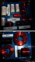
I am considering replacing all caps with Jantzen Superior Z-cap and all resistors with Jentzen Superes, but I am open for suggestions. And I guess that 10W 220 ohm resistor (see picture) might be hard to find as a better resistor.
And what should I do about those red/black bi-polar caps?
I know my way around soldering, but designing/altering crossovers is above my paygrade, so I would appreciate some help.
Attachments
Helo
is it necessary to replace ALL caps and resistors ?
I would start with those in the direct signal path.
Normaly there is no such 220hm resistor in a signal path ...
Is there any information on the x-over-design ?
is it necessary to replace ALL caps and resistors ?
I would start with those in the direct signal path.
Normaly there is no such 220hm resistor in a signal path ...
Is there any information on the x-over-design ?
I don't know anything about the crossover design except the crossover point is 1800Hz.
I am thinking that since I have to open up speakers and remove the crossover plate I might as well fix it as good as possible but maybe with the exception of the 220 ohm resistor (or maybe switch that as well to something new but cheap like a Jantzen 20W Ceramic resistor which exists in 220 Ohm version for about 1$)
I think the connection between the crossover and drivers are solid silver vires, if so I will replace them with OCC copper vires instead (they are a little to forward).
The whole thing looks really good (and fresh) to my eyes. The norm is to not even touch things that are work OK. However, since you've opened up the box, it's better to do the following:
* Check thoroughly if anything (including the PCB) is burnt/charred. If yes, change only the burnt item with another of the "same kind".
* Trace and prepare the circuit diagram for the network (if you don't have it already).
* Measure the electrolytic caps if possible. If you don't like the electrolytic caps you may change them to poly (lower ESR).
* Keep any parts you change, just in case you want them back for some reason.
* You may also retouch any dry solder joints for better reliability.
Note: Silver is a better conductor of electricity when compared to copper. If you have silver wires, I suggest you leave them alone.
Last edited:
Dear MagnusHH,
Well then it's electrolytic to polypropylene that you can try. That would improve capacitor lifetime significantly (at least).
Note: It's the drivers that largely govern sound quality and changing network parts only fixes a network-induced problem, in the absence of which the speaker is going to sound just the same, even after all your efforts.
All the best.
I'd be inclined to encourage MagnusHH to play with some EQ, see if you can identify areas for improvement. Perhaps do some measurements.
I've mostly found drivers to be quite similar once properly selected and set up in a given role.It's the drivers that largely govern sound quality
And playing around with EQ would require addition (and/or removal) of parts to/from the existing network and not just "replacing all caps with Jantzen Superior Z-cap and all resistors with Jentzen Superes", as originally intended.
A circuit diagram for the existing network needs to be traced out, before trying any of the above.I don't know anything about the crossover design except the crossover point is 1800Hz.
Last edited:
Perhaps a misunderstanding newvirus?
I meant an equaliser, either an app or a box with sliders or dials.
I meant an equaliser, either an app or a box with sliders or dials.
I'd be inclined to encourage MagnusHH to play with some EQ, see if you can identify areas for improvement. Perhaps do some measurements.
I would agree... do some measurements, identify areas for improvement, target them with EQ (this can be done in software on PC at no cost). Measure again to ensure the EQ had the intended effect... then listen! Take notes, what has changed... is it better to your ear? If you can do EQ adjustments in realtime from your listening position, all the better. You will learn a great deal about what contributes what to the character of your speaker & it's interaction with your room very quickly this way.
Once you've done the initial learning, you can start honing in on specific areas to improve with EQ, and listen longer term to those adjustments. Once you settle on what you like, you can implement either as permanent active EQ, or adjust passive XO to mimic what you've done, or at least address the most problematic areas.
I meant an equaliser, either an app or a box with sliders or dials.
Well, that is entirely up to the OP to try. My earlier response was based on the information in the first post where the OP says that the treble needs to fall by 3dB and wants the crossover network to do it for him/her.
I've mostly found drivers to be quite similar once properly selected and set up in a given role.
Regarding the above, I have no comments to make, as it is a highly subjective topic.
Peace.
It can be, when you consider the different ways some people use them. In any case there are still many things that go into making a good driver.
I am using DSP for room correction (REW + rePhase). And i also have good room treatment in place (bass traps + absorbers for first reflexes and lots of diffusers). Lots of other tweaks as well (dedicated power, only air insulation OCC copper cables etc).
This idea of upgrading crossover components will not give a big boost but maybe it can give a little like a little improved soundstage.
This idea of upgrading crossover components will not give a big boost but maybe it can give a little like a little improved soundstage.
About lowering treble: I always seems to get best sound from DSP when doing as little as possible. Especially higher frequency seems very sensitive. So if possible i like to leave everything above 500Hz untouched.
Altering some resistor should be able to lower the treble but not sure which resistor or amount to raise or lower
Altering some resistor should be able to lower the treble but not sure which resistor or amount to raise or lower
The crossover is already of high quality. I believe the speakers are only around 10 years old, so the bipolar electrolytics will be in good condition and, anyway, their position in the circuit will not seriously compromise the sound....designing/altering crossovers is above my paygrade...
I really don't see the need to change the existing components.
However, if you wish to lower the tweeter level, you could experiment by placing a resistor in the positive wire going to the tweeter.
Assuming a tweeter impedance of 6 ohm (matching the system impedance), a 2.2 ohm,10W ceramic resistor would give around 3dB of attenuation.
If you find this value of series resistor to give a satisfactory degree of attenuation, we can then design a constant impedance L pad attenuator which will do the same job, but with more finesse.
This would be the best approach, but we'd better see a crossover schematic first.Altering some resistor should be able to lower the treble but not sure which resistor or amount to raise or lower
I don't have any schematics, do you have a qualified guess based on pictures? Resistors (even good ones) are cheap so I can experiment and try if needed. I also have measuring microphone and REWThis would be the best approach, but we'd better see a crossover schematic first.
Hello
You the original x-overs. So it should be possible to look how all parts are connected....
You the original x-overs. So it should be possible to look how all parts are connected....
We would have to be able to trace the circuit in order to identify the function of each of the resistors in the treble section.
Given the complexity of the circuit, It would be difficult to do this from photographs, even if we could see the reverse side of the tweeter board.
The value of the resistor at top left in the photograph is obscured. Can you read it?
We would have to be careful not to upset that true ribbon tweeter!
You the original x-overs. So it should be possible to look how all parts are connected....
Yes, it's the OP who has physical access to the network and therefore he/she is the one who is best positioned to trace the circuit diagram.
- Home
- Loudspeakers
- Multi-Way
- Upgrading crossover on Volent VL-2 Paragon