Maybe a somewhat uninformed comment...but could an L-pad be inserted before or after the resistors in the tweeter circuit?
Before i order components i will open them and check all values carefully, and then i can also split the plates and check wiring.
Although if i get a little softer sounding components i can probably skip the lowering of treble and use same values as original components.
Although if i get a little softer sounding components i can probably skip the lowering of treble and use same values as original components.
Yes, a variable L-Pad could be an interesting tool here especially for smaller changes where the crossover is at fault. However if it is not, what about using EQ to bring the balance of tone into line with the room?Maybe a somewhat uninformed comment...but could an L-pad be inserted before or after the resistors in the tweeter circuit?
220 Ohm???
That is probably 22.0 Ohms; just a first guess. I looked at the tweeter specs, best I could tell anyway by reading up on this model and the LCY standard line of tweeters with the ability to play down to 1800 Hz or so. I'm thinking 3rd or maybe even 4th order X/Os here; there are a lot of parts for just one woofer and one tweeter per side! A sketch of a wiring or connection diagram would be very useful, full schematics even better as many others have already said....
Helo
is it necessary to replace ALL caps and resistors ?
I would start with those in the direct signal path.
Normaly there is no such 220hm resistor in a signal path ...
Is there any information on the x-over-design ?
That is probably 22.0 Ohms; just a first guess. I looked at the tweeter specs, best I could tell anyway by reading up on this model and the LCY standard line of tweeters with the ability to play down to 1800 Hz or so. I'm thinking 3rd or maybe even 4th order X/Os here; there are a lot of parts for just one woofer and one tweeter per side! A sketch of a wiring or connection diagram would be very useful, full schematics even better as many others have already said....
LCY-110S | Twin Ribbon Tweeter 雙鋁帶高音 | SPEAKER DRIVERS 喇叭單元 | LCY | BRANDS | Ying Tai Audio - 應泰音響
LCY-130S | Twin Ribbon Tweeter 雙鋁帶高音 | SPEAKER DRIVERS 喇叭單元 | LCY | BRANDS | Ying Tai Audio - 應泰音響
If the tweeter is from the standard LCY line then most likely one of these.
Using the handy dandy attenuator calculator; if we assume 6 Ohms and want -2 dB; the resistors in the L-Pad circuit would be about 1.3 Ohms and 22 Ohms (approximately)...other values of course very possible; just a quick calc and quick guesses ONLY...
I looked at the notch filter calculators also. A 220 Ohm resistor in a parallel notch that one would place in series with a woofer would give about 35 dB or more of attenuation. That seems extremely excessive so 220 Ohms is most likely really 22.0 Ohms. I have used high value resistors in parallel with inductors on a woofer or mid LP filter to raise the higher frequencies slightly; usually no more than 68 or 82 Ohms and much more like 8 to 33 Ohms (typical).
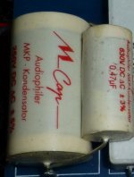
Based on the pictures (I will remove crossover plates and check more careful later), the following caps are used (per speaker):
Mundorf MCap MKP Classic
2 * 4.7 uF 250V MPK
1 * 2.2 uF 250V MPK
1 * 18 uF 250V MPK
1 * 0,47 uF 630V MPK
The last two in parallell (note the difference voltages?)
Other caps
1 * 0.68 uF 250V polypropylene film capacitor
1 * 27 uF 100V bipolar electrolyte
1 * 4.7 uF 100V bipolar electrolyte
1 * 18uF 250B MKP
1 * 47uF 100v bipolar electrolyte
And that 220 Ohm resistor really does look like its 220 and not 22.0, see attachment. But to make sure I will measure later on.
Attachments
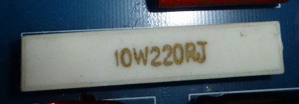
Yep, sure "looks" like 220 Ohms in the photo. Lift at least one lead so it is out of the circuit before you try to measure it since we don't know it's real purpose or how it is connected in the circuit (at least not yet anyway!). It would be REALLY helpful to all of us if you could do a point by point connection sketch of some kind. At the very least; disconnect the drivers (making sure to note polarity of wires to +/- driver terminals, etc FIRST!). Then, at least the woofer VC and ribbon xformer won't be in circuit.
Anyone know of a reason for the different voltages in the 2 caps in parallel?
Capacitors in parallel reduce the effects of ESR and ESL, giving a closer to ideal impedance curve for the combination. The different voltage ratings do not matter, as already mentioned above by Galu.

My reasoning for the choice of caps are like this:
- The current Mundorf caps likely are for the treble, so replace them with something very good but not too expensive.
- The rest of the caps are probably for the woofer, so upgrade them but keep the cost down.
I also (for some non-scientific reason) like to keep to one brand 🙂
- The current Mundorf caps likely are for the treble, so replace them with something very good but not too expensive.
- The rest of the caps are probably for the woofer, so upgrade them but keep the cost down.
I also (for some non-scientific reason) like to keep to one brand 🙂
OK, just to be very clear here... I have been doing speakers OVER 50 years! I studied acoustics under the very best minds on the planet. I really do NOT care if you believe me or not! I always am right and I know everything by some of the brightest acoustics and engineering guys in the known universe... make you your own conclusions...my knowledge of acoustics saved the planet and prevented WWIII...STOP arguing with me! I studied under the best minds on the PLANET!!!
Hi
These white Mundorf were availble in 250, 400 and 630Volt.
the higher voltage-series sound a little better....
You know about the cap-test by Toni Gee ? Humble Homemade Hifi - Cap Test
click on the graph for his fast rating - on page 2 you finde the three Mundorfs... In the text-version you will finde more explanation on each cap.
Take a look at te Mundorf MCa Evo-Öil in the text version.
this Evo mixes well with Jantzen "red" - e.g. the 18µF-cap could be done by mixing 10µF Evo-Oil plus 8,2µF Jantzen "red"- this will save a little money.
In the smaller values as e.g 4,7µF I would go for a single Jantzen.
it looks like a bypass.Anyone know of a reason for the different voltages in the 2 caps in parallel? See attachment
These white Mundorf were availble in 250, 400 and 630Volt.
the higher voltage-series sound a little better....
You know about the cap-test by Toni Gee ? Humble Homemade Hifi - Cap Test
click on the graph for his fast rating - on page 2 you finde the three Mundorfs... In the text-version you will finde more explanation on each cap.
Take a look at te Mundorf MCa Evo-Öil in the text version.
this Evo mixes well with Jantzen "red" - e.g. the 18µF-cap could be done by mixing 10µF Evo-Oil plus 8,2µF Jantzen "red"- this will save a little money.
In the smaller values as e.g 4,7µF I would go for a single Jantzen.
Last edited:
Oh yes, I have studied that Humble list. I am also considering Mundorf MCap Supreme MKP for its slightly warmer tone (which my system would like since its a little to forward right now).
Or maybe the Obbligato aluminium-foil MKP.
Having said that, I hate to lose to much details 🙂
Or maybe the Obbligato aluminium-foil MKP.
Having said that, I hate to lose to much details 🙂
- Home
- Loudspeakers
- Multi-Way
- Upgrading crossover on Volent VL-2 Paragon