Mono outdoor upgrade

I am looking to make some upgrades the outdoor music system I had made a few years back. Currently I have echo dots setup around my property which send their audio to each other and one dot then sends the audio via 3.5mm cable back to an Sony amp running in mono mode. The amp then goes to a volume switch controlling each zone. I bought some new speakers which are capable of 300 watts / channel which is well above the 100 watt output of the sony amp. I also do not think the Sony amp is doing a great job at sending out mono audio. While I am upgrading I was debating changing the 3.5mm audio to a wifi and or Bluetooth receiver and changing the sony receiver to a more powerful one and maybe a biamp nexia cs for the mono audio control. I would also need a speaker switch that can handle the extra wattage and was looking at few by OSD. Currently I am thinking along the lines of Echo dots to bluetooth/wifi receiver to Biamp nexia CS to Amp to OSD. Is there anyway to combine some of these things into one device without getting a Sonos system?

audio research 100.2 trouble

Hi Guys,
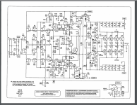
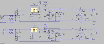
i have a ARC 100.2 in trouble here. The muting circuit is always on and the led flash. I have 0V in gate of Q47, 0.06V in base of Q41,42, -7V in gate of Q44 and 0.6v in pin2 of U3. I d'ont understand the utility of the circuit with the optocoupler RY3. Someone can help me?

I found this schema on the net

Maxpou

Attachments

  • audio research 100.2 protect.png
    audio research 100.2 protect.png
    300.4 KB · Views: 133
  • audio research 100.2 amp.png
    audio research 100.2 amp.png
    505.6 KB · Views: 129

Adapting polyurethane adhesives for panel speaker applications

Hi all

I like the idea of polyurethane adhesives (e.g. Gorilla glue) for a number of tasks on panel speakers, but I would like it to be thinner sometimes (for applying) and to foam less or hardly at all.

I have read on another thread that acetone is an effective thinner, perhaps 1:1. Does it affect bond strength or foaming?

How about other relatively benign things: water, alcohol, lighter fluid? I'm not a chemist so if any of these are really stupid ideas then my apologies!

M

The Further Adventures of the 6p3p Kit - 12AT7 Driver Mod

Greetings, Friends. I've seen several older threads on this amplifier, but none seemed to touch on this mod, so Here Tis: I've reworked the 6p3p DIY amplifier kit available from a variety of online resellers to use Western tubes.
rLGAfBb.jpg


The original kit came with a pair of 6p3p power tubes, a 6n1 driver, and a 5z4p rectifier, or in my case the Soviet 5Ц4C. Here's the schematic that comes with the kit
1uvlszA.jpg


I found an older thread on this site dealing with this kit, and an improved design was produced by user Raindance. I've taken his pretty drawing and made 2 changes: by swapping the cathode resistors on the driver tube to 470R, we can use a 12AT7 as the driver tube. And the power supply section as designed is a tad hungry, so I've replaced the 47u with a 18u and the 330u is then replaced with the 47u to keep the rectifier from working so hard. I also have a 5uF mylar cap as bypass on the 47uF, but that's not mandatory.

I currently have it set up with an old GE 5R4GB rectifier and new Ruby 6L6GC power tubes, with a Ruby HG 12AT7 Driver. Sounds Great.
Uu41RWH.jpg

Symmetric preamp PSU using 2 positive PSU

Hi,

Makes it any sense to build a symmetric preamp PSU using 2 positive PSU in series?

I've build a PSU using one positive and the complementary negative PSU. LM317 + LM337 & IRF510 + IRF9510 cap multiplier. Shunt regulator part is identical.
The issue here is that it needs a lot of tweaking to get output voltages within 100mV the same.

I know the 317 is better than de 337 part. But does the circuit as attached is really better than using a positive and a "real" negative PSU.

Attachments

  • Symm preamp PSU.JPG
    Symm preamp PSU.JPG
    110.6 KB · Views: 246

Second attempt at Building my own amp from scratch

Ive been reading this forum and have greatly enjoyed all the experience of the members here.

Here is my 2nd attempt this time I really want to learn.

Criteria is a 100W amp into 8Ohm, with acceptable performance,
I dont expect a great result as this is a first and very new to me.

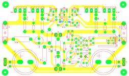
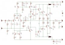
I wanted to keep it simple. I drew have 2 circuits,
Ive made a toner transfer pcb of the first circuit and will build it as
time allows.
The second circuit is just a thought, to be more flexible at various supply voltages.
Ive only spent about 2hrs on second circuit.

Pls inform of changes I should make.
Ive tried to do the best I can, but I need advice.

Attachments

  • 1.schematic.jpg
    1.schematic.jpg
    180.1 KB · Views: 1,474
  • 1.pcb.jpg
    1.pcb.jpg
    361.2 KB · Views: 1,400
  • 2.schematic.jpg
    2.schematic.jpg
    179.3 KB · Views: 1,352
  • 2.pcb.jpg
    2.pcb.jpg
    438.2 KB · Views: 1,289

Cambridge Audio P60 Repair

I'm working on a Cambridge Audio P60, which puts out a very loud buzz on all outputs, including headphones. Unfortunately it's a massive struggle to get anywhere, as the schematic available does not have a board diagram, and bizarrely my P60 does not have part labels on the board! So none of the components are named and therefore it is very difficult to know what is what according to the schematic.

Has anyone experience with working on one of these who could help me out?

Many thanks,
R.

Symasym - the next generation (supersym)

After many E-mails and even a few download attempts at my "supersym" PCB ( It's not done yet.. have patience :bigeyes: )
, I am starting a new thread to : 1. Share the existing amp (PCB and construction advice) , 2. Design a professional board that will maximize performance and fidelity. , and 3. develop it further with JFET inputs (anatech's suggestion)and a MOSFET OPS.

The design as it is now...
An externally hosted image should be here but it was not working when we last tested it.


It has been the best sounding by far of my DIYA creations.
It stays biased within 2mv , any environment , drives paralleled 15" 3-ways all day at full volume .. no turn-on thump , completely stable in every way. 😎

The base schematic is here ..
An externally hosted image should be here but it was not working when we last tested it.

I am using C21 as my HF compensation. I have a 470K in place
of c6/r13.
Attached is the LT file to see for yourself (all models included). Make sure the "supersym .txt" in the zip file is in the same directory as the .asc file (models)..
OS

Attachments

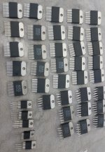
FS: OPA549S and OPA549T

I purchased these beauties long time ago from (I think mouser) made many good amps with these.

Recently while digging my old items found them, I don't think I have much use for them. They are as follows:

OPA549S (25)
OPA549T (10)

I intend to offload them at $10 a pop, shipping from my country through snail mail is $15, any one who buy 5 or more I 'll bear half the shipping cost myself.

Anyone buys 10 or more I'll throw in 2 OPA548 per 10 pieces, I only have 5 of them so first two gentlemen who buy 10 or more will be getting 2 OPA548 free.

Attachments

  • OPA549.jpg
    OPA549.jpg
    421.8 KB · Views: 116

Vibration at back of Swan M200 III's

Hello all, first post here so apologies if its in the wrong place.

I have a great pair of Swan M200 III's. There are no problems with the actual speaker cones themselves, but there seems to be a slight vibration around the region of the heat sink, at the back of the right speaker. This is apparent whether the speakers are quiet or loud, and only with certain frequencies.

For example, the beginning of this track Tango N' Vectif - YouTube

Loud bass or other higher frequencies, don't seem to trigger it. No cracking or distortion with the cones, or any other issues.

If anyone could advise how I could investigate and sort it out, that would be much appreciated. Thank you.

841 DHT Hybrid Headphone Amplifier

While working on an 801A A2 amplifier design, I experimented with using its high-mu cousin, the 841, in the voltage gain stage. Ultimately it did not work out, and so I have quite a few of these 841 tubes available, along with ready-to-go filament transformers and Rod Coleman's regulators. They are burning a hole in my pocket.

11242614.jpg

I am all SET on speakers amplifiers at the moment (see what I did there?), but I am in need of a quality headphone amplifier. It so happens I have a pair of Sowter 8665 headphone output transformers on order. I married the 841, Sowter 8665, and my desire to build a headphone amplifier into the design below.

841 Spud diyAudio.png

A couple of notes:

1) The 841 has a mu of ~25 when CCS loaded, from my measurements, and a plate impedance of roughly 25K, necessitating the buffer to drive the output. Here is the datasheet: https://tubedata.altanatubes.com.br/sheets/049/8/841.pdf

2) I've used SiC filament bias on the 841: 400Va / 5mA Ia / 3.25Vk bias point

3) The Sowter 8665 is "designed to be driven from a cathode follower output stage via a coupling capacitor", according to Sowter. I have seen these used before in "spud" parafeed designs most commonly. The transformers are rated for 500mW at 20Hz - as drawn the amplifier will put out ~400mW into a 32ohm load at maximum 1.8Vrms input signal, which would make me deaf. Here is the OPT datasheet: https://www.sowter.co.uk/pdf/8665.pdf

4) The Sowter 8665 has three primary windings that can be paralleled, I will likely include a switch to change from 12:1 to 4:1 turns ratio for higher impedance headphones (300ohm)

I recognize this design is somewhat silly with the high B+, impracticality of the 841, heat dissipation, etc., but that is the joy of diyAudio, building things because you can, not because you should 🙂 open to ideas, otherwise I will update here if and when it comes to life.
  • Like
Reactions: toshiba_nz

Help suggest diy headphone tube preamp/amp to build

I am interested in building a tube headphone preamp/amp for a friend. He currently uses a Topping A90. Can anyone suggest any that would be likely to impress his ears? I don't want to bother making something that won't compete with what he already has. He has never experienced tube amps. I have some experience with them regarding guitar amplifiers and I'd like to build something for him.

A kit would be ideal, but not a deal breaker.

I might also be willing to just buy one and not build it (although building it would be cool to keep down the cost and make the gift more special).

Thanks for any help you can offer. Feel free to ask questions to help narrow things down more. I can try to get any answers that could help.

Edit:
35 ohm headphones would be the main use and focus of this

Advice sought: Woofers for compact sealed boxes

I'd like to add a pair of subwoofers to the system described here. The bass, except for the bottom octave, is extremely satisfying as is. Acoustic bass is more convincing than I've heard from most conventional boxed speakers. But the 20-40 Hz requires a lot of cone excursion with open baffles, so I'm looking for suggestions for subwoofer drivers.

While the current system is optimized for music (my priority), I'd like to add to the home theater fun and reduce the risk of bottoming out the open baffle woofers when the T-rex footsteps arrive. It's only happened once or twice, but it makes me cringe. So I'd like to back off on the very-low frequency equalization on the open baffle woofer array, and make up (and then some) the bottom octave output with a pair of sealed box subwoofers.

I've already pushed the tolerance of my co-listener with the twin tower speakers, and more recently, the addition of sound absorbing panels behind the speakers. So I need subwoofers that are not visually intrusive: small but capable. I have zero interest in bragging about an extra 2 dB at 16 Hz, and I never listen at really high SPLs. But the speakers are at the end of a large great-room (about 20' x 60') so there's a lot of room to fill with sound.

I have two channels of ICEpower to drive the woofers (500 watts/channel into 8 ohms, 1 kW into 4 ohms). I've been eyeing the Sound Integrity SQL 12" and 15" woofers so far. They're currently offered at slightly reduced prices. They're described as working in 1 ft^3 and 2 ft^3 sealed boxes, respectively, although modeling shows them to start rolling off at pretty high frequencies in those boxes. I'm assuming they're intended to be used with lots of bass boost to get good response down to 20 Hz.

I'd like to avoid going any higher in price, if possible, and to keep the box volume low I'm aiming for sealed enclosures. Are there other drivers I should be considering? I haven't spent a lot of time learning what's out there in the subwoofer driver market.

Thanks in advance for any suggestions.

Few

DIY 12V Car audio power supply - troubles

Hello everyone!

I am building a switching power supply to be used in the CAR AUDIO field, feeding it from the wall network, obtaining an adjustable output voltage from 12.4v to 14.4v (and beyond).


I made a project from scratch.

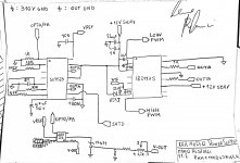
The power supply uses the SG3525 PWM controller which drives an IR2113S driver which in turn drives a pair of very powerful IGBTs.
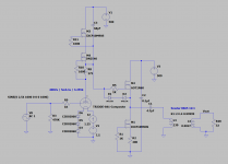
The power supply is regulated, and keeps its output stable even when we are absorbing almost all the deliverable current (or at least it should) and through a potentiometer that adjusts the reference of a TL431 which in turn drives the LED of an optocoupler, I get voltage regulation and setting.


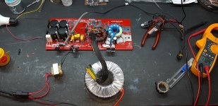
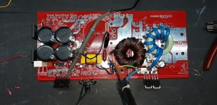
I made the PCB and installed the main components to start testing it, currently I have not installed the protections (short circuit and thermal) because I was interested in knowing if at least it did its primary job (produce enough voltage and current as I thought it would).

After doing everything, instead of immediately using the direct electrical network, I used a transformer to isolate myself from the electrical network and obtain a lower voltage to avoid disastrous failures, in fact, with 78Vdc on the large capacitors, everything was fine, the power supply produced the voltage desired, but obviously little current, in fact by loading the power supply with a 40w car bulb, the voltage dropped to 7 volts.
So, I used a bigger isolation transformer, and with 110Vdc on the big capacitors, still all right, and the voltage was also more stable, the current delivered, higher, and the voltage dropped a lot less (down to 10v).
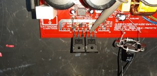
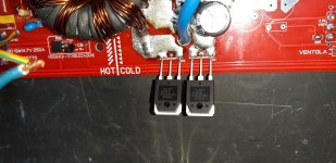
Everything seemed ok to me, there was no abnormal heating anywhere, so I switched to direct mains, first with a 220V - 40w incandescent bulb installed in place of the primary fuse and I got a lot more stability, but obviously when trying to absorb more current, the bulb started to light up and choked everything, then I replaced the bulb with a 47ohm 10w resistor, and I still got some improvements, then finally I decided to remove everything and install the fuse, now the problems started, because the power supply turned on without problems, but as soon as I connected the car bulb in output, one of the two internal diodes (of one of the 2 double power diodes) spontaneously shorted out suddenly, and having no protection systems I broke the two IGBTs and the driver accordingly.


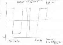
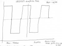
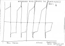
Cabbage! everything was going well, I would have also installed the protections and I could have fully tested my power supply, but something went wrong. Maybe the output filter? Perhaps the absence of Snubber on the output power diodes? It wasn't just a coincidence, because I fixed everything, and it happened again. I will post the schematic and some drawings of the waveforms that I saw on the oscilloscope before the failure, I have drawn them by hand, because it all happened yesterday, and I did not have the thought of taking pictures of the screen.


And of course, this is the videotest:
video

thanks to all,
Aids are appreciated!
Mario
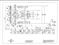
Attachments

  • 20210405_221931.jpg
    20210405_221931.jpg
    418.7 KB · Views: 109
  • 20210405_221943.jpg
    20210405_221943.jpg
    438.8 KB · Views: 110
  • 20210405_221949.jpg
    20210405_221949.jpg
    391.7 KB · Views: 108
  • 20210405_221955.jpg
    20210405_221955.jpg
    458.2 KB · Views: 104
  • power-transfer.jpg
    power-transfer.jpg
    449.4 KB · Views: 107
  • pwm-generator.jpg
    pwm-generator.jpg
    348.4 KB · Views: 84
  • sg3525-signals.jpg
    sg3525-signals.jpg
    175.1 KB · Views: 77
  • ir2113s-signals.jpg
    ir2113s-signals.jpg
    209.3 KB · Views: 56
  • output-signal-diodes.jpg
    output-signal-diodes.jpg
    219.3 KB · Views: 54

  • Locked
Building my own noninductive 8R 150W load using wire wound resistors

Does anybody have any tips or suggestions on how to create a noninductive load resistor (or low-inductance load resistor) using cheap 10W wirewound resistors in cement block packages?

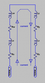
I am thinking I'll put N of them in parallel (reducing inductance by a factor of N) and then arrange the current paths to be in opposite directions. This will create a mutual inductance between adjacent resistors, and since the currents flow in opposite directions, the effective inductance will be reduced to (L - M) where L is the self inductance and M is the mutual inductance.

I just purchased qty=28 of 10 watt, 56 ohm resistors. I'll put 14 of them in parallel (giving a 4.0 ohm resistor), and connect that in series with another set of 14 ohms in parallel. End-to-end resistance is 8.0 ohms, and inductance is (hopefully) a lot less than (1/14th) the inductance of a single resistor.

Figure 1 below shows a schematic of my connection. Figure 2 illustrates the mutual inductance between a pair of adjacent resistors. Of course it's a distributed system but for compactness I've drawn it as two "lumps".

What do you think of the idea? Is there a far, far better way to get low end-to-end inductance when using wirewound resistors?

Thanks for reading!

_

Attachments

  • figure_1.png
    figure_1.png
    6.2 KB · Views: 1,438
  • figure_2.png
    figure_2.png
    10.7 KB · Views: 1,485

Bluetooth Kit to Connect B1 Korg to Amp Camp Mono Amps?

I have the B1 Korg and Amp Camp kits already, and I am part way through the amp build. I thought it would be nice to be able to place the amps remotely with some bookshelf speakers, and use bluetooth from the pre-amp to reach them individually. The benefit being that I would not have to route speaker wires around multiple doorways for the layout I am looking for. The only problem is that I have not been able to find a single kit that will do this. I have seen stuff at Best Buy and places like that for bluetooth-ing surround sound speakers, but I was hoping for something more on the kit level (plus I had a best buy kit for my sub and it was terrible). I would like each amp to get a dedicated receiver too. I could wire one or two transmitters, whichever would be available.

Has anyone ever done this before? Is there a kit or pieces I can put together to make one?

Thank you.

-Geoff

Chassis ground point on the pcb

Lets take a ss psu pcb, a ground plane arrangement for the smoothing caps then at the output a star ground for signal and power return. Should the chassis ground (back to back diode+ cap+ 10ohm) be terminated at the star ground or at the very end of the psu ground plane near the rectifiers?

I read a post here that it should be the latter because the chassis ground is very dirty and its basically there to flush out any standing current, but i cant find that post.

long tailed pair - need more gain

I'm building a push-pull amplifier with balanced inputs.
Right now the only gain stage is a long tailed pair (with current source)

It works, but I need more gain (and i'm already using high-mu triodes).
I could simply add another pair of triodes and a current source, but something tells me there is a better way. (involving less current sources and coupling capacitors)
I have been searching for such a schematic/topology/.. but havent found one.

Anybody knows such a thing?

New member introduction

Hello all,

I’m new here, having arrived at your place looking for advice regarding speaker building. I’m interested in building a pair of full range single driver towers and will post in that section soon. But first things first. I have a variety of gear, some interesting and some more mundane. I like nice vintage stuff and have some McIntosh, Marantz, Thorens, etc. but there’s also some new gear mixed in with it and over time it’s evolved into what I think is a pretty nice setup. But I’m ready to try building something and have already been doing a lot of reading and gathering of ideas. I’m looking forward to learning some new things.

Greg

Behringer x32 faders and encoders

Our X32 has 18 (to varying degrees) faulty faders and a faulty encoder. I have found a couple of sources for the faders:
Behringer Motor Fader MF100T (set of 5) | DV247 | en-GB
Behringer X32 Motor Fader – Thomann UK

but I'm struggling with sources for the encoder that have stock (at least in europe):
Behringer X32 Screen Encoder | Behringer X32 Parts – British Audio
this has Behringer Part Number: Y32-00000-19166 , I wonder if anyone knows where I can get hold of one? or of any equivalent part (as presumably not manufactured by Behringer).

Thanks!

variation in vent tuning frequency

I am interested in the variation in actual Helmholtz resonance frequency versus that which is predicted by theory.

I remember an article by Augspurger in SpeakerBuilder magazine in the 1990's, but I can't locate my copy (I thought I saved them all)...

Does anyone have data, or can point me toward some research, on the normal variation that might be expected.

Thanks !

jim

Class D Amp. Help with Schematics

Hi All,

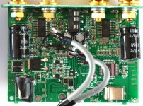
I have the attached Class D Amp that has no Data on it as to its Origins.
1)
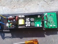
Front end is an ADAU1701 Dsp board with input and controls.
2)
The ADAU1701 has two outputs one for HF and one for LF
3) The attached photo has the ADAU1701 and the LF section.
4) The LF section is a Class D/SMPS Combi. and is housed in a 1200Watt Sub cabinet.
5) The HF unit is satelite.

The sub is used in a church environment and subsequently blew up the mains fuse and fried the LF speaker.
I need a schematic or help to identify this unit so that I can workout how to rectify, the fault.
Replacing the fuse and connecting through a bulb indicates all is well but there is a sort of "Phatting" sound out of the LF speaker with no input.

Thanx in advance for the help

Ike

Attachments

  • Pic 3@0,25x.jpg
    Pic 3@0,25x.jpg
    474.1 KB · Views: 157

New Electrocompaniet AW120 clone

This is what I have come up with. Design is largely based on AW120, except original protection circuitry, voltage amp power supply
and a small twist on input stage biasing.

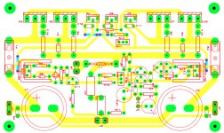
Would anyone care to comment on the pcb design, as it is getting toward completion? Left and right channel signal paths are mirrored except around the output transistors, where I have tried to keep respective trace lengths equal.
What would you do in a different way? Any other comments/ideas are welcomed.

Cheers.

Attachments

Drivers close to internal sidewall?

I don’t see much topic on this what’s the idea of having drivers butted up against a sidewall? Say the frame is truncated so the sidewall would be right of on the frame of the speaker. What does this do for sound?
Same with an internal divider for woofer/midrange if it’s right in between the truncated frames so the drivers are still close but there’s a wall dividing them. A lot of speakers I’ve bought have the drivers mounted very close to a sidewall or brace so I’m guessing it’s fine to do?

JLH 1969 Problem...

Hi, All,
Over twenty years ago, i built a JlH 1969 for my son using a couple of Heart Kits. For a cabinet I used a scrap Pub rack mounted amp box...
This amplifier is still going strong today.
Recently, I decided to build one for myself and bought a couple of chinese copies to speed things up. I fitted MJ15003's rather than the obviously old - used - 3055's.
The heatsinks are 4x RS Black 6x5".
The new build has worked fine for one night then today the left channel went distorted, getting worse and Q1 was boiling hot and Q2 very cool.
Q2's collector is at 2.5v and I cannot reset mid point voltage.
Current drain is still 1 amp as set by me initially...
Any help will be appreciated.
Kind Regards,
Michael

Abletec alc1000

Hoping for a little advice please folks.one of my alc 1000 modules decided to go bang.the fuse on the board was blown.i changed it and it also blew with a bang straight away.
I am a total novice and know next to nothing about the insides of these devices so just asking for some simple advice please.
My alc 1000 modules are coming up to about 10 years old and this is the first problem i have had.i took a look for any obvious damage apart from the fuse.the only thing that looked bad was a thermistor NTC 33 1012
It was almost crumbling and the writing had completely faded.
I am living abroad now and parts are difficult to get here but it is with a repair shop that have said 4 mosfets need replacing which they are trying to source.the numbers on the mosfet are k3934 8.a
I dont know what gets damaged first, the thermistor or mosfets.if the thermistor causes the damage and its just age/heat related should i change the thermistors on the other 4 modules that i am using before they blow.the writing has faded on 2 of them also.
Many thanks

Recommendations for 1/8"/3.5mm and 1/4"/6.35mm Stereo Jacks for PCB Mount (& KiCad)?

Recommendations for 1/8"/3.5mm and 1/4"/6.35mm Stereo Jacks for PCB Mount (& KiCad)?

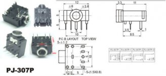
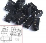
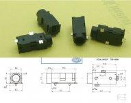
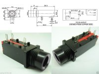
I am selecting PCB mount jacks (both 3.5mm & 6.35mm or 1/8" & 1/4" stereo) and I was wondering if I could ask for advice on which ones are recommended and long lasting. I thought I would ask before I stock up and make PCB designs with a bad jack design.

I am using KiCad so if there are existing tested footprints that would be great but otherwise I should be able to edit an existing footprint to support a different design.

The first three images are 3.5mm (1/8") stereo jacks that I have found online but I am not sure which are more reliable and long lasting. I wonder if the first one is strong and long lasting due to the metal sleeve connection that goes straight to a PCB through hole.


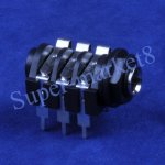
The fourth image is 6.35mm (1/4") and I think it might fit a Neutrik footprint that KiCad already has. I think it is a long lasting design as I have seen them inside my gear (such as in my Digidesign 003 rack and all still work fine).

The fifth image is also 6.35mm (1/4") and I also think it is a long lasting design since I have also seen see that design inside my gear. That last image does not appear to have a footprint in the standard KiCad libraries but they look like connectors for 2 of the channels in 15 year old E-MU 1616m interfaces that still work today without any crackling.


Any suggestions? Should I avoid any of the ones shown in the attached images? I will be using them with notch filters, LNA and DAC/ADC.

Attachments

  • 3.5mm PJ037.jpg
    3.5mm PJ037.jpg
    20.1 KB · Views: 600
  • 3.5mm PJ320.jpg
    3.5mm PJ320.jpg
    115.4 KB · Views: 248
  • 3.5mm PJ326.jpg
    3.5mm PJ326.jpg
    23.1 KB · Views: 170
  • 6.35mm Common Type.jpg
    6.35mm Common Type.jpg
    127.3 KB · Views: 168
  • 6.35mm Type Seen In EMU 1616m for Two Channels.jpg
    6.35mm Type Seen In EMU 1616m for Two Channels.jpg
    70 KB · Views: 209

No Power to SSE amp on first power up attempt

Hi All,

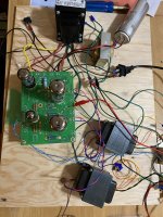
So this is my first electronics project and I am an absolute beginner with all this stuff. I have spent the last couple months putting together George's Simple SE. tried to start my checkout today by metering between R4 and ground. When I turned the power bar on nothing happened. No voltage reading, no light, no smoke. I have two ideas of what it might be besides the fact that I have no idea what I am doing.

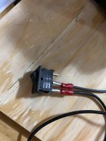
Firstly I purchased an on-on switch by accident. I may have wired this wrong. I wired the middle prong to the opt, and the bottom prong to the fused plug.

My other thought might be the empty sockets labeled D4, D3, and TR1. I saw in some other threads that these need diodes and a in-rush current limiter. Is that still the case?

Cheers,

Bassy

Attachments

  • Amp 1.jpg
    Amp 1.jpg
    813.8 KB · Views: 163
  • Amp 2.jpg
    Amp 2.jpg
    746.6 KB · Views: 157
  • Amp 3.jpg
    Amp 3.jpg
    547.3 KB · Views: 159

NAD 3125 blown fuses and output transistors

NAD 3125 Integrated Amplifier
This unit immediately blows 4A fuses F1 and F2 upon powerup.
Even with F1 and F2 blown I get some output, but extremely distorted.

Preamp circuit appears OK.

Main amp bridge rectifier pulled and tested OK.
Main amp large 4700uF 50V filter caps pulled and tested OK.
I disconnected output transistors Q110/Q210 and Q111/Q211

Now the fuses don't blow and I get clean +27V and -27V on the output power rails. Good!

I then pulled and tested all four output transistors (D1148R and B863R) and they appear OK. C to E is not shorted. Testing with the DMM on diode check mode and each transistor looks like a pair of diodes, just like one would expect for an NPN and PNP bipolar transistor.

I then pulled and tested another small transistor Q107/Q207 and they also appear OK. This transistor is mounted on the heatsink either for cooling or temperature compensation. I believe this transistor is part of the bias adjustment circuit.


I don't see any discolored or burnt components anywhere.

Any suggestions for what to check next?

I don't have the 3125 schematic but the 7125 appears to use the same circuit and reference designators.

https://www.vintageshifi.com/repertoire-pdf/pdf/telecharge.php?pdf=Nad-7125-Service-Manual.pdf

Pioneer SA-620 idle current / distortion issues

hi all, new guy & first post here, hoping to pick the collective Brain to help me with an issue im having with my pioneer sa620 🙂
I have a pioneer sa620 amp that I recapped about 12 months ago, and until 3 days ago has been purring along perfectly......it now has a low volume level distortion issue on the right channel only. so far (with no improvement) I have:
searched for cold/dry joints
removed and tested both main output transistors and they seem within spec and fine, replaced anyhow just, well, im home recovering from spinal surgery so hey, I got plenty of time and boredom to overcome lol, I've replaced every component in the bias circuit for the right channel, I've replaced every single diode and zener in the entire unit, every transistor in the amp & preamp circuits and also the power supply circuit I've also RE-RE capped the entire unit (yea yea don't judge, like I said im home for 6 weeks recovering, and I have plenty of time and spare parts / components to play with lol! but after all that still no improvement, the right channel low level distortion and zero idle current remains!
I will add that this issue is also present through headphones, and switching to MONO also makes no improvement or difference.
idle current on the left channel is sitting happily at around 25mv the right channel though is a flat zero 0.00mv

im no expert but an avid hobbyist who loves playing around with this stuff and im not afraid to give anything a go, I've searched and scanned the forums but unless im looking in the wrong spot I've not found anything of assistance. hoping the collective brain out there could steer me in some sort of direction. thanks in advance guys.

Pioneer SA-620 Stereo Integrated Amplifier Manual | HiFi Engine

Tube socket quesitons.. too loose?

Had my amp upside down for a day or three, now that mouser has come through via the big brown truck I figured time to pull the tubes and have at it.

I gently touch the 1st 300B and it almost fell out on its own! Glad I was slow and steady turning the amp over, it could have taken a dive on the cement floor... Im guessing that isnt ideal...

2nd 300B needed very little coaxing, but at least did'nt fall out..
There looks to be a little room where I might be able to squeeze the fingers together, probably safest to use two sets of needle nose so I dont stress the entire socket.. Should I attempt or am I asking for trouble and just replace the sockets ?

The 12AX7's were in very snug..
The RCA 6SN7's were snug but nothing near the 12AX7's.

2nd question, is there a way to quantify the force needed to insert/remove tubes and whats a good range ?

Last for this post, is it normal that the the back of the tube socket (where leads get soldered) wiggle a lot when removing the tubes ?

VTA PH16 Phono Pre Build

My First DIY
Vacuum Tube Audio PH16 Phono Preamp
I decided I wanted to start listening my vinyl again. I retipped my Denon DL103R, tuned up my VPI Scoutmaster turntable, and decided it was time for a new phono pre. I had an EAR 834P that I thought had quit on me (actually it was fine, just a bad tube), replaced it with a Parks Audio DSP but it did not do it for me. Seemed a little dry. Nice little unit, but I missed the tube stage. The desire to DIY took over. I decided on the VTA PH16 over a Bottlehead. Have not heard either, but the reviews were good and the experiences read in other posts were positive so off I went.
I bought a few supplies – Hakko Solder Station, Solder Sucker, Extech voltmeter, Cardas quad eutectic solder, wire stripper. Then I bought an Amazon 7th grade level practice kit. Glad I did. I had not soldered anything other than making cables. The pictures of my build show my skillset. Not great but improving.
Exchanged a few emails with Roy, and the kit showed up a few days later. I decided to go with the upgraded Mundorf caps and added a choke to the power board but everything else was stock. I had the case top and sides powder coated black and changed out the chassis screws to black. (not sure why as it sits in the middle of an equipment rack)
Kit was complete except was missing a little wire, but Roy had it in the mail promptly. The build manual is not a hold-your-hand manual but everything you need is in there. My lack of experience did shine through in a few spots. My first attempt to fire it up yielded nothing. I had a few diodes in backwards and had to turn a voltage regulator around. Fixed those but was getting some bizarre readings. Exchanged emails with Roy, I tried a few trouble shooting ideas but still could not get things right. I unhooked the boards and mailed them to Roy. He quickly determined I had a bad HV regulator. He replaced it and added a missing ground and he shipped them back next day. Hooked it all up same night and it was fine. Dead quiet. Even though I have always wanted tubes in my amplifications, I cannot stand hiss. There is none. I have a Altec 4722 SUT in front of the PH16 to allow for the Denon DL103R’s low output. I want to mention that working with Roy was great. Quick to respond to emails and send out supplies as needed.
I no longer have the EAR 834P so I cannot make any side-by-side comparisons, but I did not take a step back. The PH16 is everything the EAR 834P was and probably more. Plenty of body and soul. I have some NOS Amperex 6922 tubes I will roll in the near future.
Next DIY – Ordered an Elekit 8600S from Victor.

Attachments

  • P1020029_000.jpg
    P1020029_000.jpg
    220.7 KB · Views: 304
  • P1020030_000.jpg
    P1020030_000.jpg
    301.6 KB · Views: 301
  • P1020031_001.jpg
    P1020031_001.jpg
    130.5 KB · Views: 263

Mid 70's amp distorting pretty badly. High crazy base voltages 20v¿?

Hi. I got an old amp from the mid 70's that I'm trying to fix. The fuses were gone and so some tiny bulbs which illuminate the front. The switches need deep cleaning in order to get some sound of it.

The thing sounds and pots work ok, but it distorts very badly. At low volumes is ok, but it starts to distort pretty soon.

It uses a couple of BD131 and BD132 as output stage transistors. The voltages are odd. Here they are:

BD131 (NPN)
  1. 21v
  2. 32v
  3. 21v

BD132 (PNP)
  1. 21v
  2. 0v
  3. 20v

The amp is fed with 32v DC. It's a 2x12w at 8ohms.

My knowledge is quite limited, but assuming this is a class AB complementary amp, base voltages are crazy. And if I'm not wrong, we should be expecting a lower emitter voltage as well. Something around 16v.

There are a few resistors that are pretty hot. You can touch them for about two seconds, then it hurts. Couple of them are "tanned". They read the correct value, but you can see they suffered at some point. There's one of them that drops the voltage to 21v to 0.7v...

I replaced the output transistors and all electrolytic caps with no luck. Where should I be looking at? I'm lost

There's a trimmer right at the supply voltage. It's set so the voltage drops to around 19v. At max. it drops the voltage to 16v or so, no more.

There's obviously something very wrong. Transistors are biased at really high voltages. I can't understand what's causing such levels. It happens to both channels. Right now I'm focusing just in one of them since they behave the same.

There's no schematic so I'm going to make a sketch of output stage core. The core are the couple BD131 & BD132, a MC150 which feeds the BD131 and a SC107B. The latter is handling 32v at one of its legs...

I appreciate any help, thanks.

Speed control using low frequency phase correlation.

Given that a record has a cyclic low frequency wave(s) that are below the standard frequency used for audio. Could it be possible to use a low pass filter and then sample the low frequency using an ADC. Then use FFT phase correlation to essentially match the cycles of the record as they're playing and correct the speed of the record?

You're not sampling or correcting the record playback via digital but rather using the record noise to correlate (note that phase correlation has decent noise rejection).

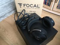
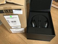
Focal Elear Headphones perfect condition

Maybe someone here would be interested, also on the bay but at good discount here for the DIY family 🙂

The very best headphones under £800 or more, I love these and is a reluctant sale but I have bought some Stax, so need the funds.

Absolutely perfect condition and working order, still under warranty, I am the second owner. These were bought 2020 and have been kept mint in a case when not used. Fully boxed and with original shipping carton.

Selling for £500 plus shipping

Attachments

  • IMG_2718.jpg
    IMG_2718.jpg
    978.1 KB · Views: 136
  • IMG_2722.jpg
    IMG_2722.jpg
    970.9 KB · Views: 128

Advice about sound cards please !

Hello guys, I hope I'm posting in the right place, it's the first time I write something on this forum.
I have a friend who would like to connect its UMC404HD to a pair of passive loudspeakers, wich are 2 Infinity Primus 150.
I've done some research and here's what I found :
connecting directely the passive loudspeaker to the main output (either XLR or 1/4" jacks) will work but will damage the sound card in the long run.
The solution is to use an amplifier between them.
I've chosen this one : AIYIMA A07 Amplifier Stereo Class D TPA3255 2x225W 4 Ohm - Audiophonics
Here's how I think of it :
I'll make him a cable wich goes from his jacks main outputs to the RCA of the amplifier (so I need to make 2 Jack-RCA mono cables) and I'll just make a regular loudspeaker cable from the amplifier to the loudspeakers.
What do you think ? Do you see any flaws ?
My main concern is I'm not sur about the main line output going into the RCA input of the amplifier.
Thanks in advance.

Fell lens

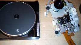
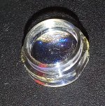
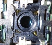
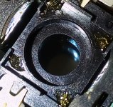
Hi guys.
My CD Recorder Pioneer stopped working.
After disassembled it, I found that the laser lens rolled into the box.
Obviously fallen during transport.
Is it possible to fix with glue or something more is needed?

Cheers

Attachments

  • DSC_12166---.jpg
    DSC_12166---.jpg
    780.6 KB · Views: 117
  • DSC_12146_cr.jpg
    DSC_12146_cr.jpg
    297.3 KB · Views: 105
  • DSC_12151_cr.jpg
    DSC_12151_cr.jpg
    371.8 KB · Views: 105
  • DSC_12154_cr.jpg
    DSC_12154_cr.jpg
    334.7 KB · Views: 126
  • DSC_12172_cr.jpg
    DSC_12172_cr.jpg
    305.1 KB · Views: 116

Troubleshooting a Dynaco ST-35

I was demoing some new-to-me speakers (8 ohm, not a difficult load) and was using my Dynaco ST-35. It was playing fine for awhile (10min?) and then the music stopped and I heard a hum and I turned off the amp. Smelled a little smoky smell.

I took out the amp, opened it up, inspected inside and couldn't see anything particularly wrong. So I put some dummy loads on the speaker outputs and turned it back on upside down so I could see if anything obvious was happening.

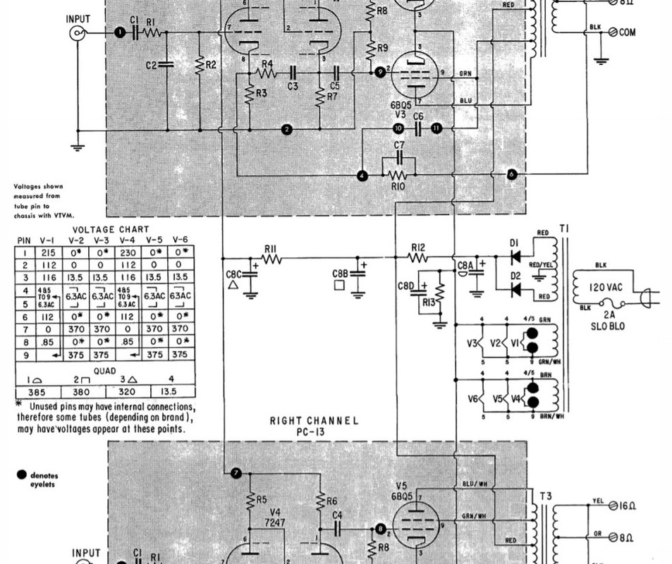
Turns out the 50ohm/5W (R12 in schematic) started smoking, so I quickly turned it off.

I measured the main power supply capacitances C8A, C8B, C8C, C8D. C8C and C8D measured as the implemented parts indicated. C8A and C8B measured significantly higher than expected. C8A should have been 40-60uF but measured about 160uF. C8B should have been 20-40uF but measured more like 260uF.

Came back a few hours later, and now C8A and C8B are both measuring about 80-90uF (still higher than expected, but lower than immediately after I powered down the amp).

Any idea why R12 would start smoking - I mean there must be very high current flow through there, but C8B wasn't shorted to ground or anything.

Haven't tested the tubes, output, or power transformers, but everything was working for 10min or so.

Just looking for suggestions on where I might start looking for problems given the symptoms.

Thanks.

ST-35-Schematic.jpg

Has anyone tried SEAS U16RCY?

Choosing the drivers for the next project is the most intriguing part of the diy procedure.
This time I am looking for something small and I want to try a seas driver since my previous attempts were with sb acoustics and I would like to try something else.
I've seen two nice projects from well respected designers in the diy community, the one is the seas curv by troels Gravesen and the other is the prestigious monitor from gornir from audio excite. Both are promising but I am not sure about the seas u16rcy. I've seen some measurements at audio excite and the u16rcy distortion is much worse than the sb15/sb17.
Should I stick with the sb acoustics or give it a shot with the u16rcy?
Has anyone worked or listened to u16rcy?

Beginner project: TA7630P + TDA1557q

Hi all! New member here.

I'm an electronic beginner, and as a first analog project (until now I played with arduino and similar) I wanted to make a simple chip amplifier with some controls.

I managed to find a TDA1557q and a TA7630P.

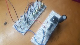
So, I breadboarded the TDA1557q sample circuit from the datasheet and the TA7630P sample circuit, also from datasheet (single power supply one).

The main problems are two:

1. When i plug my phone aux into the TA7630P circuit the output volume is really low, instead, when i plug the phone directly in the amplifier, is much higher. I read something about audio buffer, it can be that?

2. When i connect the TA7630P circuit with the TDA1557q one I hear only noises and I am able to hear some music (low volume) only by placing a 470ohm resistor to ground before the input cap

I've been working on this two chip since two weeks, I'm running out of ideas. 🙁

Any help would be appreciated, thanks.
I also uploaded some photos.

Attachments

  • TA7630P.jpg
    TA7630P.jpg
    731 KB · Views: 196
  • TDA1557Q.jpg
    TDA1557Q.jpg
    629.6 KB · Views: 192
  • TA7630P_TDA1557Q.jpg
    TA7630P_TDA1557Q.jpg
    698.3 KB · Views: 181

Pete Millett High Voltage Power Supply- Need help

Hey everyone,

New member here, hope this is the appropriate forum to post this. I made sure to search first, but didn't find any topics pertaining to my issue.

I recently built Pete Millett's hv bench power supply ( High-voltage bench supply ) and am having some trouble getting B+ voltage. I have filament voltage and negative bias voltage, but had -
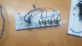
6v on the B+ out. After tracing my work and comparing it to the schematic a few times, I'm 99% sure that my wiring is correct.

I contacted Mr. Millett directly for advice on what I may have done wrong. He responded promptly and told me that he didn't see how the circuit could work as drawn, as the error amp plate (V5 pin 7) should be connected to B+. He suggested I connect the 330k resistor in the schematic at the current limit circuit from pin 7 to B+. This gave me +.4v and some current meter swing when playing with the 100k pot, but nothing more. Unfortunately, he said he may have found the problem after he uploaded the pictures to the web page and corrected it later, however that was 15 years ago and he no longer has the unit.
I'm curious if anyone here has built this supply and run into a similar problem? How did you correct it? I'm learning tube circuit design, but I am in no way experienced enough at the moment to figure out why this supply isn't working without help, so if anyone has any ideas on what could cause my issue (assuming it is a design flaw and not just a wiring error on my part), would anyone be willing to take a look at the schematic in the link above and make any suggestions? I spent months building this and I'm not quite ready to give up on it, but I'll admit I'm getting close.

Thanks for any help everyone,
Daniel

Camper system

I am planning a camper conversion and thinking about the hifi. I have alpine components that can go in the front doors and a rockford sub but I want something with a bit more finesse for the living space.

My thoughts so far to get an even sound all through the back would be a line array with small drivers running from rear doors to the cab along the ceiling. This could also be used to compliment the front door speakers while driving.

Does this seem feasible or any other ideas please?

2-way crossover with 15WU8741T00 advice needed

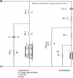
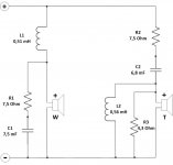
Hi to all. I am very new in DIY, but decided to make Scanspeak Lumine, as heard it at Youtube and was impressed by their clear sound. But as i already have 8-ohm tweeters (the ones from Sony ss-g55, 8 ohm, biocellulose), and decided to use 8-ohm version of SS 15WU8741T00, instead of 4-ohm 15WU4741T00 (mainly to avoid different impedance of tweeter and woofer). It seems that it will be something very different from the Lumine, but I hope that the woofer will give a good quality sound. Followed instructions in "Introduction to designing crossovers without measurement " thread, and made calculations, so I ended with the crossover shown. Can someone explain what is the role of R3 and L2 in the original Lumine crossover, and give advice on this crossover in general? Thanks in advance.

Attachments

  • Lumine-1-Schematic_a.png
    Lumine-1-Schematic_a.png
    13 KB · Views: 623
  • Crossover network new.jpg
    Crossover network new.jpg
    34.2 KB · Views: 548

Help to upgrade crossover

Hello, I have Troels Gravensen loudspeakers, specifically the Jensen ATS model. Jenzen-ATS
Made some changes such as improving or, if you prefer, adjusting to my sound tastes, various caps of the crossover. Seeing the changes that choosing one cap or another can generate, especially those dedicated to high frequencies, I wonder if this is also important in the choice of coils. The cut-off on the ATS is at 2200 hz. Therefore, there is an important area of ​​high frequencies that correspond to the mids speaker. The ATS works with a second order filter and uses a Jantzen model WAX 1.8mH, 0.37omh and 14 AWG coil in the mids section. My question is the following. Could you improve the sound by replacing this coil(respecting the original values)? If the answer is "yes", what makes and models can be suggested?

BR
Toñi

Active Speakers - Dual USB DACs - How To Synchronise USB Output

I've been considering an active speaker project, motivated by the advent of low cost high quality amplifiers (TDA32xx)
I'm coming up against the challenge of low cost computer output to multiple amps

In an ideal world I would use
  1. Source = AMLogic S9xx or Pi or Nuc, running some flavour ofLinux
  2. DSP = CamillaDSP or BruteFIR or similar running on source computer
  3. DAC = USB DACs eg. Topping E30 * n
  4. Amplifier = TPA325n * 2-3
  5. Speaker = 2-3 Way without crossover (handling by computer)

Most of those elements are low cost, "good quality" and sufficiently capable

The Problem
USB is a negotiated link, so there can be significant timing variance between transmissions and between devices. This will probably be an audible problem when "sound" timing needs to be coordinated across multiple devices ie. the DACs when one is feeding left speaker an another DAC feeding right speaker, say​

The Question
Is there a way to guarantee trasmission coordination across multiple USB devices ? Has anyone succeeded in making this kind of setup work ?​

It's possible to purchase additional equipment to achieve this outcome (but these add to the cost and add points of failure) eg.

  • 8 Channel DAC like the Octo or DIYinHK units
    Intermediate processor like the Motu 8A or Auverdion Aurora/Infinitas
    MiniDSP UDIO8

Is there a way to achieve this outcome or am I misunderstanding or looking in the wrong place

Any advice / guidance gratefully accepted

"Grounding" LM 3886 (and other chipamps

I have read through a number of threads about the LM 3886 and the design of the PCB to mount it on. One much discussed point concerning the grounds on the PCB´s concerns the power ground and the large currents going through it and the possible problems of havoc that can be caused by this if done wrong.


Most of these designs have the same or a very similar sequence of connections on the edge opposite of where the LM3886 is mounted and which is , from left to right : negative rail , ground from psu , positive rail , then speaker out + and speaker out - , and then the input and its ground.


So forgive me if there is some error in my reasoning and explain why , but based on my long years as a tecnician and working with discreete amps mostly ,what speaks against forking the input ground trace going to the center of the caps adding the speaker out ground there ? This would change the sequence of connections as follows and would keep the high currents completely away from the rest of the PCB , along with the associated problems ? And all other grounds remain as were....


Sequence then would be from left to right : negative rail , ground from psu , speaker out minus , positive rail , then speaker out + , and then the input and its ground. As is done mostly with high power discreete amps the speaker ground then returns directly to the juntion of the filter- caps . Board size stay the same and could possibly be further optimized. I cannot judge that as I have no experience with it except of what I learned reading in all the threads.

If I am , for whatever reason , wrong please correct me Thanks Michael

elac design flaw lm3886?

Hi.
I been helping out and repairing several elac active speakers.
they have a lm3886 which amplifing the tweeter and tip41 and 42c for the rest,
there is also a tda180 circuit which i dont really understand,
but the problem is that the resistor gets really hot connected on the negative rail to ground.
also had a lot of capactors bad which is replaced.
the negaive vee supplying the lm3886 and tip42 plus tda180 which connect directly to ground with a 2w 500ohms resistor. get burning hot, and it measures 25 volt over it.
I looked at other circuits but cant see any using 500 ohm, on the postive side I measure 9k ohm to grund.
any idea?
best regards after midnight in norway...

Niklas.

Attachments

  • lm3886.jpg
    lm3886.jpg
    272.4 KB · Views: 1,146

Fairchild 670 Drip Time Constraint PCB's

Hey Everyone I need some help

I purchased a Drip Electronics Fairchild 670 board back in 2013 for $400usd. I received the board from Gregory at Drip, but he forgot to include the Time constraint Pcb's in the order. I have been asking him for the missing Pbc's for almost 8 years now, and he always fails to get back to me, or says he'll take a look with no follow up..... I guess i'll just go **** myself then..... (sorry my rant is over) :redhot::redhot:

I'm at the point where I have to get them printed myself from another company to finish this build. Anyways I thought I'd turn to you all. Does anyone have the time constraint pcbs, that can send me a picture. Or possibly a schematic for the time constraints. Anything would help at this point.

Thanks for your help

OTL tubes amplifier based on the ecl84

Who said tubes amplifier had to be warm and lush ? This one certainly isn't 😀 I've got a prototype of this amplifier working on my bench and it has serious slam.

It is based on conventional building blocks: mu-follower for the gainstage, white cathode follower for the output stage. The little triode in the ecl84 has some serious gain, which compelled me to use a relatively heavy feedback to take the gain down. The trioded pentode sections are run pretty hard at 170V and 25ma each. The tubes aren't very expensive but I'll try to run the amp a bit colder in the long term (something like 160V, 23ma). Into a 300ohms load (headphones in mind are AKG K340, senn HD600), it translate into more than needed power.

All the coupling caps are mkp, resistors are a mix of 2W and 0.6W metal film, depending on position (and applied voltages).

attachment.php


The power supply is coming straigth from tubecad's website, with a small twist to use 200V rated caps on a 380V supply. The heaters are biased somewhere around 90V. I use AC and it's silent (no hum) with high impedance headphones.

attachment.php

Attachments

  • Capturer.PNG
    Capturer.PNG
    41.2 KB · Views: 2,274
  • Capturer2.PNG
    Capturer2.PNG
    26 KB · Views: 1,522

Kinergetics Chiro C-500 Amp problem

Been trying to restore this 5-channel amp for a while, BUT the main power PCB has several missing traces (delaminated and gone bye-bye. No schematics seem to be available.

If anyone out there owns one of these amps and is willing to take a few photos of this PCB, I'll be able to have a working amp. Would be happy to pay you for your time & efforts! It is pretty easy to get to and I can give you some simple instructions on opening it up.

Thanks!

Ivan

Jose Duddy New Member

Love Android and Google. Installed new car headset Android 9.1. I am a singer and entertainer and Android is my hobby. 26 wifi philips light bulbs. 5 google minis, 1 google hub max, 1 original google home. 3 google chrome cast 4k, 1 nest doorbell, 1 outdoor nest cam, 1 nest thermostat, 1 Nest X Yale door lock. Needless to say I have built a google eco system...lol.

Thanks to everyone.

Please direct me to a forum to discuss Android Car Headset, and installs and upgrades.

Android car headset 9.1 - Google Photos

Why do these B&W metal domes sound so good?

I'm trying to understand why these B&W tweeters don't have that typical metal dome harshness? They sound alot like planar drivers with very detailed upper top end and never ever get nasty even at very high volume levels. I usually can pick up on the ultrasonic response peak by ear listening to the upper piano notes or cymbals but these things don't sound like they have any breakup mode even though they should. I don't have a good enough measurement mic that has the frequency respose to measure that high where that peak usually resides. Maybe the acoustic lense has something to do with this, suppressing it?

I have the same tweeters in my B&W DM580s. They have better midrange and top end than some $5000 speakers I've heard. I'm baffled by how much dynamic reserve these things have being a 2.5 way design. They are crossed over fairly high around 3.5k 3rd order, so that probably has something to do with it, plus they can play as loud as some larger 3 ways. I did rip out all the old electrolytic caps and installed PP caps which made a massive difference everywhere.

So I just wished I knew the secret to why these tweeters are so good. I have a pair of Thiel tweeters made by Seas that sound similar, but not as open and dynamic. I used to turn my nose up at metal domes, but these B&Ws converted me.

Attachments

  • 20210306_023839.jpg
    20210306_023839.jpg
    1,012.1 KB · Views: 957
  • 20210306_032014.jpg
    20210306_032014.jpg
    352.5 KB · Views: 880

D Class IC amps, are they safe without a heat sink?

Hi,
I'm new to this so please forgive my noob questions


I'm building a ported boombox style speaker from ply with all my components boxed in. I've had a D Class IC amp in the past with a heat sink, it was only 15W per channel but it got really hot! I placed it near the ports so it got good air movement and everything seems fine.


But for this project I'd like to build something 50W per channel with D class IC amp but a lot of the suppliers don't have a heat sink attached and I'm wondering if I need to attach my own? Can I place it near the ports without a heat sink? Or is it just fine to box it in a separate compartment and forget about thermal management all together?

Thoughts?


Thanks 🙂
Projects by fanatics, for fanatics
Get answers and advice for everyone wanting to learn the art of audio.
Join the Community
507,774
Members
7,888,020
Messages

Filter

Forum Statistics

Threads
406,217
Messages
7,888,020
Members
507,774
Latest member
pete2000