Upgrade from FE126NV to FE108EZ in existing build?

I have this kit: Fostex BK-12m Folded Horn Kit - Pair

With the FE126NV installed. I see the FE108EZ is offered as an upgrade.

Are they necessarily 'better' or just different in terms of the sound?

Or, are there other drivers that could be a bolt-in replacement that would be enjoyable (that would work with the existing cabinet).

Just staying with what I have is fine, I am not trying to upgrade for the sake up upgrading, just curious.

Marantz SR7200 buzzing noise

Hi guys.
I try to fix this Marantz SR7200 that gives loud buzz noise in all modes. When switching a direct mode, sometimes noise disappears, sometimes not.
I will be glad for any suggestions.
Also, for some reason, access to "hifiengine" from my region is blocked. There is four service bulletins for this model which can help me, but I can't download it. If someone can help ;//
Marantz SR7200 Audio Video Surround Receiver Manual | HiFi Engine

Thanks in advance.

Cheers!

DI hum problem

Hello all, first time here so please be gentle! 😀
I wasn't sure exactly what board to put this on

Anyway I am running across an issue that is driving me nuts. Live situation. I play a LP through some pedals and then a Radial Pro48 Active DI which splits off to my Vox AC10 and XLR to house PA. I get a nasty hum even with ground lift on the DI. I also picked up a HumX and have my AMP power going into it. Still same hum. I moved the humX to the power of my pedals (MXR ISO brick) but still same hum.

The only time the hum goes away from amp and PA is when I disconnect XLR from my DI. I don't have access to get into the PA other than plug in and set level.

Do you guys have some ideas to get around the hum? I use my amp to help me monitor my sound and need PA to reach the audience.

David

DAC Stereo RCA out to mono Subwoofer XLR in, how to?

Hello there,

Here is my setup,

Optical out from TV to SMSL SU-8 DAC, DAC connected to main amp with a pair of XLR cables.

There is no preamp, I am using the remote from the DAC to set volume, there are no sources other than the TV.

The SMSL SU-8 also has a pair of left/right RCA outs that I would like to feed to my Sanway D1-800D mono full DSP (i.e. can set XO with it, etc.) subwoofer plate amplifier that only has one XLR input.

How can I go from stereo RCA out to mono XLR in?

Ideas?

Tortuga LDR3V2 DIY

Selling my Tortuga pre because my Exogal Comet+’s volume control works just as well and I would prefer one less thing in my signal path.

I bought it from here: https://www.diyaudio.com/forums/swa...diy-ldr-controllers-displays-buffers-etc.html details are also available here.

I can confirm it works and the Apple remote pairs great. It’s not the prettiest, and the lid doesn’t actually stay on but most prebuilt ones sell for over 3x this so if you can put this in a nicer case, you’d still have a bargain. It also comes with the firmware upgrade board.

Selling for $200 plus shipping, will ship anywhere at cost.

I can take more pictures if requested.

Attachments

  • 954CF66A-93E2-4601-807A-D3A2259E5D23.jpeg
    954CF66A-93E2-4601-807A-D3A2259E5D23.jpeg
    585.2 KB · Views: 203

Troubleshoot noise in tube-amp, volume pot dependent

Hi!

I'm finalizing a build of the RH84 SE EL84/12AT7 amp and dealing with some noise issues.

The symptom right now is sort of a buzz that is audible on the left channel only.
This is audible with Sennheiser HD660s headphones which are fairly sensitive at 104dB.

It goes away if the volume pot is at min or max position.
I've read this could be noise coupled to the input wires... I moved a bunch of wire around and it didn't make any difference. The input wires are shielded coaxial.

B+ is regulated with Maida regulator so shouldn't be a source of noise.

I experimented with a regulated DC heater supply and that did eliminate this specific noise, but seemed to introduce a different, barely audible hash.

I ordered parts to try and elevate the heater center tap to about 60V, but is there anything else I can try in the meanwhile?
I have an analog oscilloscope and PC-based spectrum analyzer so can do a few tests and post back if it helps diagnosis.

P.S. The PCB is of my own design, it is the first PCB I've made and so may not be perfect. Although, given that the noise goes away with volume maxed out, I don't think that it specifically is the issue.

Attachments

  • RH84-PCB.PNG
    RH84-PCB.PNG
    125.9 KB · Views: 307
  • 2021-03-30 01.24.17.jpg
    2021-03-30 01.24.17.jpg
    305 KB · Views: 302

Qts & Cms which is high priority or what is a good combination

Hi guys ...specifically for open baffle subwoofer driver, which is more important ???

High QTS ?? Or Low CMS? Or both?
Or a combination of high QTS and low CMS?
Or a combination of low QTS and high CMS?

Or...what is a reasonable combination of QTS and CMS for open baffle subwoofer drivers? (For 15" or 18" drivers)

I know this has been discussed few times, but it always feels like some degree of clarity is missing. So asking again, please bear with me guys...

And secondly BL also comes into picture which may effect the CMS ....

Three way bookshelf speaker crossover advice

A recent two-way speaker build has turned into a 3-way speaker build due to inheriting some free drivers.

I've made up a crossover on VituixCAD and it looks pretty good to my eye, except that the impedance seems to drop to 3ohms at 900hz.
I'll be powering these speakers via an old Onkyo TX-SR705 which is rated to run 4 ohm speakers according to the manual.
Would this be a problem and does it look like I've missed anything? I'm an amateur at this and some people on this forum have a wealth of knowledge!

Tweeter: Dayton Audio ND25FN
Mid: Tang Band W3 593FS
Bass: Dayton Audio ND105-4

Crossover diagram: dayton-pc-speaker-3-way-crossover-diagram — ImgBB
Crossover including graphs: dayton-pc-speaker-3-way-crossover — ImgBB

Thanks in advance!

NAD 3020 clone

Here is the schematic from a 3020B that was simulated using modern transistors. I thought I would experience the equivalent of audio nirvana when I saw the gain/phase plots of this circuit but I was underwhelmed. To be honest, the gain/phase plots look awful compared to a typical Leach amp. Of course looking at a simulation doesn't tell the whole story. But if it looks and simulates less than stellar, why build it? Some of the blame could be the modern transistors used to make it. I am surprised by the number of small caps sprinkled around the circuit to shape the frequency response. Sure, it's flat +/- 3db 20 to 20K but the phase response is iffy and it appears that there will be stability issues at high frequencies. Blame the modern transistors, I guess. Has this amp been cloned? Does the NAD 3020 deserve it's cult-like reputation??

I guess the search for the audio holy grail continues......

Attachments

Designs using certain drivers... How to search

I'm really bad at knowing all the advanced ways to correctly search on the internet. I have spent two days trying to find designs what utilize a couple of speakers I own. I have the 12 inch Kappalite LF woofers in a 3 cu ft enclosure, with endless loading options. Ported sealed all works. Even different size ports are possible.
I also own a pair of B&C 6md38 midrange. The plan is to make a 3 way pair of very high efficiency speakers. To keep it high efficiency, I figured I'd go active with DSP. I'm just trying to make sure there are not any designs already made using these drivers before I start. I also need to find a good hi frequency transducer of some sort. Whether it be normal tweeter, AMT, ribbon, Etc for a high efficiency design. Any suggestions on how to search for this would be very helpful. I don't mind doing the research I just don't know how very well. Thank you

Field 1: a floating circuit is...

A circuit that has no connection to earth/ground/chassis ground, is that correct?

(Of course mains earth has to be connected to the chassis)

I‘m asking because during my builds, I‘m often too impatient and can‘t resist to hook that beast and have an ear full.
The wayne‘s BA18 linestage for example was deadsilend in ... floating? ... state. It is grounded now and still dead silent, haha! [emoji2]

CDP-337ESD (KSS-190A) not working

I am new to this forum, and would be grateful for help. Over the years the drawer of my Sony CDP-337ESD became sluggish. Eventually, it would not come all the way out by itself. So I changed the two belts in the KSS-190a transport to new ones. This improved things, but the speed of the drawer going in and out was still not as fast as it was when new. So this time I cleaned all the sticky old grease out from all the gears and put new grease on. Unfortunately, after I put everything back together again, now the drawer does not move at all. The front display says "Open" and "Close". There is no sign of any activity from either of the motors and the CD does not spin. The two Mabuchi RF-510T motors that drive the belts and gears are still OK. Any ideas where I might have damaged the 337ESD?

Refoam or replace???

I recently purchased a pair of Duntech Crown prince speakers that have been in storage for many years. the foam on the woofers is just at that point where the foam is rotten. they haven't fallen apart yet but you can tell one good bass note and they are toast!

SO, I have 2 options.

1- refoam. Now I can have Bill Watkins do the refoam work. he has some sort of special method to align the voice coils in the gap electrically without having to cut the dustcaps off. Dynaudio woofers don't have dustcaps anyway. I did some research and found a place that supposedly has the correct foam surround kits imported from germany. I believe this to be a good way to repair the 24W75 woofers as they are no longer available from Dynaudio.

However.

2- I did contact Duntech and Dynaudio will sell them custom replacement woofers with rubber surrounds instead of the foam. this is a more expensive option but in the long run they will never rot out again.


So those are my two options. There are advantages to both. 1- the stock woofers are matched and voiced to those cabinets. granted changing the foam surround may alter the drivers characteristics slightly? and the spiders could be weak anyway.

Going with new woofers has the advantage of rubber surrounds and possibly be a more advanced driver with better specs i don't know. But will they be as matched to the cabs and each other as the stock woofers?


Thoughts?


Zc

Redesigning the Calpamos with digital crossovers and a new woofer

I have vehemently decided that my next speaker upgrade will be hands down a high end PA speaker, definitely want horns for the mids and a 15 inch for that thumping bass. I have been looking at the Visaton Monitor 890 Mk3 and the Calpamos. And although I can get the Visatons for cost price and prefer it in every way, it still ends up more expensive than the Calpamos if I were to buy the Calpamos without the kit and purchase the drivers separately and digital design crossovers. The difference being about $400 US which is essentially around $600 Aussie dollars.

Putting the soap story aside, lets go with the premise that I go with the Calpamos as the base(if there is any objections and a preference to the Visatons speak now) I am keen to change the 15inch driver to one that plays a little better towards the top end as low extension is not important for me. I have 2 Dayton RSS3150HO which play superbly at a QTC of about .44 start and stop on the dime.

I have chosen the B&C 15NDL76 or the B&C 15FW76 to switch with the original Faital Pro 15PR400 if you have better options please feel free to recommend especially if you know about the Calpamos, the horn mid is the Faital Pro HF201 in a P Audio Ph2380 throat horn flare which can easily go down to 650hz in the original design.

Now, I know that each cabinet has its own unique crossover but I am sure DSP will manage everything in its crossover design and corrections to an extent. I am trying to keep as much as possible the existing design and just find the most appropriate enclosure size for the new woofer.

I know enough about speaker design to ensure I haven't missed anything, in particular making sure that both drivers will reach the end of there frequency spectrum.

Is there anything else I need to watch out for before I embark on this possible project?

If the sub woofers are not as sensitive would that be a problem?

Creating a Stencil Template for a Synth, Mixer, Etc ...

Happy Saturday DIYAUDIO FAM ...

I pray everyone that is reading this post and your families are safe and healthy.

Now that I am off work for a while and confined to the house I started repairing a lot of old stuff I had in the garage.

I was wondering if someone could assist me with a project? Hopefully, I am posting it in the correct forum ...

I have the Cameo 4 cutter that I use to make stencils, stickers, shirts, etc. And I was wondering how I could use CAD or a similar program to make a template of my X-Station Keyboard and some Channel Strips. I could create the template and then have the Cameo cut out the template.

I want to repaint the keyboard and then repaint the markings using a stencil-template. Has anyone ever done this before? I have a tendency to overthink things so any suggestions, guidance is appreciated.

2 stage Passive LCR RIAA

Now that I have finished my SP10 turntable project, I want to build a high end phono stage to meet and exceed it. There is a well reviewed phono stage that has the following published details.

No caps or resistors in the signal path
Point to point
Pair C3g tubes in input stage, 2123 Hz, passive regulated DC heaters
Pair C3g tubes in the output stage, 50-500 Hz, AC heaters
LCR network transformer driven
39 db output level for MM
Step-up transformer for MC
Power supply 6CA4/EZ81 tube rectifier w/choke filter
Input impedance 47Kohm/200 pf
Output impedance 1200 Ohm
Gain 39 db

I found these transformers that have similar construction to the commercial unit. Noguchi Tranformers FMQL and FMQH RIAA equalizer coils.

Are there any known schematics that can be modified or anyone up to the task to sketch out? Or too difficult a task?

FAST/WAW speaker with ScanSpeak 22W/8857T-00 and HiVi B3S or RS100 or something else?

Been following this thread:
10F/8424 & RS225-8 FAST / WAW Ref Monitor

I agree with a lot of the theory surrounding this speaker and setup, that's kind of rare for me. Mainly that a speaker should be centered around the largest woofer.

Is there a SS 22w thread?

I like this enclosure for the 22w:
http://www.troelsgravesen.dk/Ellam-3W/ellam-flex-3w-cabinet-large.png

I might have to change the height, but I figure if I keep the length the same it should be okay. Or I might build a ported enclose that is tuned low. But I think I would like a TL.

Which full-range should I use? I like the look of the Seas 3-4 inch or at least a cast basket.

Some things took me way to long to realize:

I don't like highs, especially dome tweeters.

Most speakers have too much midrange and way too much treble, for my taste.

I usually EQ the treble down by 8 db and mids down by 6 db and raise the bass up by 12 db on a 2-way.

I have a "flat FR response" Dayton C-note kit I listen to now and I even have to turn the treble way down and bass way up on the receiver.

Audiophiles "trash" Bose speakers (and I do to 😀), but who is listening to these C-notes? They are PAINFUL 😱 to listen to un-EQed.
I had some Usher 2-ways in the same location.
Bought them from Joe D., the usher consultant. Put every usher woofer and tweeter in them, similar issues to the C-note.
I like Bose 301's better than any domed tweeter speakers I had in that location.

I do okay with ribbons and AMT's and Vifa/SS ring radiator, but I think I can do without.
Maybe a FAST with ring radiator or AMT?
Also I don't know what the acronym FAST stands for :rofl:

Freiheit’s Versatile Amplifier Monoblock chassis v 01

Dear friends,


I am currently building an amplifier chassis for use with M2X and aleph J.


I was wondering if someone could please have a look at the attached design and give me feedback before I order materials. I am not very experienced and not trained.


The design is open source and can be used by anyone. For a quick overview, consult the attached pdf - see below.


If someone would like to replicate the design, the full cad file is available here. However, it is not a stable design as of yet. Also, it requires the builder having access to a 25x30cm heatsink.


My questions are:


1. Anything strange? What would you do different?


2. Are the following items too close to the 500 VA transformer?

  • the speaker protection board
  • the speaker protection board transformer
  • the softstart
3. Do you agree with the distance between M2X pcb and power supply (I have left a lot of "unused airspace" between them).


Thank you!


Please note that I may not reply immediate to this threat as I am currently not well.

Attachments

FS JLester TPA3255 48v passive post filter feedback amps and power supplies £99 each

Up for sale, a total of five pairs of unfinished TPA3255 amp boards and power supplies. All brand new.

Each pair includes

  • One TICORE260BTL TPA3255 STEREO PFFB 48V (PARTIAL KIT) AMPLIFIER MODULE with the four premium coilcraft VER2923-103KL inductors installed.
  • One AliExpress 800w 48v low noise power supply (KAYPW Switching Power Supply Light Transformer, as used by XRK on his builds)

attachment.php


attachment.php


Asking £99 per pair (power supply and amp) plus shipping. Discounts if you want to buy more than one.

To complete each amp board all you needs is:

  • One ATS-TI1OP-519-C1-R3 heatsink (available on mouser, costs just over £5)
  • 2 pcs OPA1656 or LME49860 on SOIC-8 to DIP-8 adapter ENIG PCB - readily available on the internet
  • 4pc tank caps: 1800uF 63V low impedance (e.g. panasonic EEU-FC1J182, about £2 each)

Plus other ancillaries and chassis etc... which are not included.

You will need to make the following easy amend to the boards as TICore260BTL Version "V1A" has a small fault that when right channel exceeds certain power output, the module goes into protection mode. This is overcome by lifting C17, then connect the ground of C17 to ground plane on C16. (Picture attached)

Good performance from these. Any questions please ask.

Gavin
Oxford, UK

Attachments

Headphones 3Dprinters and exotic enclosures

I am wondering with 3Dprinting is it possible to make scaled down versions of more uncommon speakers enclosures for headphone applications, such as transmission line. My audio and physics knowledge is very limited, so I am wondering if you guys would help me understand what’s possible. Id like to build some headphones that wouldnt not have been feasible without 3DP.

The most Ive kind of understood is wave lengths and back loaded horns. The reason I learned (sort of) was because I was searching for impressions on madisound’s tiny back loaded horn computer speakers they used to sell a few years ago (cant find on their website now but it came fully assembled and was ~$100pair) and if they actually worked or were just show. It appeared that they werent large/long enough to be effective.

I am a newb that ocassionally browses diyaudio and diyma. I built a pair of open baffle Manzanita Ultras and put together a car audio system where I learned about crossovers and REW. I am mostly into headphones though and actively participate and share impressions & measurements on other forums. Thats a summary of my limited experience and sincere interest.

Please advise what’s possible and if there are computer programs able to simulate results with these tiny dimensions and headphone drivers. Even a program for typical open/closed back phones would be helpful.

Thanks, -Phil

Edit: I am willing to put in the time to understand the basics - just wondering if you could shortcut me to whether its even worth looking into since it may be impossible etc. ... Help me get pointed in the right direction.

Edit2: Also didnt know where to make this thread. Full-sized headphones generally use a single driver. And the miscellaneous subforums look much less trafficked. 🙂

What is going on with my OEM head unit output

I am trying to connect an after-market DSP to my OEM head unit. The issue is that the signal is not always being output by the head unit. When the system is first turned on with everything connected, the signal is off, but when the RCA is unplugged from the DSP, the signal immediately turns on and stays on after being plugged back in. Actually, just disconnecting the negative side of the signal from the DSP causes it to turn on. I know that the signal from the head unit is not turning vs an issue with the DSP because I have a scope connected to the head unit's output and can see when it switches on.

My first thought was that it is either some load sensing circuit to ensure the expected load is connected, or some kind of protection circuit when it senses too much current being drawn. I measured the OEM amplifier input impedance and it measures at either 500 ohms or 50 ohms, depending on the resistance used to measure it (another mystery perhaps). I tried putting dummy loads of 50 and 500 ohms between the head unit and DSP, but it still only turns on when you disconnect from the DSP. I also tried loads of 47, 250, 1k, 5k and 10k for good measure, and still no luck until I unplug from the DSP and plug back in. What could be going on here?

A Simple TPA3250 BTL Board

I recently assembled a 3e-audio tpa3251 amplifier. I was really happy with the result, and thought it would be nice to have a similar amp board built around the tpa3250. I don't need a lot of power (20-30 watts is more than enough), and the tpa3250's power pad down design allows the PCB to be used as a heatsink, allowing for a smaller board. 3e-audio appears to have made a tpa3250 board at one point, but it is no longer available.

I haven't made time for diyAudio projects in the last year or so, and combined with the desire to have a tpa3250 board, I thought I'd take a stab at designing my own. The first PCB I ever designed was for the tpa3118 chip; I called it the Hot Doug, as an homage to DUG's tpa3116/8 board. (I built an amp around DUG's boards over five years ago, and it's been in continuous operation in our living room ever since.)

Also noteworthy is the Gmarsh-designed Wiener Pro prototype based on the tpa3250. He doesn't appear to be active on diyAudio any more, unfortunately.

So here I present the "Hotter Doug" tpa3250 board. This is by far the most complex board I've designed; in the interest of trying to minimize problems, it is essentially a slightly simplified version of the TI TPA3250D2EVM (TI's own evaluation module/reference design). Design notes:
  • Fairly compact: 92x73 (mm).
  • Component references exactly same as TI EVM.
  • I originally wanted to use the "deliciously overkill" VER2923 inductors, but decided instead to use the Coilcraft ua801x series for cost and space savings.
  • Uses only 805 or bigger SMD components. This is my personal threshold for what is comfortable to solder by hand. (Also allows for more caps to be C0G.)
  • Strictly BTL (stereo), does away with all EVM jumpers except SE/DIFF input.
  • Omits the EVM's supervisor IC (for managing the RESET pin) in favor of continuous 3.3v on that pin (copied the idea from the tpa3220evm-micro).
  • Nearly continuous bottom layer groundplane, stitched to top layer groundplane, to make whole PCB act as a heatsink for the tpa chip.

My main goal with this version is just to have something that works. Unless I made a copy error, the schematic should be valid, since it's a direct clone of the TI EVM. Component density is high (for me anyway), so my biggest concern is soldering errors. I plan to use my frying pan/skillet method. Assuming everything works, some ideas for future revisions:
  • Take measurements, investigate post-filter feedback.
  • See if there's a simpler/smaller/cheaper way to derive the 12v and 3.3v power rails. The EVM uses a lot of board space to do this (LM5010 SMPS for PVCC to 15v, LM2940 LDO for 15v to 12v, TLV1117 LDO for 12v to 3.3v).
  • Look for a simpler/smaller/cheaper way to do the input buffer (that allows single-ended or differential input, and supplies the necessary differential input to the TPA chip).

But that's getting ahead of myself! At this point, I think I'm good on the layout, other than minor tweaks---unless somebody points out potential issues that I'm not aware of! I'm slowly working on a BOM and Mouser project. After getting some feedback, and finishing the BOM, I'll post the Kicad files as well as the bill-of-materials.

Thanks for looking and any feedback!

Attachments

  • tpa3250_btl_amp_v1.pdf
    tpa3250_btl_amp_v1.pdf
    111.1 KB · Views: 266
  • pcb_top_solid.jpg
    pcb_top_solid.jpg
    276 KB · Views: 578
  • pcb_bottom_solid.jpg
    pcb_bottom_solid.jpg
    405.8 KB · Views: 576
  • pcb_top_3d_render.jpg
    pcb_top_3d_render.jpg
    370.3 KB · Views: 600
  • pcb_top_3d_raytrace.jpg
    pcb_top_3d_raytrace.jpg
    356 KB · Views: 570
  • pcb_bottom_3d_render.jpg
    pcb_bottom_3d_render.jpg
    134 KB · Views: 609
  • pcb_bottom_3d_raytrace.jpg
    pcb_bottom_3d_raytrace.jpg
    162.6 KB · Views: 197

MiniDSP question

I am curious as I have never used miniDSP.
My surround speakers in my Dolby Atmos theater are Dunlavy SM-1’s
I have built subwoofer enclosure’s with single downfiring Scanspeak 25w/8565-00 that’s the SM-1’s sit on top of.
I am using passive crossover on the Scanspeak woofers.
If I were to use miniDSP for ONLY the woofers would I have delay issues with my home theater setup?
I guess I should run my SM-1’s thru miniDSP as well so could help delay between the monitors and woofer , but would I have another delay problem being that that pair of speakers were the only ones that are fed via miniDSP.
Digital is all new to me.
Thank you in advance...

Let's talk about XO above 10K hz & 1/4 WL law

Hi,

In conventional 3 ways or more loudspeakers, best soundstages often result from a treble to medium being near a 1/2 wave length center to center spacing. Because the 1/4 wave length rule is impossible at those frequencies.

Now, Most of music is under 10K hz, there will be always few exceptions and instruments that climb high as piano or some instruments having very high harmonics that we still can perceive in the flow, but again all the story is often below 10 k Hz.

We often wan to cut-off outside the said area of ears sensibility as exposd in the Fletcher&Mundson curve. It translates by several approachs like hrned tweeter crossed below 1500 Hz, Full range from 4" to 2" sizes, conventional dome tweeters of 1.25" size, some ribbons and AMT of big size that handle for the hugest XO below 1k/1k5 Hz and of course all the horned compression drivers with possible low XO in home situation if the wife supports horn and have not fulled your suitcases yet because of that !

Now what happen with some design with very high cut-offs and more or less stiff slopes ? Say above 10K hz . For illustration like some design of ZU loudspeakers , some english style design like old Spendor or newer Harbeth with two differently sized tweeters and so on ???

I'm asking myself if I could not XO my ScanSpeak 2.5" 10F FR driver around 10 K hz or more with a first and second order slope 😕 Why not with some excelent tiny 3/4" Peereless, Monacor and numerous not so bad if excelent cars tweeters (Audax made some crazy good sounding ones with Fs around 6 k Hz for instance).

For the FR - full range- enthusiasts, a <300 hz to > 10 K hz standalone driver has certainly some appeal ! A logic behind it could be a size that makes the driver good enough for the task : not slam to perform below 300 hz (XO dependent of course) and not laser beaming treble as well (same XO dependent of course)

Trade offs discussion of course !🙂

IRS2092 questions with reference design IRAUDAMP7D

I have a question when I am Looking at Amplifier Schematic, Channel 1&2 and the FET2 that cause of RED LED lighting.
The FET2 control by SD through a diode and resistor connected to a gate pin of the FET.
I understand the SD signal coming from the protection circuits is a value of a negative voltage.
My question is how does this voltage cause the FET to switch so that the RED LED
(Prot) turn on?
Is there a connection to the fact that the same SD signal is also connected through the diode and the resistor to the CD pin of IRS2092?

Thank you
Doron

Choke-Loaded Cathode Followers - A Question

I would like to try a choke-loaded follower (6AS7G) to drive the grid of my zero-bias, 211, Class A2 amplifier.

The behavior of chokes in a plate circuit is widely discussed...due to inductive collapse, a choke is capable of voltage swings nearly 2x that of a resistor in the same position. But what if we use a very large (50 H) choke in a low-impedance environment such as the load for a cathode follower?

A resistive-loaded cathode follower generally has a gain of ~0.9 or so under normal conditions. What if a choke is present as the load instead of a resistor? Will the inductive collapse of the choke effectively raise the gain of the follower to ~1.8 instead of the usual ~0.9 - or does the inductive collapse not enter the picture in this situation?

Oh and BTW, the bottom of the choke will be returned not to ground, but to a negative supply so the follower can swing equally + and - about the zero-bias point. The DC bias current flowing through the choke is selected so that the follower output is at zero volts in the resting, no-signal state.

Thanks for any insights!

FAST or STAFT (WAW or STAW) Which is Better?

I recently made a 2-way bookshelf as an homage to the venerable LS3/5A. However, I implemented a crossover well above the usual 2.5kHz to 3.5kHz frequency normally used for 2 way speakers. I put the crossover at about 5.5kHz and used a modified inverted passive Harsch XO to achieve semi-transient perfect behavior and the resulting sound is so natural and great sounding. As the so-called “telephone” band that is so important is often described as frequencies from about 500Hz to 5kHz where most vocals, instruments, and soundstage spatial cues are contained in this frequency range. It would seem that the speaker I made might be called a Super Tweeter Assisted Fullrange Texhnology (STAFT) - the long lost brother of the FAST speaker. Some people like the WAW acronym vs FAST and mods have been going through all the threads and renaming them or adding WAW wherever they see FAST. So in that case, the acronym would be STAW or Super Tweeter Assisted Wideband (STAW). Whatever you like to call it, what I am noticing is that it produces a very natural lifelike sound with superb imaging and soundstage. So much so, I am building very special wooden cabinets for what was a foam core prototype.

Here is the measured frequency response showing the contributions from the woofer and the tweeter:
870609d1598355186-rst28f-dc130a-foamcore-homage-ls3-5a-ls3-5a-foamcore-dc120a-rst28f-freq-meas-fdw7-jpg


Here is the measured step response exhibiting a near right triangle shape indicative is a transient perfect speaker:
870181d1598224698-rst28f-dc130a-foamcore-homage-ls3-5a-ls3-5a-homage-dc130a-rst28f-meas-step-resp-jpg


In this case, the woofer is really a wide bandwidth woofer capable of producing bass and mid range up to 5kHz and the tweeter is a conventional soft dome capable of crossing as low as 1.5kHz but I chose to do it at 5.5kHz. So the STAFT has the advantage of very nice highs and shimmer that many of us miss from a single cone fullrange driver. Even the some of the best and most highly regarded fullrange drivers like the Scanspeak 10F really only go up to about 16kHz. Whereas a true dome tweeter goes well above 20kHz. And the bass from a “midbass woofer”‘ is generally a lot better than the bass from a fullrange driver. So I suspect that this combo may just be the best of both worlds.

One other thing to note is that most natural sound sources like voice and instruments tend to lie either below or above the 5kHz to 7kHz range. Thus, the crossover doesn’t have to split the critical human voice or piano right in its most important (and audible) 1kHz to 3kHz region.

Here is the simple crossover:
870177d1598224698-rst28f-dc130a-foamcore-homage-ls3-5a-ls3-5a-homage-dc130a-rst28f-xo-schematic-v02-jpg


And this is the speaker implemented in foamcore:
870175d1598224698-rst28f-dc130a-foamcore-homage-ls3-5a-ls3-5a-foamcore-dc120a-rst28f-build-photo-jpg


And a wooden version that will look something like this is being built:
877196d1600586968-rst28f-dc130a-foamcore-homage-ls3-5a-ls3-5a-homage-assembly-v01-render-jpg


I have been listening to this as a nearfield monitor for several weeks now and really enjoying the sound. I love the precision soundstage and imaging. I like how natural it sounds. I like the dynamics and the presence of high hats and cymbals. The upper end response of the RST28F-4 tweeter is remarkably clean for a $37 tweeter. I think what also contributes to how clean the tweeter sounds is the very high crossover so that the cone doesn’t move much and this doesn’t distort. The midbass is a low cost DC130A-8 treated paper cone. It was chosen for its deeper bass reach in a small sealed cabinet vs the more expensive RS150 or RS150P variants from Dayton.

This speaker also has a very benign electrical impedance curve:
870182d1598224698-rst28f-dc130a-foamcore-homage-ls3-5a-ls3-5a-homage-dc130a-rst28f-xo-meas-imped-v02-jpg


Definitely never drops below 7ohms and averages closer to nominal 10 to 12ohms and so is perfect for most amplifiers to easily drive.

So the question is, would a STAFT generally play most music better than a FAST? Maybe it depends on if you really like the sizzle of a true tweeter.

We have of course see large 8in or bigger fullrange drivers with a super tweeter assist
But what I am calling for here is to pick a good wide band midbass or woofer rather than a fullrange driver. Perhaps the RS225-8 and an RST28F-4 in a waveguide with a high XO would be a similar type of thing? A modification of this system
Might produce another STAFT type speaker:
Passive XO for Time-Aligned RS225-8 and RS28F in Waveguide

Mucking about with damping and stuff.

Hi All,

I thought i'd document my current project, a hybrid centre speaker for my home theatre system. I'm currently building the above to compliment better my current left & right fronts, which are a no-baffle fullrange complimented with a TL sub and a horn loaded ribbon tweeter. The current centre is an old wharfdale devondale 3 lying on it's side. The wharfdale is great, but i think i can do better.

I'd decided on an open baffle mid (pioneer DSS9 midrange i'd had sitting about for years) and horn loaded ribbon (another pioneer unit), vertical layout, with a 12" bass on each side. I'm not yet convinced about sealed/open benefits of the bass drivers, though with a Qt of about 0.5, i could go either way, i'll cross that bridge later. Anyway, onto the mid and tweeter. Flush mounted onto a piece of hardwood, 1:1.61 offset, fired up REW and pulled out a linkwitz style mic and measured the midrange.

pioneer_centre_first_measure_midrange.jpg

Oh dear. Listening, there was a distinctly gritty sound. Something was rattling around in the magnet gap. Undeterred, i unscrewed the 3 magnet fixing screws with polygrips, the old glue presented no issue and pop, off came the huge magnet.

magnet_gap.jpg

Yep, crap in the gap. After a blow out with the compressor a good scrape with a bit of blunt stainless (from a windscreen wiper) then a final tweezering out, the gap was empty. The voice coil appeared to be edge wound, silver coloured (plated?) and wound on paper. The cone, vapour deposited coated titanium. Quite a bit of effort gone into this driver, worth saving.

voice_coil.jpg

Back together, re-aligned and re-measured and voila!

pioneer_centre_midrange_magnet_cleaned.jpg

Now to deal with those nasty breakup modes...

3rd Order Crossover Reverse Null

I read that even order crossover that has good phasing will have a deep null when the polarity is reversed. Will this apply to odd order crossover? I have tried to sim a crossover for my project and when I reverse the polarity, instead of having a deep null, it rises up.

Also, in XSim, what is the difference between as derived and as measured? Which one should I use if I got the drivers data from tracing the manufacturer specs?

I attached the files that I use for my project. The .dxo is also in that file, maybe if someone want to help me to design a crossover? Thanks!

Attachments

  • Crossover Project.zip
    Crossover Project.zip
    876.3 KB · Views: 55
  • As Measured 1.png
    As Measured 1.png
    289.4 KB · Views: 368
  • As Measured 2.png
    As Measured 2.png
    291 KB · Views: 352
  • As Derived.png
    As Derived.png
    299.2 KB · Views: 352

Anyone heard a Grundig Fine Arts M-100 CD Player?

Hi,
I have the chance to buy one of these players quite cheaply. I have a strong recollection form somewhere that the 'Fine Arts' range was very highly regarded but I can't find find any specifics.

The one I'm referring to is the MT-100 and is a kind of gold/champagne colour. It looks about 3/4 width as if it came from a mini stack system.

Anybody heard one of these? Is the fine arts range similar to the Sony 'ES' range. i.e. is it a special flagship range?

Any help would be much appreciated.

Regards,
Martin 🙂

Edit: Just worked out it is actually an M-100 😀

Oops! My research may be more effective now.

Back to Google ..............................:smash:

Attachments

  • grundig_m_100_cf__450576.jpg
    grundig_m_100_cf__450576.jpg
    3.9 KB · Views: 354

Meridian 557 vs. Rotel RB-1090

I'm looking for a different amp to power my second set of speakers in another room. I currently use a Meridian 557 in my office which is my main listening room (yes, because I work too many hours) but it's not a place for listening with others. I've been using a Rotel RB-990BX to power the speakers in my family room which has space for lots of people but the 990 only has single ended inputs and doesn't match up to the Meridian 557 in sound quality. I'm thinking of getting either another Meridian 557 or perhaps a Rotel RB-1090.

Let me know if you have experience listening to both the Meridian 557 and the Rotel RB-1090 and how you feel the sound quality compares between these two amps.

Thanks!

Marantz SM6100sa digi-resto-mod phase I

Hey everyone. I haven't posted here in years. I know just enough to be dangerous. I just completed the first phase of restoring my Marantz 2CH (circa 2000-ish). This was one of my favourite amps because of it's simplicity, but lately I noticed the sound falling flat. It was never a Bryston but it was getting outright boring.

20210414_190141_s.jpg


I upgraded components based on the Ver.2 upgrade parts manifest (attached) as well as some things that stood out to me:

- Replaced all electrolytics with Nichicon audio
- Instead of the Ver.2 spec 15000uF main caps, I used 10000uF caps like before, but placed a pair of 47uF Nichicon Muse caps closer to the transistors
- Replaced the secondary rectifier bridges with schottky 1A diodes
- Replaced the film caps with WIMA polypropylene 2.5%
- Replaced the main power traces with symmetrical 18GA copper
- Replaced the input/output wires with shielded copper
- Shielded the AC
- Removed the variable input

20210417_223857_s.jpg


I can say now that I am a believer in basic stuff that some have called snake oil remedies. The difference is night and day! This amp sounds better than anything else I've heard out of Japan. Premium audio caps, schottky rectifiers, wire shielding, and trace fortifying make a huge difference when combined.

Phase II will be installing my USB 24/196 DAC directly into the case, eliminating the interconnects and yet more solder joints.

Out of this project many questions arose that I wonder if you could help me with. Don't bother writing a novel when a sentence will do:

1) If I put my ear against the left speaker with no inputs, I do hear a VERY faint 60hz hum. The right speaker is dead silent. When I play music it sounds crystal clear. Any ideas where to start looking? The Sanken transistors are original and have never been abused. The JRC2068DD op-amps are original as well. Those are the things that are great about this amp so I didn't touch them. Here is a top-down view and I've attached the PM8200 service man pages which have the same output stage.

20210417_223845_s.jpg


2) I haven't tied the shielding down yet because the amp is ungrounded. Should I a) Tie them to the floating case? b) Install a grounded power cable just for the case/shielding or c) tie them to 0V?

3) Why do they put the rectifiers on the audio board? I understand that the caps need to be close to the transistors, but why not rectify the power and smooth it with one set of caps then send it over to the audio board and smooth the ripple with a second set of caps, thereby removing the AC current from the audio side? Two smaller caps are the same price or less than one cap of the same size anyway. I would have removed the bridges from the board already if the hum was coming from both speakers.

Thanks in advance and also thanks for all your inspiration!

Attachments

DIY custom speaker 3 way central channel.

Hello guys. I am totally new with diy sound but i want to try to make my first custom speaker.
I know i am trying something very difficult for 1st project but i want to give it a shot.
I want to make a central channel for home theater.
I want it to be MTM style and particularly
woofer-midwoofer-tweeter-midwoofer-woofer. It will be a 3-way system.
I will use one tweeter: Monacor DT-28N 1-1/8" Dome Tweeter With Waveguide
two midwoofers: Dayton Audio RS125T-8 5" Reference Woofer Truncated Frame
2 woofers: Dayton Audio DC160-8 6-1/2" Classic Woofer (i would prefer to go with the reference but i cant find it in stock)
The crossover points i will use are 375Hz-3000Hz (or maybe i will change it to 3500Hz to be more safe for the fs).
I have designed a crossover in xsim but there is a range where the impendance drops a little below 4 ohms and i am afraid for my amplifier.
Is it going to be a problem? I haven denon 2700h.
I attach some photos of the system in xsim (2 possibilities).
Do you have any advice?
For the drivers or the crossover? Should i change something?
I want to have something to start with and then i will improve it.
Thank you!

Attachments

  • 1.png
    1.png
    147.3 KB · Views: 157

Polypropylene "safety" cap for audio ?

Looking at mouser, I saw and bough Vishay 275V 0.1uF polypropylene safety cap's, an exact replacement for the coupling caps in my Yaquin... Never saw anyone ever mention this type for audio...


I know folks say PIO, Yellow drops and so on, generally stay away from electrolytic's (with exceptions to every rule) just never heard anyone use or like a safety cap....

Need some advice for my car audio project

Hello,
I own an honda civic VIII from 2007 (EU model), and i have the project to increase the sound system for years. I know basically nothing about car radio, and i don't care of what's on the radio, i want a good quality audio system for good music 🙂

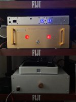
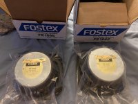
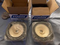
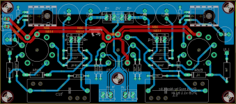
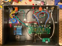
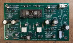
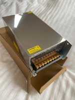
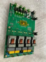
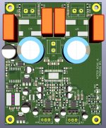
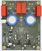
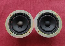
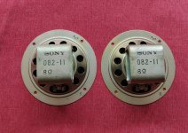
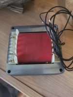
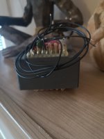
I bought some good speakers and amp (xrk971's TPA3255) some times ago, but never took the time to finish the project. Basically i have the speakers / psu / amp, and i was thinking of a dac - player.

Thing is, i am also working on a project i called "Mini-Soekris". It's a portable music player that i feed with a 5v psu, with this stuff :
Soeris dam1141, nanopi neo3, silent switcher psu, amb α24 as buffer / SE to Bal converter, and a opa1656 headphone amp. All that in a tiny Takashi MXB4-7-11 (yes it will fit, but there won't me much space left believe me :yes: )
The music and linux system will be on sd card, i will use a very simple linux with basically only mpd. I will configure a dummy alsa mixer to communicate with the soekris, so i should use the dam hardware mixer. There is a very practical api for soekris somewhere in the internet.
The goal is to connect to the NEO3 in wifi and pilot all that with a mpd client, and eventually some termux command to change a few parameters of the dac if i need, like the filters.

As i am building this mini-soekris, it looks like the perfect player for my car system. It will have a balanced and buffered output (with mini-xlr), so i will directly connect it to the TPA3255 amp. Also there is a small storage just under the car radio where it would fit nicely, and i have direct access to the amp.

The only missing thing is that it is a little dangerous to use my cell phone to command all that when i am driving. It would be practical if i could use the steering wheel of my honda for basic command (pause, vol +- and track +-).
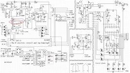
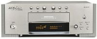
Thing is, with my honda, there is a lcd screen on the dashboard, for climate control and date etc. The car radio command all this, so if you remove the original car radio you loose the climate control and time. You need to use a small box, in my case the Connects2 CTSHO002, to interface to some aftermarket car radio. I saw on the the CTSHO002 schematic that there is two output cable, speed pulse and amp remote.

This amp remote is surely the steering wheel. Thing is, i don't know anything about how it is working. I really hoped somewhere here would have some information, if there is some standard involve. If it's digital, and it's surely is, i guess my only chance is some kind of micro-controller to interface it with the gpio of my NEO3.

The other solution would be to add these basic command directly to the mini-soekris front panel. I am not sure at all if there is the space for it, even if i use some very low profile encoder or buttons.

Regards

Sockets and Plugs for Umbilicals

I've seen a few builds lately where people have used umbilicals to connect the power supply to the business end. The existing threads on this mostly seem to complain about the high cost of the parts. I found some Switchcraft stuff on Mouser, but it was more than $25 per piece! But I think I have now found a good source for these, namely, ElecBee.

Their GX series of 'aviation connectors' look like just the thing. E.g., the GX 16 comes with 2-10 pins, is rated for 250V and 4-8 amps, and a set---cable mount plug and chassis mount socket---is about $3 for any number of pins.

There are beefier models, like the GX30, which is rated to 400V and 20A (for the 4 pin model) and is still less than $15 for two sets (i.e., enough for a complete connection).

There are several other series, as well, which get a bit more pricey (but still not too bad) and have even higher ratings. E.g., the P-series P32 4-pin is 50V/40A and about $18 a male-female pair.

They sell connector cables, too.

Sorry to sound like an advert, but I've been looking for these for a while!

Hifonics VIII Zeus in protect

This amp will COLD power up if you let it sit for an hour un-touched, but as soon as you try to test anything or plug anything in like speakers, RCA, or practically touch anything with the oscope, etc - it drops straight into protect like it's scared.

Its funny when it tries to power up, I hear it some stressing through the transformer but twisting it changes nothing. To me it seems like the amp tries to HOT power up about 3 times and then stops as thats what I see it pulling on my bench PS. Currently how it sits it is stuck in protect unless I wait. I tried draining some of the caps but I must not be draining the right one; because then I can probably get it to power up correctly for a few minutes or so. Its using TL594 and a new one for me for latch - which is a 14-pin device with 2B4 HA17324 on it. Looks a little slick too not like a normal IC. Looks custom maybe? Manufactured marking looks like a little camera inside of a circle. Thought it was OnSemi but is not.

Anyways, I tried removing Q1 which is an A1038 but that didn't change anything. I thought removing it would help produce a power up while disabling some of the protect circuitry but I was wrong.

Nothing blown nor shorted on the sides of the board. Board health looks great.

Looks like a newer revision but the revision # is scratched out on the board. This board is not using TIP102/107's tied to the outputs like I've seen in the past on older rev VIII Zeus boards.

TL594
1: 10.00
2: 4.96
3: 4.86
4: 0.917
5: 1.470
6: 3.545
7: 0.003
8: 13.04
9: 0.002
10: 0.001
11: 13.04
12: 12.52
13: 5
14: 5
15: 11.16
16: 6.25

HA17324
1: 11.08
2: 6.25
3: 11.16
4: 12.33
5: 10.20
6: 6.25
7: 11.57
8: 10.68
9: 6.25
10: 10.68
11: 0.003
12: 10.20
13: 6.25
14: 11.08

These readings are the same with Q1 removed.

During the brief power-ups, I am able to sense decent enough rail voltage. I'm measuring about +-54v, +-30v, and +-17v on the rectifiers, and I believe +-54v on the outputs.

There was no DC on the speaker terminals when the amp was able to cold-power up, but once 'charged' I briefly see about +-1vDC on the terminals.

Is there a part I can pull to stop it flying into protect (So that I can do further troubleshooting) or is this one for Stephen Mantz?

Looking for a good musical sub to blend with full range 6.5"

My brothers system has a pair of audio nirvana 6.5" speakers and he wants a sub added. What is a good sub that will cross up a little higher than most that would be a good match for it? We do not want that car stereo booming crap but rather a seamless blend. I am thinking about adding a mini dsp-hd and running the sub off a low-ish power plate amp. So I don't need a plate amp with cross over built in. I would welcome input from those with a similar situation ( 6.5" full range drivers)

Thanks

Jeff

TDA1540 passive I/U Stage ???

Hello,

I hope there is someone who could help me.
I want to use a older TDA1540 only with a Restistor as the
I/U Stage, without the normaly taken OP-Amp. Has somebody done this bevore ? What Resistor should i take, I tried 100ohm and 330 ohm, but there is a sprankling dirstortion on the less loud passages...

I hope there is someone who could help me.

Best regards from bavaria,
Manfred.

BLACK Holey Basket Coral FE103A(ish) Speakers!

Dave said long ago these existed, but until this pair, I had never seen them! These look to be in great shape. Despite the rarity, same as before: looking for $75 for them. $15 for shipping in CONUS. All others ask.

For the first time ever, I'm planning to actually keep and use the OPTs.

Paul

Attachments

  • Holey 1.jpg
    Holey 1.jpg
    835.5 KB · Views: 181
  • Holey 2.jpg
    Holey 2.jpg
    870.4 KB · Views: 174

Driver Board missing components

Hi Guys

For the life of me I really wonder why people do this when a customer rejects a quote. Not a nice thing to do.

Anyway I have a driver board that had a lot of the transistors missing.

Here are the components that are missing:
1) Q1
2) Q2
3) Q3
4) Q5
5) Q6
6) Q7
7) Q8
8) Q9
9) Q10
10) Q11
11) Q12
12) D3

The board has 2x op amps on it 072 not sure if these are correct.

here is the board:

Attachments

  • IMG_20210416_122244.jpg
    IMG_20210416_122244.jpg
    1 MB · Views: 97

Can you bypass a filter capacitor in a linear power supply circuit?

Hi, I have a 20W class A solid state amplifier with 3 x 10,000uF 63V per channel in its power supply section. It works fine and sounds great but of course it runs hot.

What I'd like to know is has anyone tried using a bypass capacitor in parallel with a filter cap? Is it a good/bad idea? If affirmative:

1) Will it make an audible improvement?
2) I have a 10uF 400V electrolytic and a 0.1uF 800V film cap, which is better as bypass capacitor in this case?
3) If i use the 10uF electrolytic on each of the them I'd be adding 30uF in total per channel, is it better to use just one in parallel with the group?

Thanks and regards.

For sale tube amp transformer new

Transformer for tube amps, preamp projects, with 0-220-240V 400mA and 6,3V 6A.Transformer is about 4kg heavy so shipping cist are not cheap, but if you are from Austria I can send this inside Austria for only 7,90 euro. Al other EU countrys plese ask for shipping costs. Shipping only inside EU. Price would be 50eu plus shipping or best offer.

Attachments

  • IMG_20210328_100736.jpg
    IMG_20210328_100736.jpg
    310.6 KB · Views: 355
  • IMG_20210328_100750.jpg
    IMG_20210328_100750.jpg
    291.5 KB · Views: 355
  • IMG_20210328_100804.jpg
    IMG_20210328_100804.jpg
    312.4 KB · Views: 348

Sunn 200s needs large Cap.

I have a question. I recently took my Sunn 200s to the repair shop as I had replaced the tubes, but they were burning one bright one dim in the power tubes and sounded like a electrical storm of noise. He replaced the biasing pot and got it going again but it is still relatively noisy. I said, "What's that?" He says, "Oh, you want that fixed too?""Yeah. would you play a gig like that?" So he says it's the big coke can sized blue Cap. that is causing that. He said replacement part is not available, but he could put in 2 caps @ half the value of the original one inline and it would be the same. Is this true? or is it going to cause more noise? I got the amp for free, but after the 2nd repair I'll have $460 into it. Is that pricing accurate? Thanks.

Sony CDP-M97, spindle motor not spinning at all

Hello!

I got a 1989 CDP-M97 for free and I'm trying to get it back to life.

It looks ok regarding controls and display. The tray rubber belt had perished and a replacement got it working once again. However, the spindle motor isn't spinning at all.

The sled motor does work (I turned the assembly to displace it just about 2 cm and it reset to center position once powered on) and the laser also tries to focus. I can see the laser dot too.

The spindle motor actually turns if a 5v DC voltage is applied, so I guess this has something to do with its control. I got the service manual and it looks the TA7256P could need replacement, but on the other hand I've never serviced a CD player before so I'm not sure if the laser needs to finish some tests before telling the spindle motor to engage.

Any help/comment is appreciated.

Best regards.
JZ

Cambridge audio a500 blown resistors

I purchased this amp on ebay and after a few days of use I smelt burning plastic and the left channel died. After opening it up I saw that 2 resistors had blown R216 and R214 (I also replaced the surrounding resistors incase damaged). I powered it up and it worked fine it was stable untill I connected it to a my speakers (old b and W 686s), at which point both the same resistors burnt up in a second. Would replacing the sap15s help as I see that on the board that they are the tings connected to these resistors? And advice would be great thanks 🙂

Heat Sinks for Alephs (and Whatever)

I'm thinking about building some Aleph 5 monoblocks using the kk-pcb boards. (I gather that, since these are clearly labeled as clones, they are all right to use.) My question is really a general one: How can I decide how much heatsink I need? I have read the various threads I could find about this, and I take it that I need to know how much power is going through the output devices. Then, if I understand correctly, I can do something like: R = 30 / POWER, where POWER is the total amount of power being dissipated; R will then be the rating I need on the heatsink. So how can I figure out how much power is being dissipated?


For what it's worth, I'm also building an Aleph J and have found some cool-looking heatsinks on the web that would make a very cool case.... So the same question arises there.


Sorry if this is a silly question, but I'm much better at building these things than I am at understanding how they work. I'm a philosopher, not an engineer....

Risk of fakes - very OLD chip amps

Before the knee jerk reaction of “only buy brand new from Mouser”, hear me out. What is your collective experience with getting real vs fake, on old obsolete chip amps that show up on the surplus market from time to time? I’m not talking about the stuff everybody uses, but specifically the 5 to 8 watt 14.4 volt single supply amps designed for old school 1980’s car stereos? I have a buddy just starting out in electronics again after 20+ years, and he just can resist playing with these things - because that’s where he left off. Stuff like the TDA2002, TA7205, BA5406. I fool around with these old parts too, but if I get a bad one it’s a don’t care. So far the only “bad” one I ever got was a BA5406 that I couldn’t get to stop oscillating. Different part numbers show up all the time, including types I’m not familiar with. The available quantities are often so low that you can’t put together a “test” order and expect to get a half dozen next week like I do when I find old TO -3 power transistors to stock up on. I’m not talking about a lot of money to be out of, or anything that would start a fire if it was no good. 12 to 18 volt power supplies. I’m perfectly willing to throw 20 bucks at an experiment and so is my buddy. So far almost all of these parts have been trouble free. I was just wondering about the collective experience with the lower tier stuff that might not have as much “incentive” to fake as say the TDA2050 or 3886.

Speaker driver measurements: 2-4" midrange, full range

Hi all,

Several years ago I measured a bunch of 2-4" cone midrange / 'full-range' drivers and published the results on my website, in a 'Zaph Audio'-style. You can view the measurements and commentary here:
Timothy Feleppa's Pages

I still have all the measurement equipment I used in 2013 and I'm hoping to get back into measuring soon. I plan to add +10dB and -10dB harmonic distortion sweeps in addition to the existing test level otherwise the test methodology won't change.

My interest is still primarily in small drivers with the focus on using them as midranges in passive 3-way systems. Drivers I have acquired and plan to test very soon are as follows:
-Scanspeak D7608/920010 3" dome midrange
-Dayton Audio RS52AN-8 2" dome midrange
-Dayton Audio RS52FN-8 2" dome midrange
-Dayton Audio RS75-4 2" full range
-Aura NS3-193-8A1 3" full range
-Peerless TC5FB00-04 1.5" full range
-Peerless TC5FB00-08 1.5" full range
-Peerless TC5FC00-04 1.5" full range
-Peerless TC5FC07-04 1.5" full range
-Peerless TA6FC00-04 2" full range
-Peerless TA6FD00-04 2" full range
-Peerless TC7FD04-04 2.5" full range
-Peerless 830970 2" full range
-Tang Band W2-748SG 2" full range
-DLS Ultimate U2.5 and UR2.5 2" dome midranges (Morel CDM54 and a version with a sealed rear chamber)
-Tang Band W3-2141 3" full range
-SB Acoustics SB65WBAC25-4 2.5" full range
-HiVi B2S 2" full range

All of the drivers previously tested and the ones listed above have been purchased by myself with funds from my own pocket. I have no affiliation with any audio companies, my day job is not in the audio industry. Up until this point I have been doing this only to satisfy my own curiosity. If there is significant interest in a particular driver and I become interested too, i'll consider purchasing and testing it. Being in Australia shipping is quite killer from USA and Europe so I can often only justify buying a whole bunch of drivers at once, rather than buying just one pair at a time.
I may consider in the future accepting driver donations for testing if there is demand. I will never do a 'paid review' however - my opinion can't be bought and I will always call a spade a spade 🙂

I may also consider doing ~1" tweeters and ~6.5" woofers in the future as I have a bit of a collection of those now too 🙂.

Any feedback is always appreciated. Cheers!
-Tim

Peavey PA-200 Powerup With Dim Bulb Tester and Variac

Hi All,

I am slowly powering up an old Peavey PA-200 in unknown working condition. The boards and connections look ok (no signs of arcing or other damage), so I am slowly bringing up the mains power with a dim bulb tester (DBT) and Variac. I am starting with a 40 watt bulb, and my chain is wall -> Variax -> DBT -> amp. I have a speaker hooked up to the output as well.

Everything seems to be fine until around ~40VAC on the input, at which point there is a "pop" in the speaker and it starts to hum. The bulb is not lit at this point.

Is this expected? Should I keep cranking up the input AC, or is this hum indicative of an issue (bad filter caps)?

Any help is greatly appreciated.
Projects by fanatics, for fanatics
Get answers and advice for everyone wanting to learn the art of audio.
Join the Community
507,763
Members
7,887,394
Messages

Filter

Forum Statistics

Threads
406,172
Messages
7,887,394
Members
507,763
Latest member
UnisonS6gellert