Life after Alpair 10.3 FAST / WAW?

I've been struggling to find a new project for next summer.

Currently I'm running Alpair 10.3 in 7l sealed (with notch filter) along with dual subwoofers from 80Hz down. Quite happy with the performance but could do with a wider sweetspot and more refined top end.

First plan was to go for 10-12" Coax drivers but I can't fit big enough enclosures in my living room.

Second plan was a smaller 6-8" Coax but struggling to find a really good coax that would go low enough and still have a good top end. Best candidate I found was Seas C18EN002 but that's on the limits regarding the low end.

Anything from the full range drivers that I'm missing, is there anything after Alpair 10.3 or is it the end of the road already? Alpair 10P / Alpair 5.3 maybe?

Postdetection Filter for HD Radio Signals

I've recently updated my Postdetection Filter for HD Radio Signals writeup and the accompanying software. The writeup describes an active filter you can build to eliminate the noise HD Radio signals cause on stereo signals on many FM tuners. The software lets you customize the filter for your objectives and your particular tuner. You specify the maximum frequency response error and minimum stereo separation. An automatic optimizer then designs the filter. Another program lets you enter measured R and C values to check the characteristics of the filter as implemented. You can adjust any part until the response is satisfactory.

Postdetection Filter for HD Radio Signals

Brian

Are you experiencing rapid price increases for materials in your biz?

My #2 son sold his 2017 Jeep with 15k miles for the same price he purchased it 4 years agi!

Our production manager and his crew had to crate up a rush order from a customer -- usually we have a crate from ULine but this needed to be delivered tomorrow via Express Freight-- so they went to HD to purchase materials. Price of some lumber has increase 40% in just a few weeks.

Titanium Dioxide -- try finding it.

Mark Levinson 27 Repair Complete

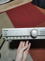
A while ago, I asked the forum some questions about a 27 I had on my bench. Specifically, whether or not the 27.5 schematics I found on this site would be of any use to rebuild the amplifier, which was shutting down quickly when the power switch was engaged. I received no answers, so I attempted to repair the amplifier by replacing a few burned components I found on the protection circuit board. Long story short, the amplifier ended up in the studio, propping the door open from time to time while I painted.

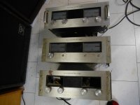
I recently decided to buy my own distortion analyzer, oscilloscope, and bench for home use, and after repairing the analyzer (an Amber 5500 that died a few hours after I turned it on), I disassembled the 27, and after taking some time troubleshooting it, managed to repair the beast. I figured I would put my experiences on the board for all to see, as no one else here seemed to know anything at all about Levinson amplifiers.

First off, to anyone else out there who may be wondering: YES, the 27.5 schematics CAN be used to troubleshoot problems in the 27. A hearty Thank you to the user who posted them here in the forums, though I cannot find the post that led me to them!

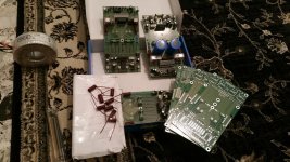
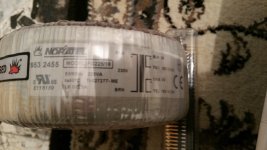
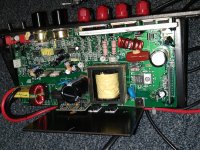
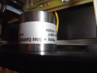
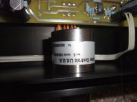
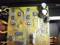
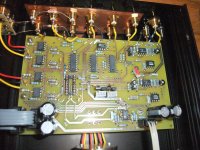
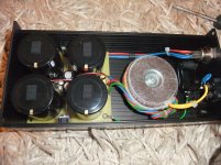
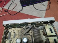
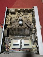
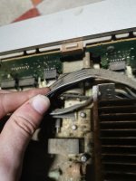
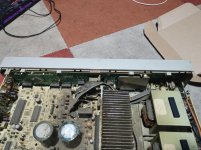
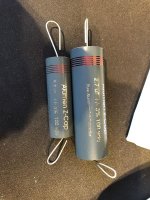
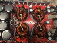
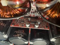
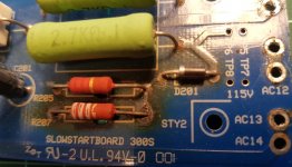
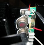
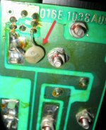
The real problem turned out to be the large electrolytic power supply capacitors, or more specifically, the corrosion on their terminals. There were other problems to be found, but they manifested themselves as poor performance rather than an outright dead amplifier. The electrolytic capacitors on the small boards hovering over the output stages needed to be replaced- they measured about 200pF each, and they are rated at 10uF. The relay coil driver had died, but that was an easy find, what with the fire and all. Associated caps around the drive transistor were found to be well off spec, and replaced.

The protection circuit was reading offset in the "bad" channel, due to the negative supply not charging at the same rate as the positive, causing a fault condition. The diagnosis was simple: After cycling the amplifier, I checked the residual voltages at each of the supply capacitors, and found the negative supply of the Right channel consistently low. Every other supply in the amplifier had charged to normal operating voltages. The second clue that I wasn't looking at an output problem was that while the rail stayed low, it didn't draw excessive current, nor did it discharge quickly after power was removed, even though the voltage was low.

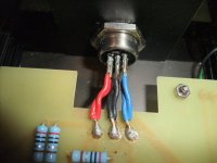
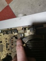
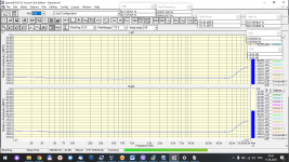
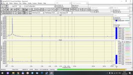
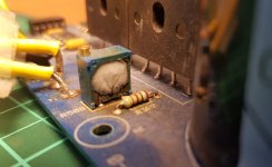
The capacitor had what appeared to be electrolyte leakage, but unusually, it appeared from inside the screw terminal. Inspection revealed no perforation. The ring terminals had subsequently corroded, and the rectifier lead wasn't able to deliver sufficient charge current in time to outrun the protection circuit. The result was a "dead" channel. After cleaning the terminals, I put in a temporary cap, and the amplifier powered up immediately. The next day, I checked the "bad' cap, and it tested very well, so after cleaning, I reinstalled it. As of today, the amplifier has run for ten hours without incident, and easily met its published specifications under test, giving me 128 watts per channel into an 8 ohm load with both channels driven.

Potting a 1kVA transformer to eliminate buzz

So after 10 otherwise happy years I'm finally sick of the humming from my high power variant of Aleph-Xs and currently looking at potting them myself to dampen the hum. It's not a loud hum/buzz but enough to be annoying in an otherwise quiet room.

I've gotten to this point after a few attempts playing with DC blocking. Originally the amp had 2x 4700uf caps with 2x diodes in antiparallel. I played around with a different variant of DC blocking circuit today this time with significantly larger capacitance and a bridge rectifier ala Bryston's circuit, but nothing changed in the slightest which makes me thing it's not DC. Also it buzzes all hours of the days in all houses I've lived in over the years. One amp has always hummed louder than the other which makes me think it's a construction issue with one transformer in particular.

So to the question:
Does anyone have recommendations as to how to pot these things?
We're talking about 1kVA 240V primary 2x 20V secondaries.
I don't have a vacuum chamber, and I'm looking to keep this experiment cheap, since if I wanted to spend a couple of hundred EUR I'd just buy new transformers.

Step response ringing

I posted these in my AINOgradient thread but so far discussion is minimal,

What is the importance of ringing in impulse/step response of a transducer?

I measured two dynamic coil drivers and planar/ribbon B&G Neo8-PDR in dipole minimal baffle. Responses, distortion and decay are naturally different but not much,

Here are ETC, impulse and step responses (ne-95 different polarity)

ETC is fastest for Neo8, but it has ringing Step response - Wikipedia, the free encyclopedia
The phenomena of oscillation about final value is called ringing. The overshoot is the maximum swing above final value, and clearly increases with μ. Likewise, the undershoot is the minimum swing below final value, again increasing with μ. The settling time is the time for departures from final value to sink below some specified level, say 10% of final value.

381442d1384076119-aino-gradient-collaborative-speaker-project-etc-audax-bg-vifa.png

381444d1384076119-aino-gradient-collaborative-speaker-project-step-audax-bg-vifa.png

Help! New to RPi streaming and in over my head

Hello all. A couple weeks ago I finally had enough of my music either
1) disconnecting from my phone thus losing control while the music continues to play or
2) dropping out completely
while listening to Spotify, Qobuz, or Tidal through my Chromecast Audio. After a bunch of research on other commercially available plug-and-play options, and realizing that, even on the used market, there was nothing that offered both reliable connectivity and very good sound quality for less than $300. I'm on a budget and it seemed crazy to me to spend $300 for a used Bluesound Node 2 when I bought my CCA for $25 and it worked well for quite awhile...until Google stopped selling them. At which point they also apparently stopped truly supporting the software integration with the streaming audio services. I digress...

So anyway, after some encouragement from others over at AudioCircle, I bought a gently used Allo DigiOne player. As most of you here probably already know it's a streamer built on the RPi 3B+, using Allo's DigiOne I2S-to-SPDIF output HAT. I plan on converting the Coax digital out from the Digione to Optical SPDIF using my iFi SPDIF iPurifier, and feeding that to my JDS Labs OL DAC (which is also on my list to be upgraded later this year).

I have plenty of experience with the analog hardware side of DIY audio, but all of these questions about Pi OS software and how it works with Spotify or Tidal has my head spinning. I’m a Mechanical Engineer and consider myself fairly “tech savvy”, but on the other hand this is my first foray into the SBC world, and I’m certainly no programmer.

I don't have any locally stored files to play; I only want to use the DigiOne for wirelessly streaming Spotify and either Tidal, Qobuz, or another lossless streaming service to my stereo. I plan on using my iPhone 6s to control. My wife has an Android, and she definitely will want to be able to stream with her phone as well without a huge learning curve. If it makes it easier, I might be open to getting a cheap Android tablet to control this all (in lieu of the phones) but I definitely don't want to add another monthly payment for something such as Roon or Volumio Premium. From what I’m reading I need something called BubbleUPnP to use Tidal (or any streaming service other than Spotify). Does that get installed on the control device (my phone in my case), or on the RPi?

What is the best OS for the RPi in my case? Volumio? DietPi? Moode? Daphile? Something else? How do I use it and how does I actually get it to stream music from Spotify and Tidal? 😕 I know I have to download the OS image file on a regular PC and copy it to a MicroSD card, which is no problem for me. I just need a beginner’s guide that compares the various OS options and gives instructions on how it all works together, which I still can’t seem to find after lots of googling.🙁 I’m really confused about how to actually get this up and running, and very close to throwing in the towel on the RPi and biting the bullet and getting a Node 2 or a Paradigm PW Link or something similar.

Maybe it’s I’ve over-complicated it all in my head. Certainly wouldn’t be the first time I’ve done that.

Help!

Thanks in advance,
Kevin

Bridging a Monster PL700B

Hi Folks;
I am considering rebuilding a couple of Phase Linear 700B's and bridging them to drive a pair of large LF cabinets. One of the two wrecks pictured was revived and produced over 430 Watts per channel into an 8 ohm dummy load.

I have seen rebuilt PL700's produce 450 Watts. The 5 Amp rail fuses held and yet this calculates to 7.5 Amps through 8 ohms. Is this because fuses open due to heating and each rail fuse conducts for only have of each cycle?

These amplifiers are traditionally 'temperamental' but I would like to try some testing in bridge mode. My first assumption would be to verify output transistor current sharing before subjecting it to the higher current demands of bridging.
Question; Can anyone suggest a procedure for testing current sharing?
Thanks, Peter in Canada

Attachments

  • Pile of PL's.jpg
    Pile of PL's.jpg
    818.8 KB · Views: 137

Electrostatic Speaker and Amplifier Clipping

Hello, I have a pair of Martin Logan SL3 with an Advance Acoustic Map-407 amplifier. The problem begins with my old Technics SU-V9 amplifier when at reasonably high volumes when a high frecuency was played the amplifier instantly made clipping and shut itself down being an extremely dissatisfying problem. So I thought that it was power handling problems so I bought a monstrous Advance Acosutic Map-407 (400 watts per channel in 4 ohm) (ML SL3 have 4 ohm) so I was happy then I’ve put a song that i always use for testing speakers (Private Investigations from Dire Straits) and when the best part of the song begins with the cymbals and drums are punches AGAIN! the amplifier get clipped and shuted down the sound at the same volume that the Technics made.

It’s extremely frustrating and I can’t find the problem so I’m begging for help to solve this problems.

My question is.. Where the hell is the problem??

Lepai 2024A+

I want to replace the volume control in my Lepai LP 2024 A+. I know it's 20K but it's an odd design, so I'd like to replace it with one that can be put in with minimal problems in terms of placement. I have no idea what brand or model it is. Does anyone know? In the process I'd like to get a better one than the one that's stock.

Thanks.

Amanero firmware or design issue or something else

I'm experiencing the issue with cracked sound in one channel of my DAC (thru Windows Direct Sound only / ASIO is OK).
Left channel sounds distorted at the Windows Default Format Test tone when I select greater than 16-bit/44.1Khz sample rate. Right channel is OK.

I've localized the root cause is Amanero USB input +- Direct Sound.
(1 it is not the Windows driver - the same thing happens on diff PC/Windows7/10;
2 not the AK4137->D/A->Analog path - because it sounds good when S/PDIF input AK4118 gets used)

I've already tried to flush bunch of different Amanero firmwares
Amanero Technologies
The results are all basically the same: either there is no sound at all or there is same issue.

The Amanero USB receiver is 100% original - got it from from their .com.
I have the AK4137 (and whole DAC) clocked asynchronously from its own master clock.

Well ... via ASIO/WASAPI everything sounds and measures OK. Just the Direct Sound via USB and one channel.

Stepped on the rakes 😉 Gentlemen, need some advise/clue/hint from you.

Thanks in advance!

Update RCA on PCB: worth it?

Hi,
I hope this is the right section.

I have a Raspberry Pi 3b+ with this digital board:
AUDIOPHONICS Digipi+ PRO Digital interface WM8804 for Raspberry Pi - Audiophonics

I'm using coaxial output and I'm very satisfied with sound (the DAC is Loxjie D30, amplifier is Advance Acoustic X-i60)

So I'm considering to add a new RCA socket for the PCB above.

Audiophonics itself suggest those:
ELECAUDIO ER-106 Inlet RCA for IC Gold Plated (Pair) - Audiophonics

In your opinion, it is worth it? A socket like this can improve the sound?

Second, it could cost me, 16 euros (I paid the board 22, so a little expensive)

I found an Ebay what I consider a clone:
1 COPPIA D'ORO RCA PIN JACK Donna scheda di circuiti stampati socket AV A/V Connettore Presa | eBay

It should be okay with the digital board?

Many thanks

Please help identify connector type

Can anyone please help identify this connector type?


It's from a USB-A to this connector cable that is for charging a foot file machine (remove foot callous skin) via USB.


One side of the connector has a notch / key in it.
Pin pitch (centre to centre) is 6mm.
Wire is marked as 24 AWG.


I'm not really sure what to search for on Mouser / RS Components to get a replacement.

Attachments

  • Screenshot_20210428_100117.png
    Screenshot_20210428_100117.png
    276.6 KB · Views: 91

Problem with NN5532 based 2.1 preamp

Hey guys,
So I want to put a subwoofer in my car, but also use the subwoofer at parties. So for that I got this 2.1 channel preamp board with low pass filter:
CIRMECH 2.1 channel subwoofer preamp board Low Pass Filter Pre AMP Amplifier Board NE5532 low pass filter bass preamplifier|Amplifier| - AliExpress

And a TDA7498E based AMP in BTL mode:
CIRMECH TDA7498E high power digital power amplifier board 2.0 HIFI stereo 160W*2 support BTL220W DC12V 36V|Amplifier| - AliExpress

Tested this with a 4 ohm 10 inch sub in my apartment and everything seemed fine.

Then I go to the car and wire it up, and also use a 24V step up to power the preamp and amp.
I have a bluetooth adapter that I use, the schema is as follows:
bluetooth adapter -> 2.1 channel preamp -> car stereo aux (from full range output) & subwoofer amp (from sub output)

In the car stereo I got a whine/white noise even with no input connected to the preamp. When playing music, the sound was mostly low end, and the highs were lost. I figured it was a ground loop issue, so used this isolator:
XH M372 Stereo /Audio Isolator Vehicle Common Ground Suppression Interference Noise Isolation Module Transformer Coupler|Integrated Circuits| - AliExpress

Used this between the preamp and the car stereo. It seems to mostly work, there is still some noise in the car stereo, since I left that on high volume to use the preamp volume. But now, I do get more high end sound, but the low end is mostly gone, and only the subwoofer is doing work, which doesn't sound that good. Connecting the bluetooth adapter directly to the car stereo aux yields much better results.

The question is, what can I do to improve the sound quality of the car stereo after it has been wired to the preamp?Can the groun loop isolator filter the low end also?Should I use some sort of power supply isolation or something?

I also kept having problems with the XH2.54 sockets, since I don't have that exact connector, and instead had to DIY a 3.5mm jack with some other connector, and it isn't quite that stable in the XH2.54 sockets of the preamp, and since it's a DIY cable it isn't shielded, could this cause any issue?

Any help could be appreciated, thanks.

Shindo MAZERIS BELLEVUS MODEL 454-2xAttenuator-How works this Circuit? 6067+12BH7

Such a circuit for a line pre-amplifier I have never seen before.
There are two negative feedback loops from the output:

1) One of the input of the last stage (470 K)
2) One to the cathode of the 6067 - first stage (100K+220K parallel in series with 2uF capacitor)

It looks a bit like a NDFL

The following questions arise for me to the attached schematic diagram (drawing and measure errors are not to rule out):

1) What is the aim of two volume controls (one on front site and one at the rear panel) ?

2) What is the name of the circuit topology behind the second volume control
(last two stages with 12BH7 - at fist look a SRPP, but it isn't)?

3) The second volume control is inside of the globale NFB loop. Which consequenses are to expect in case of the different attenuator positions there?


4) The couple capacitor in front of the second volume control is a Sprague ceramic disc with a diameter of approximately 1 inch. What could be the advantage?

about
http://www.hifido.co.jp/KW/G0103/J/0-50/C05-25468-61439-00/
you will find some pics about this preamp.

Attachments

Weird results with REW and phase

I've used Room EQ Wizard to make gated driver measurements for XO simulation (with acoustic timing reference enabled since I'm using a UMIK-1)

Using the old trick of measuring the drivers in parallel, I can find the woofer delay by adjusting Z-offset in VituixCAD until the responses match up.

Normally you would off course convert the responses to minimum phase when doing this. But here I only get the correct results when not converting to MP, and whats more, when converting to MP the responses will match up with woofer delay = 0.

In other words, completely backwards of what I would expect :scratch2:

Attachments

  • non-minimum-phase.png
    non-minimum-phase.png
    437.1 KB · Views: 146
  • minimum-phase.png
    minimum-phase.png
    445 KB · Views: 138
  • Screenshot 2021-04-29 at 20.26.24.png
    Screenshot 2021-04-29 at 20.26.24.png
    333.8 KB · Views: 127
  • Screenshot 2021-04-29 at 20.26.45.png
    Screenshot 2021-04-29 at 20.26.45.png
    403.8 KB · Views: 134

FS: Several items; OCXO Clock, cables, capcaitors, tubes

Hi, Ive got several items for sale:

Pink Faun OCXO clock 20Mhz, intended to be used with their USB/I2S/SPDIF cards. NEW - 675 EUR, my price 475 EUR shipped and paid.
Like new condition. I purchased ultra ocxo from PF, that is why I sell this.

Pair of Jupiter VT 15uf / 100V capacitors, sound like a combo of Duelund CAST and Jupiter CU, much better price than these. Downside- they are super big in size.
Price: 65% of list price from hificollective.co.uk (please remmber to add VAT to compare)

Quad of Sylvania 6B4G, purchased as NOS, still in boxes and original "wrap".
I purchased them for around 600usd two years ago, did not test them as I dont own tester. My price - 450 EUR shipped and paid


Graphite 6mm turntable matt, thick, audio tekne style. Purchased in Italy from audio tekne distributor.
Shipping only within EU, 130EUR

Paul Carmody's "Hitmakers" Lacking treble. What to do?

I've just finished building Paul Carmody's hitmakers, using crossovers and drivers sourced from Meniscus.
Prior to these, I had been using Presonus Eris e5, but I wasn't very happy with them. I'm sure they're great for mixing, but I wanted something a little more fun, a little more hi-fi.

I'm doing my first listening tests of the hitmakers (driven by Modulus 86 Monoblocks, fed by SMSL SU-9 DAC). I enjoy them, as I anticipated, more than the Presonus. They have lovely bass extension and a nice punchy midrange. Much more "musical" than my previous monitors.

But they seem to be lacking in treble "sparkle". Using a tone generator, I found that they only extend up to about 16.7kHz. The Presonus extended up to 20kHz, and I can hear well into the 18kHz range.

Is the perceived lack of treble "sparkle" with the hitmakers due to the limited treble extension? Is there something to be done about that? Different tweeters perhaps? Or is this a situation where adding an external tweeter might be of use, like a "super tweeter"?

What do you think, gang?

  • Locked
Let's help Ruth and Dave

Without Dave's release date in mind and knowing that the world stops for no one, maybe it's time to help them out.
Thank you.

https://www.gofundme.com/for-ruth-dave

EDIT: Here's what I am going to do:
I will match all donations up to the $5,000 mark as I don't think that is anywhere near enough to cover the costs of what's to come. Since they have found themselves in a position of no fault of their own, I encourage you to join me and support this.
Thank you.

EDIT2😛aypal: one of our Mods has offered his account and will accept the payment, forward that via his card to the donation site and name the donor, if you so wish.
carolinaudio@gmail.com

Adcom gfa-555II problem/question

First I'd like to thank you for taking the time to read my post. I became a member here today because my Adcom gfa-555II has recently broke and I need advice as to what I should do with it.
I have enjoyed this amp for years and it always sounded great. A couple years ago the left channel seemed to kinda fade. It worked but the sound was very low. About that time I moved and the amp has been in storage untill recently. When I hooked it up this time I heard a pop come from the left speaker and then nothing. The left channel is now dead. I could not get one of the fuses out of the back of the amp. I guess it was cross threaded. Since I have no knowledge of electronics I took it to an audio store near me. They specialize in high end equipment and have their own tech/repair business. I recieved a call yesterday telling me that the fuse that was "cross threaded" was a 20amp fuse and that it was a big problem. They told me that the amp needed a new fuse holder installed (forgive me as I have no idea of the proper terms) and a new power supply. Just for starters. There could me more problems once the power supply is installed. I was quoted $350-$450 for the power supply and fuse holder.

I have no idea if I'm getting ripped off or if this is reasonible. I'm torn as to wether or not I should fix this amp that I love or try to buy another one. After reading a lot of posts on here it sounds impossible that nothing else could be wrong. Would the power supply make the left channel play at a lower level than the right? And then finally blow? I did take the top off the amp before I took it in and everything looked fine. No burn marks on the board, no leaks any where and the big blue capacitors looked fine. I know you can't visually diagnose the problem. I guess I feel like I might be getting ripped off and I'm not sure what questions to ask the tech. What should I be asking? Is it impossible to check the other parts before putting in a new power supply?


I hope I don't sound to scrambled here but honestly this stuff is way over my head. The price they quoted me just seems high considering that there could be other problems. I could sure use some advice.


Thanks,

Brian

What to do with these M-Audio bass modules????

I picked up these M-Audio bass models for $100. I think they originally retailed for something like $2.5k for the pair. Clearly not worth that but nicely made and hella stout. Separated from their tower brothers somewhere along the way. I know there is a lot of negative karma around these being a Monster product. Probably good up to 300ish Hz.

Any fun ideas what to do with them? I could build an array. I think that is what they originally came with. I have some beat up electrostatics in the junk pile, Accustat I think. I could take the existing bass unit off those and replace with the M-Audio. Or I could use a nice, but bass limited, small speaker up top. Either acquired or made from scratch.

Just fishing for fun ideas. Any thoughts?

John

Attachments

  • PXL_20210429_234818319.jpg
    PXL_20210429_234818319.jpg
    991 KB · Views: 117

Crown Macro Reference O/P Help Please

Hi All,

I've visited & enjoyed this site a lot over the years but this is one of my first posts. Hoping I can seek some advice on output transistor selection.

I've inherited a Crown Macro Reference amp, Esoteric version with previous repairs & problems with one channel not working. The previous repairman replaced some (not all) of the original Crown C7065-3 & C7901-9 o/p's with MJ15022/23's & replaced 2 of 4 drivers with different parts as well. In addition, new emitter resistors for the MJ15022/23's with 10% instead of factory 5% units. Upon receiving the amp, I found one of the replacement drivers was not even soldered, yet the previous tech claimed it worked fine on the bench! I soldered the driver & the amp actually came to life! However the channel module is really is a dogs breakfast with 4 different o/p's, 4 different drivers & 2 different emitter resistors. 😡

Even though it is currently working, I don't trust it & want to repair properly. The Crown manual notes the C7065-3 as (MJ15004) & C7901-9 as (MJ15003). My question, are MJ15003/4's really adequate given the amp has 140v Rail to Rail? Output stage is a grounded Bridge with 3 pairs of o/p's for each half bridge. The amp is rated at 760w@8, 1160w@4 & one source states 1500w@2 ohm per channel. Yikes! that's a lot for those MJ15003/4!

Should I stick with MJ15003/4 or go to MJ15022/23 or even MJ21194/5 as many in these forums have suggested for other members repairs & projects? My apologies for the long post as I want to provide plenty of info & really appreciate any advice. FYI, I am an electronic tech, just don't repair Power amps for a living, only for myself or friends. 🙂

Strange used tube behaviour - 829B

I recently bought three 829 tubes off thEbay, and when they arrived I found that they were in worse condition than indicated by the seller. The seller refunded my money so I have no beef with them.

However, I am perplexed with the tube behavior.

All three are USN 829 tubes (not B version).

All three have good filaments.

All three get warm when the filaments are driven.

All three show no getter flash.

I expected the tubes to be gassy. However, they don't draw excessive current.

I biased them with a 470 Ohm cathode resistor, Zener regulated 180V on the screens, and 100K grid to ground resistors.

My NOS versions come up at 30mA cathode current for a bias voltage of 14.2V. Close to what I expected.

However all three tubes I received have zero emission! Nothing! Va = 300V, VG2=180V, the voltage across the cathode resistor is below 20mV which indicates less than 42uA current through the two sections combined.

Can anyone explain this to me?

Sumo polaris Mosfets needed

Hello members of diyaudio,


i know i am looking for the needle in the haystack but i give it a try.


i own one Sumo Polaris power amplifier that needs new output transistors


original mosfets are


2sj115 / 2sk405 they are obsolete


they can be replaced with:


2sj200 / 2sk1529


or


2sj201 / 2sk1530


there are 4 mosfets per channel 2 x 2


therefore i need 4sj and 4sk matched 2 x 2


if anyone can provide them please dont hesitate to contact me.


thanks in advance

Klipsch Sub-12 repair

I know this is a long shot but does anyone have experience repairing these? I combed over every inch of the board for hours and I see no noticeable burnt components. Voltage on the top of the two regs measures a little over 25.5 volts. I think it's supposed to be 30v (+15 and -15) but a video I saw on youtube makes me think it's within tolerance. I'm only getting like a half volt measuring between the legs of the two big pink resistors. It's my understanding the board sticking up in the bottom right corner is what takes +-15 and gives 5v between the big resistors? Any ideas? Thanks.

Attachments

  • IMG_20210417_134826590.jpg
    IMG_20210417_134826590.jpg
    1 MB · Views: 109

Anybody try these materials for DMLs?

I was just looking for possible materials to use for DMLs at my local Home Depot. I spotted these. Anyone ever try making a DML out of any of these materials? What were the results? All are links.

DUROSPAN GPS R5 4 ft. x 8 ft. x 1.06-inch Graphite-Enhanced Expandable Polystyrene Insulation Board

SilveRboard 24-inch x 1-inch x 48-inch R5 Radiant Acoustic Insulation

3/4" EPS Rigid Insulation

1/2" Rigid XPS Insulation

3/8" or 1/2" Drywall?

What other interesting/different materials have you tried and what were the results?

Orion T600 "The Hot Setup" no output

Another Orion stumper for me. This amp powers with 0.6A idle and has good +- voltage everywhere, almost. It will sometimes play a little out of the left channel at first power-up, but starts to get clamped down and goes mute. The right channel plays nothing.

Theres an opamp in the middle of the board that I replaced, because I was finding close to regulated supply voltage not only on the power pins, but also on the output pins. I replaced the JRC4562D with a spare TL072. I notice the DC voltage on output pins climbs as the amp stays powered on for a few seconds. All input pins are at 0vDC. Regulated voltage is about +-14. All other opamps are either at close to 0vDC or +-14vDC on pins, IE correct.

All diodes seem to be testing OK in circuit. Same for the MPSA06/56.

This amp is Orion built but not sure how similar this is to other more popular Orions. Its simplified compared to some of the SX line I've been working on. This one was built in 1997. For BestBuy is my guess.

Thanks ahead, if help is available.

Pics next post.

Horch 1.2 P&G - one of German's best sounded Pre-Amplifiers. Schematic wanted

Who can upload schematics ?
In the attachment various images around the PCB and outdoor power supply
P&G website is dead - go to
Penny + Giles - Rotary Potentiometer

Attachments

  • DSCF7016.jpg
    DSCF7016.jpg
    1,008.7 KB · Views: 530
  • DSCF7030.jpg
    DSCF7030.jpg
    979 KB · Views: 506
  • DSCF7028.jpg
    DSCF7028.jpg
    983.2 KB · Views: 494
  • DSCF7026.jpg
    DSCF7026.jpg
    1,023 KB · Views: 504
  • DSCF7024.jpg
    DSCF7024.jpg
    1 MB · Views: 576
  • DSCF7022.jpg
    DSCF7022.jpg
    992.6 KB · Views: 307
  • DSCF7020.jpg
    DSCF7020.jpg
    1,010.6 KB · Views: 275
  • DSCF7018.jpg
    DSCF7018.jpg
    979.2 KB · Views: 282
  • DSCF7036.jpg
    DSCF7036.jpg
    1,023.3 KB · Views: 273
  • DSCF7056.jpg
    DSCF7056.jpg
    979.7 KB · Views: 274

Threshold Stasis 2 Bias Help Extremely Sensitive

Hi guys, looking for advice. I have a Threshold Stasis 2 in for repair. The amp arrived working, but absolutely cold to the touch, even after several hours of use.

I tried to adjust the bias and it is extremely sensitive. Turning the pot clockwise, even a fraction of a fraction of a millimeter, emitter voltage jumps to 500mV, 1V+, etc. Turning it the other way, same story, 50mV, 0V.

I replaced the 5K bias pots on both channels and all of the electrolytic capacitors. But the sensitive bias adjustment remains. I cannot get the amp to the proper 50C temperature. It’s either too low and cool to the touch, or jumps dangerously high. It’s so sensitive that just inserting a small screwdriver into the bias pot (without turning it) is enough to drastically change the adjustment.

The amp produces good sound and I can’t see any other problems. Any help is greatly appreciated.
  • Like
Reactions: TheFinisher

EL84 safe plate voltages

I'm measuring plate voltage on a PP amp with EL84, and when turning on Vak jumps up to 380V before falling and hovering around 300V. According to the datasheet, 300V is the maximum value.

I'm concerned that the tubes might be quickly worn out, or start arcing. However, when searching around, it seems others are (for example) using plate voltages in excess of 400V on other kinds of tubes with the same voltage ratings (12AX7 for instance) 😱

I understand that some brands might be more forgiving, but aren't maximum spec maximum for a reason? Is it common to drive tubes so hard? What rules of thumb are there, and when should I worry?

Zed Audio question

I visited Zed's site for the first time and found on the service page :
The brands we choose not to repair are Memphis, MATTS and USAmps.

Anyone know why? Im just curious. I have much respect for these guys as some of the best amp designers out there so this kinda got me as own several Usamps and thankfully none of them have ever given me an issue. I have always looked at MATTS as being good quality amps, I dont have much experience with Memphis other then I used to see a lot of there 4k monsters getting sold on ebay for parts or repair.

How easy to install a KSS-213C mechanism?

Maybe a bit of a novice question but I have a Yamaha CD player that is temperamental at reading discs due to a weak laser, I think, and have a brand new Sony KSS 213CCM mechanism(complete with a brand new laser) to replace the old one. I was wondering how easy it is to remove the old mechanism and fit the new one, and how much disassembly is required? Pictures of the internals of the Yamaha player can be found at the link below, to give you an idea, so any tips on how to approach things would be appreciated. The cost of taking it to a tech to do far outweighs the value of the player, so thought this might be a good one to start on some DIY for myself (wont be losing much if I kill it completely!).

YAMAHA CDX-E100 : ???????????

Markaudio Alpair 11MS pensils "skipping"

Hi -- I just finished building a pair of pensil cabs with Markaudio 11MS drivers to go with the ACA I recently built. I took them for a test run. They sound amazing. The only problem is when I walk on the floor near them, especially when walking hard, they "skip," meaning that the vibrations from from my feet are enough to make the cones move further in an out then they are supposed to, causing them to misfire and making the sound go off. I have wood floors and no isolation pads or spikes on the cabs yet. I tried some foam isolation pads but they don't help. I'm considering adding spikes, if you think they will help. My kids and I like to put on a records and dance around the living room, which just won't be possible with these speakers unless I can find a solution. My previous speakers were bookshelf speakers on stands, but these cabs are way too big for stands in my small living room. Any thoughts beyond adding spikes? Is it because these drivers don't have a traditional spider, so move in and out more easily?


Thanks for your thoughts and advice! Now back to listening to some records (but not dancing to them). 🙂

F5 Turbo V3 - Help with uneven bias on N Channel

I'm at a loss with one of my F5 Turbo monoblocks. No matter what I try, I cannot fix a serious imbalance of the bias on the N-channel of one amp.

Let me start by saying that I have tried three sets of matched MOSFETs in the N-channel and replaced all the source resistors with 1% wirewound. But this has not stopped the voltage across the source resistor on the first MOSFET on the first n-channel board from being at least double the two MOSFETS on the second n-channel board. (The second MOSFET on the first board falls somewhere in between.)

If you assume the MOSFETS are properly matched and there is no major imbalance in the source resistors, what, if anything, could be causing this? I have tried changing the tightness of different mosfets and it makes only a small difference. The voltage is consistent across both boards (-40.6)

The p-channel is fairly closely matched across all four mosfets (within 20mv or so).

Any thoughts or creative ideas would be appreciated.

Cascode SIC Fet for Class A VAS

Hi,

I just recently came across SiC FETs from UnitedSIC. These SIC FET devices consist of a Si MOSFET with an embedded SIC JFET in a cascode configuration. I found these might be an interesting alternative for single ended class A voltage amplification stages. I typically use an IRF610 or IRFBF30 as MOSFET with a separate JFET or MOSFET for cascoding.

Anyone who have experiences in this direction or any comments to my idea?

/Anders

How to make mulberry paper widerange cones: the biological way

Hi,


Of course I know that there are easy ways to make a paper cone, just cutting a flat piece of paper and glueing it together.

But I didn´t aim at another Lowther copy, I want strong, light exponentially curved mulberry paper cones.
So I went and manipulated the DNS of our mulberry tree (morus alba) a little bit, I think it´s now morus alba musicorum. The cones now grow directly on the mulberry tree, and are exactly as I want them.

I´m very happy with the results, please have a look at the photos.
Time to harvest!
Time to build drivers!


All the best


Mattes

Attachments

  • The Mulberry Tree.JPG
    The Mulberry Tree.JPG
    928.3 KB · Views: 225
  • Grown cones.JPG
    Grown cones.JPG
    825 KB · Views: 211
  • Grown in the light.JPG
    Grown in the light.JPG
    387.8 KB · Views: 208
  • Light reveals the shape.JPG
    Light reveals the shape.JPG
    457.8 KB · Views: 213
  • Time to harvest.JPG
    Time to harvest.JPG
    442.8 KB · Views: 207

LM3886 with small modification sounds amazingly good

Some years ago I built two mono LM3886 power amplifiers but untill now I didn't use them. I decided to change my old amplifiers, self designed and built in the late 70's, for these ones. I am suprised by the amazing sound quality coming out of my two Audio Physic speakers (4 ohm).

The small modification is quite simple. I omit the electrolytic capacitor in the feedback loop. Then there will be a bias voltage on the output. I compensate this by a resistor to the negative input of the LM3886, with parallel a MKP and a styroflex capacitor. See the circuit.

The resistor will be first a trimming resistor, to find the value so that the output bias voltage will be 0,00 volt. Then replace it by a fixed resistor of the most nearby value.

I also omit Rf2, Cf and Cc, as seen in many applications, because they cause oscillations in the flanks of a square wave by a capacitive load.

I have no time to compare this circuit to the “normal one”. Will somebody do so?
img151.jpg

What Chip is inside these 2 Digital (Toslink+Coaxial) to Analog (2RCA) Converters?

Hi


If you search eBay for Digital SPDIF to Analog,
2 results that repeat themselves quite a lot are these:


The first:
Outputs 2 RCA (without 3.5mm):

image.jpg


The second:
Outputs 2 RCA and a 3.5mm:

image.jpg


As can be seen, those 2 models are pretty similar,
the only (external) difference is that the first is a little bit smaller, and without 3.5mm,
and the second is slightly wider, and has 3.5mm in addition to 2 RCA.


Does anyone here have them, and know what Chip is inside?

Also I would like to ask if there's a difference in the chip between the first and second model..
The reason I ask this, is because the second model (with 3.5mm) is about 10$,
while the one without the 3.5mm is aprox. 4$..

I assume this difference is not due to the cost of a 3.5mm socket.. 🙂
So there's a high chance that there's a difference in the chip inside..


Hopefully someone here has them and knows.


Thank you

Help needed, Technics Sa-E10 Amplifier, Volume pot issues

Hello I have a technics stereo integrated tuner amplifier Sa-e10, one of the chanels is intermittent when you turn the amplifier on it works for a moment before cutting out.

I think I have damaged the volume potentiometer as it was crackly and I sprayed it with contact cleaner to sort the issue but might have been abit enthusiastic with the twisting of the pot and damaged the contacts, it's a moterised one and I would like to open it up further and see if I can fix the issue.

I'm struggling to find how to take the front panel off properly, I can see the screws but cant work out much from the service Manuel, can anybody give me a hand and lend some knowledge?

Thanks kieran
[wiki=[wiki=]%[/wiki]]%[/wiki]

Attachments

  • 16196397468148798469459189870371.jpg
    16196397468148798469459189870371.jpg
    708.8 KB · Views: 285
  • 16196397328557903967956310994543.jpg
    16196397328557903967956310994543.jpg
    990.7 KB · Views: 220
  • 16196397796496296243099047875607.jpg
    16196397796496296243099047875607.jpg
    501 KB · Views: 294
  • 16196398011711876712513544994545.jpg
    16196398011711876712513544994545.jpg
    352 KB · Views: 240
  • 16196398280589135150654391637404.jpg
    16196398280589135150654391637404.jpg
    617.7 KB · Views: 190
  • 16196398675184322051255150390055.jpg
    16196398675184322051255150390055.jpg
    389.2 KB · Views: 158
  • 16196398821528903195932988672590.jpg
    16196398821528903195932988672590.jpg
    349.6 KB · Views: 162
  • 16196399116814948042707914371126.jpg
    16196399116814948042707914371126.jpg
    889.9 KB · Views: 199

XLR/RCA plugs - How to wire connects?

Connecting a preamp with RCA outputs to a Yamaha P220 power amp with XLR inputs.

The Yamaha doesn't possess, apparently, genuinely 'balanced' inputs.


With regard to soldering the lugs onto an interconnect, a couple of questions:

On the XLR plug...
Positive is soldered to pin 2,
Ground is soldered to pin 1,
Braided copper shielding is soldered to pin 3. Pin 1 and 3 are connected with a short soldered wire.

Question 1.

Is this wiring correct?


Question 2.

On the end with the RCA plug the positive lead is soldered to the pin but ...should both the shielding copper braiding and the ground wire get soldered together onto the ‘sleeve’ part of the RCA plug? (Or should the copper braiding be left unattached to the sleeve?)

please recommend replacement transistors

I have a broken C3519 and A1386 pair from Sanken, which are in an Onix A-120 amplifier. (I like the amplifier, though I think the 2dB boost below 200hz is an undesirable "feature")

I am looking for replacements.
Apparently the 2SA1294/2SC3263 and Toshiba 2SA1302/2SC3281 are suitable pairs to replace them, but I would like to know what options I have for "upgrades" to the transistors. I am willing to purchase two pairs, and anything less than $10 per transistor is worth considering to me. I also don't different physical shapes, as I can use thermal adhesive to attach them to the sink.

Would you need to know more about the circuit design to pick a suitable replacement? The amplifier is rated for 120watts into 8ohms and something like 150-180watts into 4ohms.
Can I increase the amps tolerance for lower loads, reduce distortion, or make other improvements with different transistors?

mtx 1501d

repairing a blown 1501d read earlier threads and found 75339p transformers at mouser.com i need to know if anyone knows the size of resistor near the first transformer locations R435 and R436 i cant read the numbers on mine if anyone has a 1501d and wouldnt mind takeing the cover off and letting me know these i would greatly appreciate it

im new at this but do have some knowledge with electronics

thanx

Help - uMar-KenSETWoofT WAW / FAST

Hi everyone, looking for some advice and help.

I'd love to build a set of uMar-KenSETWoofTs. I think they look amazing and have always ogled over the pictures p10 published years ago of the uFonkenSET. I want to do similar with the Alpair 5.3's.

uFonkenSET-matched-woofT.jpg


I have the skill from a woodwork perspective and i've built a few sets of speakers now (including ones needing XO) but i've always followed plans to the letter. I have zero speaker design skill which leads me to two main questions.

1) do all the dimensions/port spacings stay the same with the update from A5x planset using 5.2 drivers now we are up to 5.3? (Dave - hoping you can chime in here)

2) I am clueless with how to set up the WAW/FAST system. Is there a plan 'to follow' like the cabinet builds so I can blindly copy and know there will be a successful outcome at the end...? I'm probably going to go with the Peerless 830870 drivers for the WoofT

Thanks in advance for any help anyone can give!

different sized Jantzen caps

Just in case somebody wonders about different sized Jantzen caps. There seems to have been a design revision for der MKP-Z series caps.

This was mentioned earlier in a closed thread:
https://www.diyaudio.com/forums/parts/332870-fake-jantzen-caps-hifi-collective-2.html

And I ran across the same issue now with Alumen-Z caps (see pic attached). I do believe they are original parts. But it erodes a bit the trust, when not even the dealer is informed about such changes. I am an engineer and have some experience with such "optimizations" myself. There should always be a customer info explaining the changes, when they are made.

Attachments

  • alumen 2,7.jpeg
    alumen 2,7.jpeg
    60.1 KB · Views: 132

USB ADC on Cirrus Logic CS5381

Good afternoon!

Finished the audio ADC on CS5381.

Connection interface: USB only.

The input buffer is made on an FDA op amp, so you can connect both balanced and non-balanced sources. Recording formats: 24-bit 44.1 kHz-192 kHz.

Powered by USB, current consumption 750 mA.

A pair of images: a noise shelf and THD, the source of the Victor generator at 1 kHz. The input divider -12 dB.

There are certain problems due to the low input resistance, so it may be necessary to recalculate the filter, which may cause a slight deterioration in THD

Attachments

  • 20200811-01.png
    20200811-01.png
    183.4 KB · Views: 818
  • 20200812-01.jpg
    20200812-01.jpg
    382.2 KB · Views: 763
  • 20200811_1412181.jpg
    20200811_1412181.jpg
    310.2 KB · Views: 826

300B SET Amp recommendation

I'm a longtime audiophile and over the last 18 months have been doing more DIY projects. I now have a half dozen projects under my belt (no tube designs except for a tube input buffer on a class D amp) and I'm thinking my next project should be a pair of 300B SET monoblocks.

My current speakers are 93db/w, but I'm working on a new pair that will be 99db/w line sources with a nice easy load impedance. These will cross over to separate active subs at around 180hz, so these amps won't have to handle the lower few octaves. So I'm figuring something in the 4-8w range will be plenty.

I'm not trying to save money by building my own - I do DIY for the enjoyment and satisfaction - so I'm looking for an amp project that will deliver stellar performance without much concern for build cost.

I'm planning to use a balanced connection, so will either need a balanced input or can add a coupling transformer.

I'm willing to consider a kit if the parts quality is high, but I'm comfortable building from scratch.

I spent some time searching this subject but the threads I found with recommendations were pretty old with mostly broken links. So I'm looking for recommendations on where to start.

Thanks,
Jay

Seeking Electrocompaniet knowledge, or maybe just general knowledge

Hello all


I was handed down a pair of EC AW-PRO 1 monoblocks from a friend. He stated there was some problem with powering them on. The plan was to service them with new caps, and finding the power-on issue. After some dismantling and inspection there clearly has been a few hotspots in them. They are remarkably similar in the burnmarks in both amps, so I'm thinking there is something fishy going on. I was given some vague info about the slowstart boards beeing retrofitted, and the soldering of mains wire on and around the board is clear evidence of such.


I have no prior experience with the brand and struggle to find any usefull documentation or schematics, other than the amp board. Absolutely none on the slowstart and PSU/sisterboard


I guess what I'm asking is if there is something obvious to start with i regards to finding out why these boards are so burnt?

Attachments

Parts identification

Hi All and thank you for letting me join.
I’m very new to tube amps but I know about
Modern Electronics and I think I should be ok,
I’m aware of working with the high voltages and safe isolation.
Would anybody have any ideas as what these 2 parts are
they are in an amp I bought with a rats nest wiring inside
the soldering was done by a 2 year old watching television.
It also comes with no wiring diagram so having to reverse eng to
try and make a schematic I can then follow and understand.

Adcom GFA555II help - What is this stuff?

Read some other threads and I have decided to replace the parts in this shopping list. Please check my math on this but I thought others might find useful. Remember I'm a real newbie on electronics. I can solder but electronics is a language I'm learning.

In the other picture there is a gray colored glue (I think) covering the transistor. What is that glue? What will I find under this glue? Is there some type of a connection the wires attach to?

Also I assume these gray capacitors are in need of replacement? Check that I have the right ones. See XLS shopping list and pic of round orange cap and pic of old gray cap.

Mucho Thanks!

Ps The quantity on the transistor that say 4 should be 8.

Attachments

  • 2021-04-27_11-11-28.jpg
    2021-04-27_11-11-28.jpg
    132.6 KB · Views: 196
  • j2.jpg
    j2.jpg
    55.1 KB · Views: 192
  • j3.jpg
    j3.jpg
    88.4 KB · Views: 188
  • j4.jpg
    j4.jpg
    61.8 KB · Views: 188
Projects by fanatics, for fanatics
Get answers and advice for everyone wanting to learn the art of audio.
Join the Community
507,758
Members
7,887,111
Messages

Filter

Forum Statistics

Threads
406,169
Messages
7,887,111
Members
507,758
Latest member
Cindy