Waveguided tweeter questions.

Hi folks,

Due to an incoming project with a waveguided DX25 tweeter within a WG148 Visaton, I'm asking myself the following questions.

-The speaker will be wide baffle. Will the width act as expansion of the waveguide, bringing it's effectiveness further to lower frequencies?
-Is it necessary/beneficial to offset the tweeter despite the waveguide to fight diffractions?


Best regards,
Alexander

New 45/2A3 amp power supply question

Hi All.

I'm starting a new 45/2A3 build soon and would like your opinions on a power supply that I have been playing with. I have attached A PSUD2 screenshot for your consideration. It will be optimized for 45, as I have a couple of nice pairs, but I would like to use 2A3 in it as well. I could do this by using a different rectifier when I use 2A3, or I could vary cathode resisters with a switch or both. Any comments or advice would be appreciated.

Attachments

  • 45.jpg
    45.jpg
    536.3 KB · Views: 671

One of these days

Power On since a log period of not use my Tek 7L12 Spectrum analyzer, and bang a problem. I couldn't turn the nice coarse tuning dial, it is barely move and jammed...

Time to open up the beast, used to calibrate and repair these guys 35 years ago... These Tek modules are so dense that it is not a work in the park to work inside them, and the spectrum analyzer are the worst!

I had to completly removed the front panel and the thousand buttons and dial, and the IF module to be able to pry open the front section wide enough to extract the frequency dial assy. Guess what I found? a little custom gear was unglued and cam apart. It was no longer turning the mechanical dial and YIG tuning pot...

Put some glue, let it tried and put it back to try. But surprise! naturally it was not working fine, dial was still difficult to rotate at some position, and jam at others. Removed it and using a magnification glass look at the little gear teeth, bingo some where slightly bent, and some other where not straight. Using a fine plier I straighten and realigned the incorrect teeth. Put it back and Voila! working like a charm again.

Attachments

  • IMG_20210502_235810.jpg
    IMG_20210502_235810.jpg
    375.8 KB · Views: 106
  • IMG_20210502_235806.jpg
    IMG_20210502_235806.jpg
    585.3 KB · Views: 98

6SN7 + 6SL7 suggested combination for Willsenton R8

Hello.
I have bought a Willsenton R8 amplifier.
I will use Genalex Gold Lion KT88 reissue power tubes and I'd like to know what kind of 6SN7 (x3) + 6SL7 (x2) shuold you reccomend me not expending more money in tubes than in the amp itself.

I have RCA 6SN7GTB that I could use... what 6SL7 for those?

Attached you will find schematic if it helps
thank you.

FS: Pair of Tweeters for Sonus Faber Cremona

Hello
I have sold my SF Cremona and I had some spare parts that the new owner hasn't bought... and I don't need them any longer.

For sale a pair of Sonus Faber Cremona tweeters (ref: TWE3001) valid for floorstanders and bookshelf (Cremona Auditor)

They are absolutely in new condition. Never used not measured.
Boxes opened just to take pictures.

Retail price is 190€ each. I would let them go for 200€ shipped to EU.

I have opened an auction at ebay, so, if interested, this is your chance.
Tweeters Sonus Faber Cremona TWE03001 (pareja) | eBay

An externally hosted image should be here but it was not working when we last tested it.

An externally hosted image should be here but it was not working when we last tested it.

An externally hosted image should be here but it was not working when we last tested it.

An externally hosted image should be here but it was not working when we last tested it.

OTL power supply advice

Hi,

I have built the OTL amp described in the thread:

HTML:
https://www.diyaudio.com/forums/tubes-valves/189282-vacuum-tube-otl-power-amp.html

As i was building it and fitting into a case all seemed fine but now it sounds awful at even moderate volume. I am a newbie to valve amps but i think the problem is the power supply, which is basically:

115v-0-115v toroid - bridge rectifier (1.2kv, 16A UF soft recovery) - 4700uf 250v in both the +ve and -ve rails and 1000uf 400v between the rails. This provides +150v / -150v.

When i turn the PS on i get +-150v at the final cap as expected but then when i turn the 6C33C heaters on the PS output drops to approx +- 40v with only 9v across the cathode resistors (was about 40v when the amp was working OK).

If i pull the tubes on one channel the voltages improve slightly.

Im guessing its the caps (Evox Rifa PEH169's) which were NOS are failing after only a couple of months of use.

Would be grateful for any thoughts / advice.

Thanks
Gav

Amp outputs for LG 55um7000 (TV) internal speakers

The LG 55UM7000PLC internal speakers are chip amp powered from the board, and my question is if this is a traditional amp - speaker setup, or if it is something else.

My reason for asking is that the TV lacks variable line out, or any analog audio output for that matter and I wanted to get a couple of rear surround channels out of it.

The way I want to accomplish this is by connecting the +left and +right from the internal speakers to the primary side of a 15kOhm 1:1 line transformer after having taken down the speaker level to line level using one 10kOhm resistor on each speaker level feed.

On the secondary side of the line transformer I choose one lead as ground and the other as signal and connect these to an external amp to get the rear surround, these will then only put out the difference between the two front channels.

The problem is that all I get is noise in the rear surround channel, so I suspect there is something going on with the internal amps output to the internal speakers, of which I get my line transformer inputs as described above.

Any ideas or thoughts on why this might be?

Please don't suggest getting an external surround receiver, this is a diy forum after all 🙂

Measurements from MTM with tweeter waveguide

Here are a couple sets of measurements I obtained using SoundQueasy to measure the response of my latest speaker project. It's really an extensive overhaul of a previous design, using the same drivers but modifying the cabinets and adding an MCM waveguide to the tweeter. The drivers are oldies but goodies: ScanSpeak d2900-9300 textile tweeter, and two Vifa 5.5" P13WH-00-08 woofers. These are the same drivers Olson used in his original Ariel speaker design some of you may remember. For historical reasons my two woofers are rather widely spaced (sorry, I have no photo with me as I write this). Given the recent interest in waveguide-terminated tweeters I thought the measurements might be of interest to someone anyway.

The top set shows the total SPL, the woofers with their crossover in place, and the tweeter with its crossover in place. The slight downward tilt in the response was done on purpose because I didn't want an overly bright response. These graphs do not include any nearfield woofer measurements to extend the results to lower frequencies, so ignore the low frequency rolloff. (In case the scales are hard to read: there are 5 dB between neighboring pairs of horizontal grid lines.)

The lower set of measurements is from on axis (0 degrees) and then increasingly off axis in 15 degree increments (15, 30, and 45 degrees). All measurements were taken at about 1 meter, and at the height of the tweeter.

The glitch in the high frequency response around 10 KHz is a bit smaller in the other speaker, but otherwise the responses of the two speakers are nearly identical. Comparing waveguides I think I might have made one waveguide VERY slightly deeper than the other. I've verified by adding pieces of tape to the waveguide that little tiny changes in the tweeter's immediate environment induce significant changes in that 10 KHz range.

In spite of the glitch I was pleased by the controlled off-axis rolloff since that was one of my main design goals. Now I'll just have to learn how to make better use of SE's crossover optimization tools. I came up with these crossovers the old fashioned way: tweak-measure-tweak-measure...

Few

MTM_waveguide.jpg

Potentiometers for the elektuur Preamp

I almost sourced all my components to build the elektuur Preamp. I just need the potentiometers dat are listed in the article.

- 10k log potentiometer: Bourns, Spectrol,...
- 10k log stereo potentiometer: Alps RKGA2-10K AX2

I didn't find that specific Alps type potentiometer and the Bourns, Spectrol don't specify a part number.

Can somebody suggest high quality potentiometers dat I can use in this preamp.

The article itself is in februari 1987 of elektuur.

EQP-KT Valve EQ mod advice please

I'm trying to improve the sound of this EQ but there are no schematics. Anyone have a clue what should be replaced for improvement? I'm mainly interested in the path of the valves. Thanks

Attachments

  • IMG_20210428_235412066.jpg
    IMG_20210428_235412066.jpg
    690.6 KB · Views: 469
  • IMG_20210428_235420670.jpg
    IMG_20210428_235420670.jpg
    636.7 KB · Views: 453
  • IMG_20210428_235424230.jpg
    IMG_20210428_235424230.jpg
    602.6 KB · Views: 421
  • IMG_20210428_235427780.jpg
    IMG_20210428_235427780.jpg
    587.6 KB · Views: 413
  • IMG_20210428_235432178.jpg
    IMG_20210428_235432178.jpg
    642 KB · Views: 493
  • IMG_20210428_235438244.jpg
    IMG_20210428_235438244.jpg
    649.5 KB · Views: 322
  • IMG_20210428_235447588.jpg
    IMG_20210428_235447588.jpg
    571.8 KB · Views: 357
  • IMG_20210428_235455293.jpg
    IMG_20210428_235455293.jpg
    529.2 KB · Views: 406

Arcam Alpha cd7se powering on and off while playing

I found a helpful thread here to change the Sony kss-240a laser when it started skipping all the time and cleaning wasn't helping.

First impressions were great, no more skipping, then after about 3 minutes the power tripped off (including the main green power light) then came back again. So it sounds good now but only lasts a few minutes before it trips. Anything I might check? I tried a different power source already, tried reseating the ribbon cables. Would be delighted to get it working again. My electronics skills are limited but I do have a multitester.

When I plugged it back in, in my haste to check the result of changing the laser, the power button was already on whereas I would normally be careful to check first. Could the elderly circuits have suffered from that initial surge?

Any suggestions much appreciated!

Cheers,

Dave

VU meter works on preamp input put but not on output....

I have a led vu meter based on the KA2284 IC. If I connect it to the preamp input it works fine but as soon as I connect it to the output of the preamp the signal level of the output drops drastically. The preamp is based on NE5532 opamp. Im a total novice, I'm guessing it's to do with impedance matching but can any experts help me diagnose the issue? Preamp board front/rear and vu meter images attached....

Attachments

  • Screenshot_20210429-140438_eBay.jpg
    Screenshot_20210429-140438_eBay.jpg
    225.8 KB · Views: 195
  • Screenshot_20210422-114354_eBay.jpg
    Screenshot_20210422-114354_eBay.jpg
    861.6 KB · Views: 169
  • Screenshot_20210422-114343_eBay.jpg
    Screenshot_20210422-114343_eBay.jpg
    332.6 KB · Views: 199

Dayton audio DCS380-4 VS. Eminence Alpha 15A: the battle of the budget woofers

I just put together an open baffle with a full range driver and only wish to add a subwoofer crossed over around 100hz on the same baffle and completely open. i already have two eminence Alpha 15As that sound decent but i just found this subwoofer with higher Qts and lower resonance frequency. I realize that 15A is really a woofer designed to cover a wider range and the Dayton is really just a sub. I will be using these (,aybe 4 of them, 2 per side) under 100hz.


the only reason that I'm opening this thread the reviews on the dayton audio are only from people with vintage box speakers. I want to know for my open baffle use with the front baffle that measures 16 high and 24 wide (meanibng that each driver will be mounted on a 16 by 24 inches panel and then mounted on top of the one below it so that the 1 full range driver and the two woofers per sinde each having their own 16 by 26 panel make up the front baffle that will be 4 feet tall), is there a reason to not go with the dayton? any 1st hand experience?

Offset driver entry (the ‘upstream ‘pipe’)why?

Why do we sometimes use an offset driver entry? And whats so significant about that location if its deliberate?

A few i use for an excuse to do it:

- the void at 3 x the Fb in the ‘TL’ is eliminated and a clear BW exists to the next void at the 5 /4 harmonic?

- that area created is often a fold and it simplifies driver entry?

- the area around the driver is often one that damping is bu e to use in and the offset driver makes it more affective as a lower pressure zone(more velocity to aid in the affective ness of any fibrous material used?

- more volume of enclosure might help acoustically and as a LPF?

But what else? I Find recently (it seems) if we do it on both sides of the cone it becomes an opportunity?!! As in the newer ‘PH’ modes of horn response. Theres a seriously powerful element in a ‘sacrificial anode’ rear chamber with an offset and stuffing strategically placed there.


What other ways is ‘offset’ used or useful that might be good to use or try and incorporate in a ‘design’?

shorted rca to main gnd

Have amplifier which gives big noise to other amplifiers when rca connected to it.
RCA (secondary ground) is shorted to the primary ground.

Not exact amplifier and schematic, but idea is the same. removed r166 and cc29 - still short. Is there some other common point where it can still make a short between these two grounds?

Attachments

  • sundown.png
    sundown.png
    515.3 KB · Views: 103
  • rca.png
    rca.png
    65.8 KB · Views: 103

Recommend cheap(er) Win media box?

I'm looking for a RELIABLE but ideally cheap(er) "TV Box" that would be used for audio and some video.

Requirements (non-negotiable):
MUST run Windows, probably win10. I know that Linux is the ultimate, but my audio interface only has win (and Mac) drivers. Yes, I know that Mac is better than Windows, but there is something to be said for a PC system that is not well into the four figures 😀
MUST have at least three USB ports.
MUST have HDMI out for video.

I was quite satisfied with a Pipo X9 for about 5 years until it died early this year. Since then, I've bought two Pipo X9S and BOTH were defective. The first the touch screen didn't work. The 2nd has severe USB issues. It's worth noting that in my first attempt, about 2015, the 1st Pipo (probably an X8) I ordered, NONE of the usb ports worked. Clearly, they have quality control issues. In fairness to Pipo's brand, I am buying cheap stuff from China: especially now, quite possibly remaindered or returned units (these date to 5-6 years old).

Technically the current one with flaky USB is working. But a 2-day old PC that boots selectively, and not at all depending upon how USB accessories are plugged in, as well as showing 100% CPU utilization when no processes are running, does not inspire confidence 😀

$200-ish is a nice price for a basic box, but I'm getting tired of the hassle of returns. Return shipping is $40+ and that's 20-25% of purchase cost lost right off the bat -- not counting many hours of useless fiddling.

Enough! Can someone suggest a cheap-ish reliable media box, not too much above the $200 range? I've yet to check, but even another Pipo is acceptable -- if seller will pay return shipping.


Please forgive the sloppy formatting. Apparently the web site's editor likes to put in extra blank lines, for its own reasons!

Are you refrigerating your solder?

I went shopping and drilling down through the options I noticed ‘shelf life’. Some spools of my seldom used diameters could date to the previous century. On occasion I use additional flux when needed. And I’ve had MOSFETs that refused to function properly until every last bit of flux was washed away from anywhere near the gate.

Could my problems be refrigeration? 😱

I have a ‘**** in my shop. A successful build calls for champagne. So when toasting, “That was a very good year …. for solder.”

Attachments

  • solder shelf.png
    solder shelf.png
    68 KB · Views: 290

Exciter's sound and helpful advice.

Good evening everyone. I hope everybody's doing well and staying safe? So am looking at replacing my dad's speakers with a exciter on a small piece of wood you can mount on each side of the tv. I am wondering how they sound? I know that they don't do deep low end. I'm looking for something more moderate that is nice sounding.. My dad only this is the background music. He never has his volume up between seven and eight o'clock and rarely at a nine on his integrated amp..Your advice is greatly appreciated. Thanks Jeff

RTi12 crossover measurements for left/right comparative

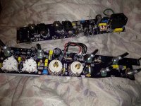
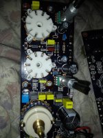
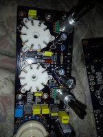
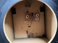
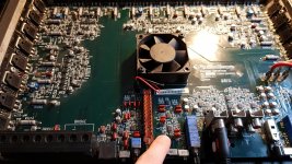
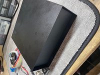
just aquired these old RTi12's.

In their place have been many varieties of speakers.

the rti12's sounded like they had remarkably bad imaging. from reading user comments these speakers should have decent imaging.

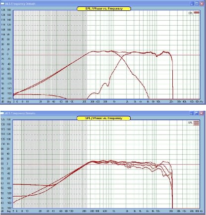
So i've taken some measurements. note am new to this so forgive errors / misunderstandings.

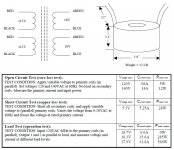
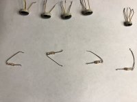
firstly had measured resistance at various points; the left speaker / side seemed to sound better. all seemed normal, variance between speakers at terminals is 0.2ohm iirc; variance between 7" drivers is 0.1 ohm. and no variance with mid/tweeter section of crossover (didn't measure that sections speakers individually)

from there measured with oscilloscope at various points and inputs.

first just to show "baseline" measures; again am new to this.

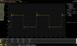
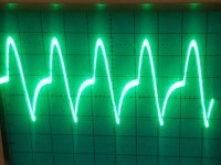
Pre-Amp with 1000hz input - both channels (Why is positive swing so much lower?)
Preamp-1000hz.jpg


Amp with 1000hz input - both channels (positive / negative differential not as big, which seems odd to me, given this is the amplified part lol, went back to verify not a connectivity issue and was not whats more both signals show this difference)
Amp-1000hz.jpg


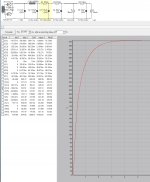
and finally Amp with zero input and both channels; note I had "zeroed" the charting with the leads not attached to anything. so this is a measure from that basis. and it sits in the negative side. perhaps that is measuring a DC voltage; subsequent-sorry am new to this and this is a "new perspective" to reading DC voltage for me. seeing electricity in graph over time..i.e thought a bit and realized just now lol can that be adjusted out? I only know of transistor bias adjustment. is there DC adjustment?
Amp-ZERO.jpg


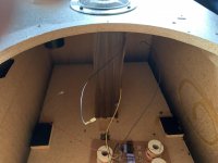
That said, imaged below is zero input measured at connection to midrange speaker; which shows balanced leads / zero voltage.
Midspeaker-ZERO.jpg


Anyways with that context for the crossover measurements....

The mids I think is the primary issue, below are most remarkable frequencies measured

Mid - 500hz
Midspeaker-500hz.jpg


Compared to 700hz imaged below. The db difference is consistent at this freq. Which component of the cross over would most likely cause this?
Midspeaker-700hz.jpg


Next is Mids - 1000hz (Subsequent - I just noticed left channel positive peaks higher than right, and vice-versa for the negative side. THAT must be the issue am hearing; left side piston stroke is more power and is reversed on right side...that would really mess with the directionality of the sound i figure? any ideas?)
Midspeaker-1000hz.jpg


Tweeters

had to change the oscilloscope timing for these frequencies

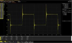
Tweeters - 2500hz for fun. is the crossover only cutting one side of the circuit, is that what am seeing?
hispeaker-2500hz.jpg


And the amplitude gets crazy from 7500hz and up

5000hz
hispeaker-5000hz.jpg


7500hz
hispeaker-7500hz.jpg


and than 12500; no change in volume setting...
hispeaker-12500hz.jpg


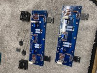
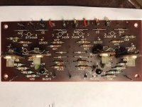
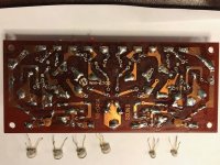
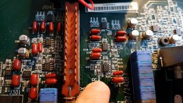
So with just the above, I don't think there is a timing issue. But certainly a crossover issue; and presumably given the age of these speakers and that there is apparently an electrolytic cap within, they're well overdue for a refresh and that will likely get the speakers back inline with each other.

I'd attribute me thinking phase issue at first because of how I didn't really notice much volume difference with up close listing comparatives. but suppose adding in room acoustics, slightly different amplitude, listened to at a normal distance could perhaps impacts sound like that.


Does that all seem reasonable? the difference in measurements between channels is likely due to the crossover. I did measure the drivers and crossover section for ohms and all seemed fine to me. variance of 0.1ohm on the 7"drivers; presume is non-issue. both side had that variance. and at speaker terminals the speakers are within 0.2 ohm iirc. only mean to compare the two speakers here; does not tell me at 35watts, 120hz (lol) what kind of difference there is between them.

what a fun thing, measuring like this. some surprising results. in particular what audessey does to the signal / wave lol a VERY interesting comparative there would be measured at signal & from microphone; see if audessey corrects and to what degree.

Open source ULN regulator based on LT3042

This is a compact ultra low noise regulator I have designed in KiCad during Covid.
The goal was to have a small and capable regulator that may be used in a wide range of applications. It must be able to power my RPi projects and not only. It is based on LT3042.
So nothing special apart the fact is small, compact, open source and able to push 3A in any load.
Zip file contain KiCad files and gerbers as well.

Enjoy !!!

Regards,
Tibi

Attachments

  • Zeno KiCad.zip
    Zeno KiCad.zip
    97.6 KB · Views: 220
  • image2.png
    image2.png
    60.8 KB · Views: 557
  • image3.png
    image3.png
    119.2 KB · Views: 588
  • image.png
    image.png
    82.2 KB · Views: 553

What wattage should I expect from SSE? (AKA, pairing SSE with Bozaks)

Hello all!
I'm building a tubelab SSE amp. You may have seen my seemingly countless other forum posts about this recently... I've had a lot of questions, because I'm a bit of a noob!
It took awhile to pick an output transformer, but I finally settled on the TTG-EL34SE, since I have EL34 tubes to use with this build.
I'm wondering, given those tubes and those transformers, is there a way to estimate what kind of wattage I should expect?

I ask because I think I've found a pair of speakers I'll be using with this amp. They're the Bozak B401 Rhapsody. Turns out I've had them in my basement this whole time, and I think they'd be perfect with a tube system. They're 8 ohms input (the transformers I chose have an 8 ohm tap, so that's good) and what documentation I can find on them seems to indicate they require 15 watts minimum.
So I'm curious if the SSE could be a decent match for those speakers.

I've read that the amp might be able to get close to that wattage in UL mode. The transformer does have a UL tap. Anything I should know about configuring the SSE for using UL mode?

Microphone issue

Hey folks,

I'm doing a show where I'm having major issues with a mic cutting out. It's the only show of my day that has the issue and I can't recreate it myself.

The mic audio keeps on cutting out for several minutes at a time but I'm still getting a signal as it's showing when I solo it. It's definitely not a mic or cable issue as suggested by online mic test. I have tried replacing both and the rest of the channels on the desk work.

Does anyone know what the issue could be?

Using 807s in a mullard 5-20 circuit

Im wanting to build a class AB amp in UL configuration with cathode bias for driving a pair of 807 tubes on each channel and thought the mullard 5-20 design would be a perfect fit.
Obviously there will need to be some modifications to the phase inverter to suit the load lines of the 807, something im not 100% familiar with.
What I do know is that an 807 needs far more grid current to drive the tubes compared to an EL34 which is much more sensitive.
One bonus though is the EF86 voltage amplifier will help somewhat, as its regarded as a fairly sensitive amplifier.


Im considering running the tubes at 400-450V since ive found thats quite a sweet spot for the 807 in my guitar amp.


IIRC, 4K impedance is what I need on the OT, since my guitar amp runs with 2K on the primary with a quad.


Anything else I should know?

LAN server/player

Hi,

Since my beloved DAC has a LAN input (end point) and I find this input way better from USB, I'm looking for an affordable (not beer money, but I'm not ready to pay 2000 eur for a Melco 🙂 LAN player/server, not sur of the name I must use fur such thing.

So ethernet IN/ethernet OUT with stream capabilities as I use TIDAL as source.

I'm not IT engineer so must be pretty plug&play

Thanks

Massive ringing with IPP320N20N3

Thought I had found the ultimate MosFet for class D
Have been experimenting IPP320N20N3 instead of my usual IRFB5620.

I really though one of my boards was fried as I en the first test got massive ringing.

I mounted another board up with IRFB5620. Only limited ringing (before mounting of snubbers).
Then changed to IPP320N20N3 ...... see pictures!!!

Boards based on IRS2092 with ZXGD3003E6 buffers and 4R7 gate resistors.
Pre + post filter fb.

Data sheet would suggest this is a real good MosFet, fast, lower Rds(on), higher current capability, low Ciss ... all in all better than IRFB5620 !!

Anyone having experience with these Fets?
What am I missing here?

Attachments

  • IPP320N20N3.JPG
    IPP320N20N3.JPG
    118.9 KB · Views: 464
  • IRFB5620.JPG
    IRFB5620.JPG
    105.1 KB · Views: 447

Tube Recties and a pair of Dht

Tubes for the Lampizator crowd

Hi all.

The psvane acme 274b i did use for a couple of hours,so it's more or less new.Asking 200 euros.

The 5U4G is a lampizator edition with approx 500 hours on it.Asking 200 euros

Mullard Gz34 is Nos,just tried it in my lampi so i can confirm it's working as it should.Asking 130 euros.

Kr242 Dht used for max 200 hours:500 euros

Have a great day all

Kindly/Ingemar

Attachments

  • 6.jpg
    6.jpg
    16.6 KB · Views: 169
  • EAD887CB-59DA-45A3-82A8-D66F10C3F7C9.jpeg.67fb40a09705f4af50b5f683a059afd6.jpg
    EAD887CB-59DA-45A3-82A8-D66F10C3F7C9.jpeg.67fb40a09705f4af50b5f683a059afd6.jpg
    514.3 KB · Views: 163
  • IMG-20210201-WA0005.jpg
    IMG-20210201-WA0005.jpg
    281.2 KB · Views: 167
  • 1..jpg
    1..jpg
    13.3 KB · Views: 169

Recurring Horrible noise coming from Desktop PC

Currently I have a new desktop connected to my DAC (Steinberg UR12) via USB (tried powering using USB powered and powered to wall), which is then connected to my amp which is a Yamaha AX-497 via RCA cable, which then connects to 4 passive KEF speakers.

Only weeks earlier this system was connected to my old computer (ASUS X555 Laptop), and I never ever had any sound issues or problems at all with playback of music.

After a lot of conversations with friends who are audio enthusiasts and looking at forums online it sounds to me like it’s a ground loop issue, but maybe I am on the wrong track there (based on what I have found recently).


Here is a sample of what kind of noise I am getting from my audio.

Recurring Sound Issue - Steinberg UR12 to Amplifier to Kef Speakers - YouTube


It’s a whining noise and it recurs every so often when playing music on either YouTube, or iTunes. This noise does not occur when no playback of sound is occurring. However, if I plug headphones into the audio jack on the onboard soundcard on my desktop, no sound issue is heard.


So after finding this out, I ordered ART Dual Transformer / Isolator (DTI – Link Below) and another shielded RCA cable.

DTI – Dual Transformer/Isolator – ART Pro Audio


The system then was Desktop>USB cable to Steinberg UR12 DAC> RCA cable from DAC to ART DTI> RCA cable from ART DTI to Yamaha amp> Amp via stereo cables to 4 speakers. The idea of the ART DTI was to be a form of Galvanic isolation so that the noises from the desktop weren’t coming through the signals of the RCA cable. But after installing the ART DTI I was getting still the same sounds produced.


This was very frustrating as the guy at the audio shop thought this would isolate the two appliances, my desktop and my DAC, from creating a grounding loop. It seemed to make sense to me, but then no change in sound quality which was disappointing.

Things to note:

-my laptop doesn’t have this noise problem and never has with the exact same set up. I wonder if the noise is there because there has been a change of power supply? Or my desktop has RGB lighting and my laptop does not (interference?)?

-the DAC has been tested by being powered both with USB and via power to the wall with no change in the noise

-the noise I am experiencing isn’t occurring when no music is playing

-Dual Transformer / Isolator didn’t prevent the noise from occuring


What does this mean? I am very stuck here. I have no idea what is causing this problem or where to go next. Maybe I could try another type of DAC? Do I take the desktop back to the shop and look inside the case to see it is all grounded properly (I’m thinking maybe the power supplies ground isn’t a good enough connection - I remember grounding an amp in a car once and I wasn't getting good sound until the earth was attached to bare metal not painted metal - could this be a similar issue?)? Is the reason why the onboard sound card works and the external DAC doesn’t because the USB ports aren’t grounded well but the onboard 3.5mm jack output is?

Any help would be greatly appreciated on this one as I have been driven absolutely mad trying to solve this problem.


Thank you in advance,

James

Balancing the secondaries

Hi I'm working on a 2 channel Marantz amp. I moved the bridge rectifiers and main caps off the board to a discrete power supply, followed by 18ga shielded copper wires back to their original location where extra 2200uF caps are in their place. I've also installed a DAC module.

The amp has two sets of secondaries, one powering the transistors and the other powering everything else.

1. The original configuration has the 0V lines tied together at the main caps by a small wire. Was this an afterthought, or was it intentionally a wire rather than a board trace? Should I leave it there, should I move it to the new power supply (closer to the transformer), or should I remove it now that I've added more capacitance?

Before:

before.png


After:

after.png


2. I'm worried that I'm drawing too much current from the positive swing of the second secondary. Is this sub-optimal for the op-amps? Will they have too much of a negative bias thereby affecting sound?

I'd love to power the DAC with the negative swing but I would need a negative buck regulator which is rare, and I would also have to isolate the casing of the DAC module because it will still be 12V south of the "grounded" amp casing, creating a short.

Am I being stupid trying to use the amp's transformer and I should just add another switching power supply? The off-the-shelf ones are more noisy than the mini buck regulator I think.

Thanks!

Recommendations for alternative/upgrade from Eminence Beta 15" drivers for OB

I am in the process of revamping my open baffle speakers with a new baffle, and I'm wondering if there is an obvious upgrade route for the woofers (one per side) from my Eminence betas. I'm not particularly disappointed with the betas, but I suspect there are options that are audibly better. Unfortunately, the Hawthorne Augies are no longer available, and Pure Audio Project no longer sells their woofers separately. What else is out there that works well in open baffle speakers?

Here is my (slightly weird setup):

Tannoy Monitor Gold 15" covering most of the audible spectrum.
Eminence Beta 15" handling the low bass
Biamped using first watt b5 crossover
ACA driving the Tannoys

For now the crossover point is pretty high - 80hz -to take the load of the ACA, but I'll experiment with different settings when I finish building my First Watt m2.

To some extent the speakers were made with available components, but they do sound good.

F5 V3 Boards (stuffed) w/ parts

I am selling off this F5v3 project I started but, because of a new job, I will not have time to finish. What you will receive:

- 2x F5v3 boards (completely stuffed w/out Jfets)
- 4x 4.7k ohm NTC thermistors
- 2x CL-60 thermistors
- 1x 3300pf safety capacitor
- 1x 4 screw terminal block
- 2x GBPC3502 35A diode bridges
- 2x blue leds
- 4x Heavy duty washers (for the mosfets)
- P3 trimmer set to mid-way before installing

Asking $115 SHIPPED to the CONUS only please. Will be shipping from Houston, TX.

Attachments

  • IMG_3529.jpg
    IMG_3529.jpg
    208.7 KB · Views: 247
  • IMG_3530.jpg
    IMG_3530.jpg
    189.9 KB · Views: 242
  • IMG_3531.jpg
    IMG_3531.jpg
    180.6 KB · Views: 232
  • IMG_3532.jpg
    IMG_3532.jpg
    187.6 KB · Views: 226

Armstrong 600 series balance potentiometer

[comment][/comment]Hello Forum!

This is my first post here - wooo!

I come to you with a problem. I have an Armstrong 625 receiver (I also have a 621) working 99% ok. The only problem is the balance. In the neutral point only left plays. As I go toward right left start fading, right nothing. When I am about 80% to the right, right starts playing loud (as it would play if it would be at that sport). I suspect since the unit was store in a damp area, the potentiometer is damaged (it also moves hard to the right than other potentiometers). How can I replace it? I look on the internet but I could not find any potentiometers for this specific units. I suspect is a common one. But I need to identify it.

Can you help me?

Ive attached a picture form internet, but it is similar to my unit (even tho this is 621, the part is the same)

yy9WjXq.jpg


Thank you!

Hk

I’m sick of gutter

Man! every website I go to there’s an advert for improving my gutters to keep the leaves out. it’s everywhere I can’t escape from them I don’t know why. I don’t remember ever clicking on one of these things to leave some kind of trail which encourages them to chase after me but everywhere I go every website somebody wants to sell me a solution for my gutters. it’s completely out of control. it’s on YouTube it’s on the news channels. is there a leaf epidemic?

Tannoy v12 drivers 3142 in folded horn design ?

Hello all

Im looking at building some folded horn style cabinets for a set of drivers that i have acquired, old tannoy v12 drivers which are 3142. Ive done alot of trawling the internet to see what I could come up with but I cannot find anything that will work exactly. I dont know about the complexities of speaker design so need some pointers on how to go about this. I understand the basics of the folded horn principle but need to figure of the dimensions that will work.

Any help greatly received!

thx
Grif

PSU consideration for SE amp

I've got 2 semi-related questions regarding PSU in SET amp.

1) CLCRC (tube rectified).
B+ 315V @ 100mA.
L = 10H, 150ohm.
2 combinations reach the same target voltage,
-5U4GB with R=270ohm
-5R4GYB with R=50ohm

The first option has more resistance in the PSU (420ohm vs 200ohm), but lower ripple (based on PSUD).
Also, alot more voltage is burned on the resistor vs. the rectifier.
Which is better and why?

2) CLCRC (SS rectified)
200uF-100uF-100uF or
100uF-100uF-200uF

Is there a difference?
PSUD gives about the same ripple result at the last cap, is there any other consideration?


Thanks!!

Help with very old Transistors

A coworker's father purchased this back in the 60's or early 70's I guess. He asked If I could look at it as it keeps blowing the fuse. What I found was a paper clip inside the unit. I first checked the final transistors and One was dead short and the two 0.5 ohm suzuki wire wound's where burnt on that channel.

I found replacements (NOS) NEC 2SD154 Transistors and replaced them with the resistors. Nothing else seemed shorted with a quick check around the driver board.

Turned unit on and no smoke! but 24 volt on the speaker outputs...Both channels!

Digging further, found one of the diodes leaking. I pulled the bias and driver transistors and did the normal ohm check.
Here is the question???
I get meg ohm readings from base to collector and base to emitter but no readings from collector to emitter. Almost like it's open. Is this normal for these very old transistors?
I also found one open capacitor. Fun Fun...
It's similar to a Sansui AU 555A stereo.

Attachments

  • IMG_1115.jpg
    IMG_1115.jpg
    137.8 KB · Views: 449
  • IMG_1120.jpg
    IMG_1120.jpg
    120.5 KB · Views: 442
  • IMG_1117.jpg
    IMG_1117.jpg
    124.3 KB · Views: 439
  • IMG_1119.jpg
    IMG_1119.jpg
    166 KB · Views: 434

Variations in tube heater current

Hi guys,

I was going to do some experiments with a high-voltage SRPP stage for my ESL direct drive voltage amp stage with 6HS5 tubes.

I got a quintet of Raytheon packaged and marked 6HS5's and yesterday I wanted to check out their heater current profiles. This is important as these will be fed with floating DC-DC converters with limited current surge capability. The nominal heater current is 1.5A @ 6.3V, but to my consternation, 4 out of five drew 2.4A @ 6.3V!

Interestingly, there are variants of the 6HS5 like the 6HZ5 with 2.4A @ 6.3V heater, and the 6HV5(A) with 1.8A @ 6.3V. They only differ in heater current, the rest of the data sheets are identical as far as I can see.

But the ones I have are clearly marked 6HS5. Do these things happen in tube country, that heater currents can vary so much, or maybe that marking is somewhat loose?

Jan

Phonic Max 1500

Hi, I have a Phonic Max 1500 power amplifier. One of the channels is distorted only under load.
Another problem is that the schematic I found online does not matches to the amp's PCB.
For example: in the schematic there are 2608 op amps on the pre amp section while in reality there are two 5532 and a half of 13700D per channel. Also the components values and numbers are mismatch with the schematic.
Does some one have the schematic for this version?
Any idea how to troubleshoot this distortion issue?
Here you can see pictures of the output signal with and without 8 Ohm load, also attached pictures of the PCB's and a link to the schematic:

Attachments

  • 180515129_214337813473121_3650730366023078409_n.jpg
    180515129_214337813473121_3650730366023078409_n.jpg
    126.4 KB · Views: 274
  • 180583697_3027659830893580_6463028618989349248_n.jpg
    180583697_3027659830893580_6463028618989349248_n.jpg
    127.2 KB · Views: 288
  • 180505583_286019816513921_2741074631314693966_n.jpg
    180505583_286019816513921_2741074631314693966_n.jpg
    184.9 KB · Views: 562
  • 180550442_536336247372958_2567983713627837983_n.jpg
    180550442_536336247372958_2567983713627837983_n.jpg
    158.9 KB · Views: 412

Compact Disc Motor and Turntable - Advices for Replace and Motor Service wanted

There are two kinds of disc motors: those that are suitable for disass'y (brushless in most cases) and those for "one way" use, not suitable for disass'y without destroy.
By today's cd/dvd mechanism in most cases the last mentioned are in use. Naturally the complete mechanism is renewed in case of a failure inside in disc motor. And if this mechanism no longer available (by older models very often to observe) an other solution than throwing away the complete compact disc player I wanted.

To make matters worse additional pressed turntable are to find in most cases instead such with set-screw for exactly hight adjust
I perform the remove of such pressed turntables and and re-press to a new motor device several times (mostly by Linn Karik), but this is a very unpleasant work. I want to know better solutions.

About post #16 #19 and #21 about
http://www.diyaudio.com/forums/digi...ailable-optical-pickups-sonys-kss-series.html
you will find first ideas
But because the thread there is a complete other topic, I start this thread here.

It would be very interesting to know, which brands offers several motors suitable for complete disass'y (removable sinter bearing and removable sliding touch in case of not brushless versions).
If there are brushless versions for 1:1 exchange (same sizes, same arranged screw holes and same shaft diameter than the common used Mabuchi's), it would be also interesting to know.

I have found this URL in this case:
?PHILIPS???????????CDM9????_jjjjjj1_????
interesting, but all motors not suited for 1:1 exchange

Additional various turntables (motor-pulleys) with set screw for exactly hight adjust are very helpful for motor service by cd mechanism. Therefore brand names for this I want to know. Because there are various clamper forms in use (arround 10 different versions I know) is always necessary to choice the each matched turntable.

Thank you for all advices.

Layout of Ethernet Isolators

Hello everybody,

Since I have noticed a very positive effect on the sound of several end devices through Ethernet isolators directly in front of the end devices when streaming music, I am currently working on their construction and building some myself.

Ethernet magnetics are used for isolation, which are also used for coupling with Ethernet end devices. These usually consist of a transformer with a common mode choke behind it. This reduces noise on the line, which is noticeable in the better sound.

Picture of the DeLock Isolator:
Delock-62619-Platine.jpg


Here is picture and a circuit diagram of a typical 100BaseT transformer:
pl22989502-48_pins_ethernet_lan_transformer_h2017nl_poe_gigabit_ethernet_transformer.jpg


download.axd


The center taps on the cable side are terminated with the Bob Smith termination: termination with 75Ohm resistor and 1000pF capacitor to ground.

The center taps on the PHY side of the transformer are integrated in the connection to the PHY.

As you can read here, the Bob Smith circuit is not without controversy: Why is Bob Smith termination for Ethernet recommended if it's wrong? - Electrical Engineering Stack Exchange

When using the Ethernet magnetics as an isolator, it is in the middle of the cable - so it has no PHY side.

Are there any suggestions as to whether the center taps should also be terminated with bob smith termination or whether not to terminat? Should one make the termination against earth?

Would really be grateful for any input.

Best regards,

Tom.

Updating Crimson Elektric CE608 and CE1008 modules

Hi, I have an active speaker system based on Crimson Elektrik power amp modules that I put together a number of years ago. They use CE1704 issue VII modules for the bass, and CE608 issue 5 for the midrange; the piezo tweeters are powered by OPA544 power op-amps. I am about to replace all of the electrolytic capacitors in all of the modules as they are probably all 40 years old! I bought the CE608s new over 40 years ago and they have been working perfectly daily since then and are entirely 'untouched'. The CE1704 modules were bought from AndrewT about 10 years ago.

Anyway, to the point. I remember reading on here that Brian Powell, who designed the amps, posted details of how to upgrade issue 5 modules to issue VII, but I have looked and the details are no longer downloadable. It also appears that Brian's latest post was about 2 years ago. I would like to carry out the upgrade while the speakers are 'down'. Does anyone have the details of this upgrade that they are willing to share?

Cheers, Keith

Rockford T1500-4 schematics / help

Hi guys,

Does someone has the schematics of the Rockford Fosgate T15004 amplifier?
The amplifier seems to have a slightly broken trace in the PCB which seems to be present in the filtering circuit. Only channel 1 seems to be affected by this problem.

The amplitude of the output sine wave on the speaker terminal is much lower then it should be. Pressing on the board (see attached photo) makes the output sine wave sometimes as it should be. Sometimes the music signal dissappears on the speaker terminal.

I cleaned all the switches and and resoldered the switches to make sure there is a good connection.

Attachments

  • PHOTO_20210429_152246.jpg
    PHOTO_20210429_152246.jpg
    1,017.3 KB · Views: 118
  • PHOTO_20210429_152301.jpg
    PHOTO_20210429_152301.jpg
    1 MB · Views: 105
  • PHOTO_20210429_152317.jpg
    PHOTO_20210429_152317.jpg
    999.5 KB · Views: 108
  • PHOTO_20210429_152330.jpg
    PHOTO_20210429_152330.jpg
    975.9 KB · Views: 103

Four lug capacitor replacement

Hi all,


I am using a NABU case from Nebraska Surplus to build another Pass B1 buffer. This will be my second with the NABU case, which comes with an 18v power supply.

Alas, the units date to the mid-1980s. The caps physically look good, but given their age and ease of replacement, it seems like a good idea to replace them.

The main filter cap is a Rubycon CE 69 W (22,000uf, 16v), which is listed as a snap-in capacitor.


s-l500.jpg


The confusing part is that the cap has four lugs. One is clearly a dummy, two are clearly active, and one is?


The cap has a diameter of 40mm and the live lugs are not centered, but toward one side.

(Picture is not mine, but the cap illustrated is the same series):
RUBYCON-6800uF-80V-Radial-Electrolytic-Capacitor-_1.jpg


The lug on the left-hand side (9:00 o'clock) is definitely a dummy used for support purposes.


My question is if I would I order a 3-lug replacement?

Thanks for any help you can give me!

miniDSP 4x10 Hd sounds really good!

Just wanted to give my recommendation for the miniDSP 4x10 Hd. It's a really nice product and a bargain for the price.

I've tried both GroundSound DCN28 and DEQX HDP-4. I haven't compared all of these together but have compared each one to my reference Lynx Two-B soundcard (going straight to amps). Speakers Geddes Abbey and Hypex nCore power amps. I have been running the miniDSP with unbalanced outputs so far by the way.

Sound quality using digital in, the miniDSP is better then GroundSound. Not doubt. When it comes to a comparison to the DEQX HDP-4, I'm not 100% sure. The DAC in the DEQX sounded too bright IMO and was sort of sticking out. I'm not hearing this with miniDSP. Compared to Lynx Two-B both the miniDSP and DEQX has a tiny veil over the sound. The Lynx Two-B sounds a bit more clear and transparent. Not sure which comes closest, but overall I think the miniDSP is the best. It was hard to distinguish it from Lynx Two-B. I believe there's a difference in transparancy which makes the music sound a bit more real with the Lynx, but the difference is really small. Very impressive for a product for this price.

The software is also very easy to use. There are a few things I'm missing, but they may come in future upgrades.
A strongly recommended product. Much better then the Behringer DCX2496. There's no noise with the miniDSP.

Go to 2021 DIY amplifier for higher power 4ohm?

A little over 13 years ago Diyaudio introduced me to the Aleph-X and after a year or so of effort I've happily rocked to these for over a decade with my old B&W 805 Nautilus.

I'm currently looking at a speaker upgrade, likely B&W 800 D3s and got to thinking about amplifier requirements. The reviews of the speaker have been rather critical of the 8ohm nominal rating that B&W applied to these, with a low impedance of 3ohm, and an impedance at around 4ohm for much of the 60-900Hz region these things will likely draw a bit more juice than a 100W Aleph-X is capable of.

So maybe it's time for me to build something new.

I've been out of the game for too long. Is there a go-to high end DIY amp that people can recommend which can put a couple of hundred watt into a 4ohm load? Also I know I'm coming from a Class-A Pass certified space heater, but I'd be open to consider Class-D modules as well.

Speaker driver sound signature

Hey
I have been messing my speakers and i feel something is missing.

Speakers is 3 way
tweeters are dayton rst28f or seas 27tbc/g
midabass is peerless HDS 6,5"
Bass is polish STX 12"

I feel the weakest link is tweeter, with RST28F sound is almost there but detail is not good and upper range energy is weak, maybe it is too soft, but it measures very well. Resolution is not the strongest side too.

seas 27tbc/g this tweeter is very smooth sound and resolution is ok, but sound is not right, wooden stiks sound very unnatural, rst28f is much much better.

I have good experience sb satory ring radiator tweeter (but it sounds little bit dark) and scan speak illuminator

so my question is
how diffrent is scan speak 9130 compared to rst28f or other scanspeak revelator illuminator series
Also i'm intrested little bit morel and wavecor tweeters, but i dont have any experience with those.

Does anybody knows is HDS glassfibre has more midrange clarity than nomex cones ?

Get Issues With Your Vintage Portable CD players?

I have researched most of vintage portable cd players made by Sony, Panasonic, Philips, Denon, Aiwa, Citizen, Toshiba and Kenwood.
I will replay any technical question about the following models:
Sony: D50 D50MKII D55T D100 D150 D250 D350 D303 D555 D99 D90 D3 D2 D2T D66 D34 D33 D121
Panasonic: SL-XP7 XP5 XP3 S505 S900 S700 S470 S490
Philips: CD10 AZ6808 AZ6819 AZ6826 AZ6804 AZ6805
Denon: DCP50 DCP100 DCP150
Aiwa: XP50 XP66 XP77 XP6 XP7
Citizen: CBM1000 CMD3000
Toshiba: XR-P20 P21 P22
Kenwood: DPC-80 92 R7 7 77 92

Welcome any technical question!

Identify an IC - M-Audio USB sound card

Hi everyone,
I'm new here, I found this place after looking for an integretad circuit in my sound card through the web... I hope I'm in the right section.

My M-Audio USB soundcard is not working anymore, after a few volt measure and a visual control I think that I found the problem et I'm thinking about fixing it.

Here it is (not my pictures), on the right top there is an IC referred as U22 with 8 pins, a very small one :

https://gearfoxblog.files.wordpress.com/2015/10/img_20150129_0048341.jpg


On this second picture it is referred as 57 2110 :

https://gearfoxblog.files.wordpress.com/2015/10/boardchips.jpg

But on mine I read 05 2110.

First of all, does anyone has an idea of what it is and where to buy it ?
Secondly, do you think I can fix it by myself ? I only have a regular soldering iron.

Sorry for my English and thanks a lot for your time and answers.

Pearl 2 Phono PSU Parts For sale

For sale are a majority of parts needed to build a simple/small Power supply for the Pearl 2 phono. What you will receive:

- Hammond Chassis (200MM wide x 175mm deep) black or silver face
- Antek AS-0524 (24V secondaries & 50VA)
- 2x GBPC3502 35A Bridge diodes
- 1x KBPC3510 Bridge diode for Ground loop breaker
- 1x Round Power switch
- 1x IEC inlet
- 2x 3 prong Power plugs for umbilical cord
- 1x piece of 21 inches of Canare 4s8 cable for umbilical
- 4x rubber feet

Asking $100 shipped for everything CONUS. Will be shipping from Houston, TX.

Attachments

  • IMG_3533.jpg
    IMG_3533.jpg
    147.5 KB · Views: 152
  • IMG_3534.jpg
    IMG_3534.jpg
    112.6 KB · Views: 158
  • IMG_3535.jpg
    IMG_3535.jpg
    115 KB · Views: 147
  • IMG_3536.jpg
    IMG_3536.jpg
    177.1 KB · Views: 156

FS: Two Tubelab SSE PCB

Hello. I have two unused Tubelab SSE PCB's. I purchased these boards myself and they have remained untouched and stored in there tote since they arrived at my home. I'm not going to use them. I would like to sell both of them to one buyer.


2 SSE pcb's for $70.00 shipped free in the USA.


Paypal. Thank you.

Attachments

  • IMG_1549.jpg
    IMG_1549.jpg
    204 KB · Views: 638
  • IMG_1550.jpg
    IMG_1550.jpg
    220.6 KB · Views: 626
  • IMG_1551.jpg
    IMG_1551.jpg
    334.5 KB · Views: 617

Amp Camp Kit Parts For sale (Almost all parts you Need)

I built some upgraded Amp Camp amps and had some parts left over for a couple more amps. Because I just received a job promotion, I will have little time to finish building these last two amps. What I have for sale is:

4x 100% working Amp camp 1.6 boards (toshiba Fets and IRFP 140 mosfets)

4x Cap Multiplier PSU boards (untested but stuffed)

4x KBU8 Bridge diodes for the PSU boards

3x IRFP9140 for the PSU boards (1 more needed)

2 RCA Jacks (1 left and 1 right - one more set needed)

1x Switch On-On (one more needed)

2x XLR female panel mount iputs

1x Set of Speaker posts (one more set needed)

2x Power switches

12x Large washers for mosfets

2x IEC inlets

The main parts you need to finish the amps are the two chassis', remaining parts listed above, and the two Antek AS-2220 torroidals.

I am located in Houston, TX and selling all the parts together for $200 plus shipping.

Attachments

  • IMG_3490.jpg
    IMG_3490.jpg
    185.6 KB · Views: 288
  • IMG_3491.jpg
    IMG_3491.jpg
    173.1 KB · Views: 294
  • IMG_3492.jpg
    IMG_3492.jpg
    182.3 KB · Views: 289
  • IMG_3493.jpg
    IMG_3493.jpg
    187.4 KB · Views: 275
  • IMG_3494.jpg
    IMG_3494.jpg
    185.1 KB · Views: 280

EV P1202

hi guys.the amp when turned on doing on relays a sound like arc for one two seconds and after start normal. its like to try to start dificult.i replace all three relays the ptc the q560 trans few suspect diodes and the near ceramic cap..check everything and it looks fine.the strange is for a month is stopped to do this and start quiet and normal and before three days come back the same problem.i have resolder the most joints on the board.whats wrong? any idea somebody?

Where to buy quality solid state components

Hi guys,

I am new to transistor stuff. I have been building tube amps for a good while and know where to buy tube stuff.

I live in Miami Florida. I buy transistors from Mouser and DigiKey electronics. Are there better places to by things from known MFGs like Texas Interments or Fairchild or other well known brands?

I bought some JFETs off Amazon which had no data sheets I could find. I had the same issues with tube stuff in the beginning until I found reliable venders.

I am looking mostly for discrete components and op-amps and a few ICs.

Thanks,

Billy

Arduino Mega Pro DIY Power Supply

Hi everybody,

I'm working on a headphone amplifier project and I want to use an Arduino Mega Pro to control a MUSES72320 volume control board. The arduino needs 7-9V and a maximum of 200 mA. Since I want to integrate the power supply into the headphone amplifier case, I don't want to use a switching power supply to avoid high frequency disturbances.

Do you have a suggestion or schematic for this application?

I'm thinking about three solutions right now:
1. A transformator in combination with MUR860 diodes.
2. A transformator in combination with LM2574N-ADJ
3. Something like this for 7-9V: Security Check

Will option 2 or 3 introduce high frequency noise just like a conventional laptop switching power supply?

Thanks
seyl3r
Projects by fanatics, for fanatics
Get answers and advice for everyone wanting to learn the art of audio.
Join the Community
507,756
Members
7,886,873
Messages

Filter

Forum Statistics

Threads
406,164
Messages
7,886,873
Members
507,756
Latest member
CalmRiver