1. Constant loop gain for no THD both @ LF and HF,
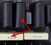
2. No coupling capacitors at all, MC-like sound with MM cartridge thanks to
3. aperiodic non-resonant HF correcti on with lowest input capacitance.
Thanks to that, the unwanted resonance of the input circuit is shift ed far into the ultrasound region and
does not manifest itself in the audio range, and the input resistor R1 can be increased to 150 kOhm, thus
forming a "passive cooling", which reduces the input noise current in SQRT (150 kOhm / 47 kOhm) = 1.78
ti mes compared to typical Rin = 47 kOhm.
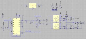
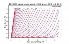
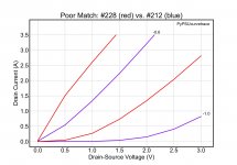
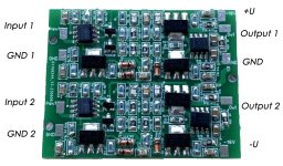
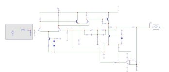
4. At the front end uses a matched pair of Dual, ultra-low noise, low-gate-current audio N-channel JFET -
the latest JFE2140 from Texas Instrument. It's allow to achieve a record IEC-A weighted signal-to-noise
rati o of 85 dBA relati ve to a standard 5 mV@1 kHz input level with an att ached 0.5 H+ MM head
equivalent. 1 kOhm
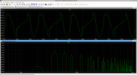
5. and THD less, then 0.00006% with fantasti c overload capacity (64 mV@1 kHz < 0.0007%).
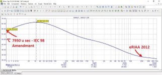
6. The frequency response exactly corresponds to the Enhanced RIAA not with three, as usual, but with
fi ve -ti me constants, in additi on to 75 + 318 + 3180 µs, a Neumann pole compensator and a rumble -
reducing 7950 µs - IEC 98 Amendment are also implemented.
7. Double differential stages scheme : high PSRR , but stabilized bipolar +-(15-18)V power supply with low
ripple is required
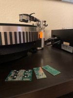
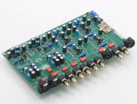
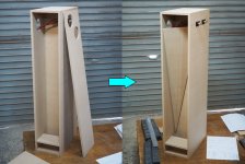
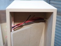
The preamp board must be installed next to the tonearm to ensure the stated performance
$200
Discussion here
MM
Frequency range: 1 Hz - 45 kHz
Ku at 1 kHz: 49 dB
Rated output voltage: 1.4V
Signal to noise rati o: >85 dBA
THD: <0.00006%
MC
Frequency range: 1 Hz - 45 kHz
Ku at 1 kHz: 68 dB
Rated output voltage: 1.4V
Signal to noise rati o: >73.9 dBA
THD: <0.0004%
Welcome to test it in Dresden, Germany
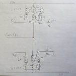
In order for the parameters of phono stages to be compared with each other, they must strictly comply
with the regulati ons established in parti cular by IEC 61938. In this case, the input of the device should not
be short-circuited, but should be loaded onto the equivalent - for MM this is a circuit consisti ng of
inductance 500 mH, in series with a 1 kOhm resistor and a capacitance of 125 pF connected in parallel to
them. For MC - 10 Ohms. The nominal input signal level for the MM is 5 mV, for the MС - 0.3 mV. Noise
parameters must be A-weighted.