Can this I/V circuit be adapted for differential DAC output?

Hi

Can anybody help with this please?

I plan to build a PCM1798 DAC using the attached circuit for I/V conversion if its input can be adapted for connection to the PCM1798's differential outputs. I have been using the circuit as shown with a TA1541A, without the FET output buffer shown in the diagram, driving the following amplifier via a stepped attenuator and like its sound very much, therefore if it can be adapted for differential input I would like to try it with the PCM1798.

Can this be done and if so what would the new circuit look like please? I hope this isn't a stupid question and thank you in advance to any help offered.

Tim

Attachments

  • IV&Buffer.GIF
    IV&Buffer.GIF
    8.8 KB · Views: 601

FS: Electra-Print Output Transformers EU

I have a very nice pair of Electra-Print output transformers for sale.

They were bought for a 300B PSE amplifier that was never finalized. The transformers have the following specs:

Primary: 1.5K
Primary current: 150 mA
Single secondary: 8 ohm
Power level maximum: 30 Watt
Weight: 7 kg. each.

These transformers are big and heavy.

The current retail price at Electra-Print for this type of transformer is 405 USD each - total 810 USD. On top of that I paid 120 USD to have them shipped to Europe + VAT.

As can be seen from the photos the transformers are in 100% like new condition.

I am selling these transformers for 460 Euro + shipping. Price reduced to 400 Euro.

Attachments

  • Trans1.jpg
    Trans1.jpg
    326.9 KB · Views: 833
  • Trans2.jpg
    Trans2.jpg
    479.4 KB · Views: 826
  • Trans3.jpg
    Trans3.jpg
    649.9 KB · Views: 814

IXYS 10M45S CCS for 6E5P tube driver

IXYS 10M45S CCS for 6E5P tube driver

Hi, i have an 6E5P KT88 triode amp with resistor load for 6E5P.

I will change and will use a 10M45S CCS.

Somebody know about resistors values ​​of the resistors to have 25-30mA current.

I put the present diagram with load resistance 6E5P and the future diagram with CCS 10M45S for 6E5P.

Attachments

  • 107617701_3141417112609908_6541520022556528088_n.jpg
    107617701_3141417112609908_6541520022556528088_n.jpg
    179.3 KB · Views: 1,461
  • 107083156_637945550142884_2340318169294291153_n.jpg
    107083156_637945550142884_2340318169294291153_n.jpg
    42.7 KB · Views: 1,166

some proac info. look at this everyone

Proac are a little mean on what they divulge, so I thought I would share a little of my hard earned knowledge, and give a kind of database of proac info for fans and curios
.
for some great proac klones check this out.

http://audioclone.free.fr/scanspeak.html

Older proacs are divided into 3 ranges,

1/the tablette

2/studio

3/ response

tablette 3, 50, 2000 inc. signatures use seas woofers and seas or scanspeak tweeters...2010 on signatures.

further info added: tablette ref. 8 still using seas bass unit, but treble is now changed to vifa tweeter, these appear to be oem units.

xover is still the std proac seas type, 2nd order on bass, with rlc across woofer, between the inductor and cap.
cabinets do not feel as substantial, terminals are cheaper too, but it is true to say after listening to the 3s, 50s, and ref. 8s, that in every incarnation, they have subsequently sounded more open, better bass and clearer mid, so it would appear they get better with every new model, and its not hype.

studio 1, 100, 200 use scanspeak 8543 paper woofers and seas tweeters
studio 125 are like the tablette 2000, and use seas woofer
studio 150 use seas p14 woofers, and scanspeak 2008 tweeter.

studio 200 and 250 use the 8543, like the studio 1, in the 200 they are in a dapplito and the 250 there are 2 of them, not sure if a 2 or 2 and a half way.

response 1s use seas t14 woofer, scanspeak 2010 tweeter
1sc uses a different woofer.
reponse 2.5, well you know!!
reponse 3 and 3.5 both scanspeak polypropylene woofers, scanspeak 9000 series tweeters

apparently, the r3 cones were made by rogers, and were changed for the 3.5. They are plastic coned.

response 3.8 uses 2x 8535 woofers, 9300 tweeter
response 5 2x8535, atc mid, 2010 tweeter
response 4 atc 9 inch short voice coil woofers, atc mid, scanspeak tweeter.

response 4 crossover is 2nd order bass, 2nd order on the mid(lower and upper) and 2 order on the tweeter, a departure from the normal proac xover.

response d150 and later proacs are now using volt woofers, and some using scanspeak tweeters.

You see a lot of the drive units are similar, the favourites are seas woofers, usually the plastic polyproylene cone: t14, p14 or p17....in the seas woofers, the letter is the cone material, t for TPX a kind of plastic, p for polypropylene, L for aluminium, and the number is the diameter in cm,

and the tweeters usually scanspeak 2008 or 2010 tweeters, and there is really little distinction between the ranges, the tablette are the small ones, some studios are uprated tablettes:
the studio 150 is like the tablette 50, studio 125 is like the tablette 2000.

Studio 200 are the same as the studio 1 or 100 just another drive unit and bigger cabinet.

response d15 is like the tablette 2000 signature: same drive units, bigger cabinet.

response 2.5 is like the studio 125 only different drivers which is the floorstander version of the tablette 2000

Proac seem to favour a d'appolito configuration which is used on studio 150, 200, response 3, 3.5, and the latest responses.

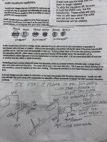
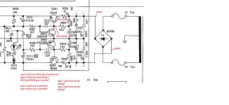
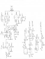
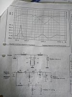
crossovers: the standard proac crossover is 2nd order in the bass, 3 order in the tweeter, with one attenuation resistor as the first component in the tweeter. No L-pads here.

They are in phase, but the components are the opposite way around, ie in the negative path rather than the positive.

With the 2.5, the bass is 3rd order,a change for proac with a 47 ohm resistor across the first inductor.

The 3.8 crossover is 2nd order on the bass unit, at 300 hz, and the rest I think is identical to the 2.5 ie 3rd order midbass, 3rd order tweeter.

With the scanspeak woofers, no resonant filter is used, but with seas, a series RLC circuit in that order R, then iron core L, then C is used, ACROSS the woofer. The bass signal first passes through the series inductor, THEN comes the RLC, then the parallel capacitor...check this out for a typical proac crossover:

http://audioclone.free.fr/responseONEsc.html

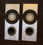
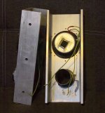
The cabinets are lined with bitumen and acoustic foam, terminals are michell rhodium plate.

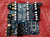
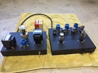
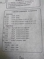
with the crosovers, the FINESt components refers to air coiled inductors, solen capacitors, and ceramic resistors. Pretty standard, and some standard multilstrand cable, a la qed or bandridge.

latest response d100 uses Volt 2500 type woofers, atc mids.


series RLC on the seas woofers comes after the bass inductor but before the parallel capacitor.

Values are typically: 4.7 ohms for the tweeter resistor, 5uf cap, choke, 6.8uf cap

woofer: choke, 10 ohm resistor, choke, 20-40uf cap in parallel with woofer, 5uf cap parallel with woofer.


that's about it, good luck....data by name, data by nature.

all this has been written in the belief proac are mean with their specs they divulge, and it ought to be in the public domain.
Its a shameful practise when you see the specs. some makers give, especially in the pro audio domain.

IMO there is no need for it, as proac use custom drive units largely, so no one can reproduce the designs at home.

Also, I consider Mr proac a minor genius, he manages to produce excellent speakers, and interestingly they all sound similar, despite having differing drive units, I supsect its a lot in the xover design, which are frighteningly similar on all the speakers. Minor tweaks are obviously the way he designs.

Speaker cabinets are made by the castle factory, and I have heard the xover boards are by bk electronics, who used to make the amplifiers for rel subwoofers.

Wharfedale SW150 Active Subwoofer help

Morning All,

The units red LED lights up, but no sound at all.
I have tested all components, except for the relays, the zener diodes, and the ICs' (I do have a list of measurements but don't understand them). If a component did not test correctly in circuit, I have removed, tested, and refitted, and so far all test O.K..
The unit was not fitted with the Green Auto-LED (there is no mount / hole), which I have subsequently fitted (the PCB has the required header). This had no effect and does not light.
I get +15v & -15v at Con105 shown centre of the schematic which connects both PCBs'.
I get +44.8v on the collectors of Q107/8 & -44.8 at Q110/111 output transistors (?).
I have a reasonable DMM, but no 'scope.

Cheers & hope someone can help,

Tony

Attachments

What makes a good pre-amp value for a guitar amplifer?

What makes a good pre-amp valve for a guitar amplifer?

What I'm interested in here is approaching the question from the perspective of a designer.

I know that selecting the operating point to have some clean headroom and also allow for significant harmonic distortion via cascading gain stages is typical for a guitar preamp, and, they are predominately ECC83 based.

I'm interested in playing/designing with different triodes and pentodes, but when I read the data sheet they all look very similar.

In the attachment I am comparing ECC83 with EF80 and EF86.

  • The anode voltages are all similar ~250V
  • The grid voltage ranges are similar
  • ECC83 and EF86 have lower plate current
  • The EF86 has much lower (x6 smaller) mutual conductance than the EF80
  • The EF80 has much high screen and voltage and currents and much lower anode impedance than the EF86

I see that the "non-audio" tube here (the EF80) has higher current on the anode and much larger current swing for a given change in grid voltage (the mutual conductance).

Why do the "audio" tubes prefer a lower mutual conductance? Or maybe I'm generalising too much.

What are the characteristics of a "good" pre-amp valve for a guitar amp and why?

Attachments

  • Screenshot 2021-05-18 at 22.53.19.png
    Screenshot 2021-05-18 at 22.53.19.png
    381.1 KB · Views: 207

oscillation problem

I'm having a problem with my power amp. It is a design from Elektor mag called IGBT power amp. Its schemetic can be found below:

http://web.tiscali.it/audiofanatic3/Tipo/Stato_solido/pic_finaliSS/140W_IGBT_GT20D101_201.jpg

The problem is that there is a burst of oscillation on the peaks (both positive and negative) of the output. This only happens when the output level exceeds 30W (I measured with a 5 ohm resistance). The oscillation is observed on the powers rails and also slightly on the output itself.

Does anybody have a clue as to resolve this problem?

Usually I only play at 1-2 W level, at which the oscillation is not present. Would oscillation at these higher levels affect sound quality at listening levels?

regards Abo

R.S. Bailey 20+20 Watt Power Amplifier

Good Day Everyone

Has anyone here build the A.R Bailey amplifier from Daan Jacobs from the early 1970's.

i have started with the rebuild of this amp that i got from my father but i only have the diag. but there is no information on the Trifiliar Transformer on the diag. i am looking at updating the components on the am and this is my 1st stumbling block.

This am uses TIP2955 output transistor's.
Sorry i am a noob with electronics i just know enough to not kill my self.
All help will be appreciated.

Thanks.

FS: DiyStore & Cviller PCBs

FS: Extra Printed Circuit Boards from my Stash (see pics)

1 Pair (2) - Cviller F5 Ver. 2.0 $15.pair

2 Pair (2) - Cviller F5C (Cascode Version) Ver. 2.2 $20.pair

1 Pair (2) - DiyAudio Store ALEPH J Ver. 2.0 $20.pair

1 board (2channels) - DiyAudio Store UNIVERSAL POWER SUPPLY Ver. 3.0 $20.(2 channels)

Shipping for the above boards dependent upon quantity ordered.
1 pair $4.00 Lower US 48 states Only
1 pair $10.50 Canada
1 pair $14.25 all other International

SOLD ALL OF Full Set Pass Burning Amp Boards w/extra pair SE Output

I have a full set of Pass burning Amp Boards with extra pair of Single Ended Output Boards . All current version 2.0. (Total Store Cost $107.0)
Sell entire set, only ! $70. + actual ship cost ($37. below cost ) or I may consider dividing along a singular build complete set.
Includes:
P-BAS-S4V20 - Burning Amplifier Single-ended Bias and Output Set for the BA-1 & BA-3 (4 boards) (2)BA-SO v2.0 & (2)BA-SB v2.0

P-BAC-S4V20 - Burning Amplifier Complementary Bias and Output Set for the BA-2 & BA-3 (4 boards) (2)BA-CO v2.0 & (2)BA-CB v2.0

P-BASO-2V20 - Extra pair of Single-Ended Output boards (2 boards) v2.0 (no longer sold separately)

(2) P-BAGS-1V20 - Burning Amplifier Gain Stage for BA-1 & BA-2

(1) P-BAGSN-1v20 - Burning Amplifier Gain Stage for BA-3

Attachments

  • IMAG3938.jpg
    IMAG3938.jpg
    595 KB · Views: 708
  • IMAG3940.jpg
    IMAG3940.jpg
    434.5 KB · Views: 696
  • IMAG3959.jpg
    IMAG3959.jpg
    470.5 KB · Views: 691
  • IMAG3966.jpg
    IMAG3966.jpg
    856.3 KB · Views: 684
  • IMAG3942.jpg
    IMAG3942.jpg
    587.2 KB · Views: 668
  • IMAG3944.jpg
    IMAG3944.jpg
    617.8 KB · Views: 183
  • IMAG3950.jpg
    IMAG3950.jpg
    603.9 KB · Views: 159
  • IMAG3951.jpg
    IMAG3951.jpg
    319 KB · Views: 153
  • IMAG3954.jpg
    IMAG3954.jpg
    493.1 KB · Views: 153

Duntech Crown Prince Dynaudio woofer replacement

I just got a pair of Duntech Crown Prince speakers and they're flat out amazing. However, when pushed, I hear the woofers splatting/bottoming out unlike any other speakers I own. I'm definitely NOT over pushing them.

They were recently professionally refoamed with Dynaudio foam but I think they messed up the voice coils or something.

Any remedies or thoughts?

I really need a whole woofer recone kit.

Duntech has been very slow to respond and I'm not sure they can even help.

FS: 2 pairs of Mark Audio CHP-70 speaker units (total = 4)

Selling 2 pairs of Mark Audio CHP-70 speaker units (total = 4)

Very nice units. New in box with receipt. Cost 92 Euros. Now £135 after Brexit!

Selling for £50 all four. Courier to mainland UK at cost, or collect Kensington W14.

Attachments

  • Markaudio1a.jpg
    Markaudio1a.jpg
    974.3 KB · Views: 216
  • markaudio2a.jpg
    markaudio2a.jpg
    1,014 KB · Views: 195
  • Markaudio5d.jpg
    Markaudio5d.jpg
    975.4 KB · Views: 187

Audax Aerogel 5.25" midrange new $40 shipped

GONE Audax Aerogel 5.25" midrange new- just pay postage

This is a 5.25" Audax HM130Z12 8 ohm unit, brand new in box, which is a replacement midrange for one box VR5s and HSEs and perhaps others.
I've not owned the VR5s for a bit, so this is just gathering dust.
https://www.audiocircle.com/image.php?id=219516
https://www.audiocircle.com/image.php?id=219517
I have the datasheet for it as well.
These listed for $67 when available and were bargains. I'll ship this to you for FREE, just pay usps shipping of $14, cont. US only.

Thanks for having a look.

questions about items in a circuit

im not sure if i should have put this here or elsewhere,but as im learning i dont realy have anyone to advise if im doing things right so attached is a diagram with a hypathetical voltage from the rectifier.


i just need to know if i am on the right track or not, and if not how i should be looking at it


ive put question marks against what i need to know


many thanks

Attachments

  • question 1.jpg
    question 1.jpg
    236.2 KB · Views: 262

buzzing in peavey tko 115 help please

hello i have an early 90's peavey tko 115 1993.
i think the buzz is about some where between 100hz an 140hz (twice the power frequency im guessing.

*it is not in the power amp because if i plug line into " pwr in" the buzz stops when the pre is by passed.

*the sound is constant and is not effected by adjusting any of the controls. or by plugging a lead in or out.

* there is no ground lift switch on this model

If any one has any ideas what it could be and what to try that would be great, here is a schematic link

PEAVEY TKO115 SCH Service Manual free download, schematics, eeprom, repair info for electronics

thanks

Attachments

  • 2016-11-16 (2).png
    2016-11-16 (2).png
    221.1 KB · Views: 375

Circuit of new to me 6B4G PP amp, Thoughts?

Hi Everyone,

I recently picked up this 6B4G push pull amplifier. I normally just stick to single ended amps but, I thought this would be fun to play with. My thoughts were that the extra power would give me the ability to use less efficient speakers and I love the sound of 2A3/6B4G's. The things I've noticed with it so far is that one of the output 6B4G pairs are more challenging to dial in the bias (I'm thinking that they're poorly matched or perhaps one of the tubes is on its way out?) the other anomaly I've noticed is that the overall volume will dip slightly, as if the volume was just turned down, and then in a few minutes come back up again (both channels). I'm going to check my other gear to make sure it isn't a problem with what's feeding it.

I'm currently debating about splitting the amp into two monoblocks. I was wondering what people think of the current circuit. If I should keep it or modify it.

Attachments

  • 6B4G PP amplifier001.jpg
    6B4G PP amplifier001.jpg
    257.4 KB · Views: 306

clicks and pops with RPi4 and Audiolab M-Dac via USB

Hi,
I am trying to set-up a system around my Audiolab M-Dac connected via USB to a RPi4.
Unfortunately I am getting regular clicks and drop outs every few seconds.

I have tried PiCorePlayer (pCP) and Volumio with the same result. In pCP there are a lot of tweaks around the USB interface but non of them worked. I am using WLAN but as the output via the RPi-headphone-out is OK I don't think this is the issue.

The M-Dac works well when it is connected to a Squeezebox touch with the advanced digital output plug-in installed.

The buffer level in the M-Dac is fluctuating a lot and also the sampling rate display is often not correct although I don't do any data processing (at least not on purpose).
The M-Dac is running on the Lakewest firmware.

Any ideas? Has anyone this combination up and running fine?

Joe

Audiolab M-DAC main board, hiss on left channel

Thought I would sell this as it has a very nice DAC chip, ES9018S and some polymer capacitors et.c. I already have enough junk 🙂

Discarded due to hiss on left channel.
Heard in head phones. With my insensitive speakers it wasn't very audible.

Asking for 75€ or any offer!

Board has the older SW, V0.90 I think?
But it is easy to upgrade, I can help if needed.

Shipping anywhere, but outside EU might cost around 35€, EU around 20€

I am fine with any reasonable arrangements and suggestions 🙂

Attachments

  • 2019-03-12 13.33.16.jpg
    2019-03-12 13.33.16.jpg
    1 MB · Views: 840

XYS IXTP08N50D2 and IXTP08N100D2 LTspice model

Has anyone been able to model the XYS IXTP08N50D2 or XYS IXTP08N100D2

I have found Psice models on similar but does anyone have one built??
Just not sure how to build a model in Ltspice, Ive found how to change a pspice to ltspice but there are no psice models for those two and just need a hand. Thank you all!!


Parameter

IXTP08N50D2
VDSS, Max, (V) 500 ID(on), Min, (A) 0.80 RDS(on), Max, (Ω) 4.600 VGS(off), Max, (V) -4.5 Ciss, Typ, (pF) 312 Crss, Typ, (pF) 11 Qg, Typ, (nC) 12.7 PD, (W) 60 RthJC, Max, (ºC/W) 2.08 Package Style TO-220

Parameter

IXTP08N100D2
VDSS, Max, (V) 1000 ID(on), Min, (A) 0.8 RDS(on), Max, (Ω) 21.00 VGS(off), Max, (V) -4.0 Ciss, Typ, (pF) 325 Crss, Typ, (pF) 6.5 Qg, Typ, (nC) 14.6 PD, (W) 60 RthJC, Max, (ºC/W) 2.08 Package Style TO-220
http://www.mouser.com/ProductDetail/Ixys/IXTP08N50D2/?qs=6UKyFUzHTlmmDo5v2SbtuQ==

SVI3206 operation

I have a Technics SA-GX710 with 2 SVI3206 (main and center amp) and 1 SVI3202 (rear amp). The outputs of both SVI3206 go trought relays. In normal operation, after power on the relays remain inactive for 4 seconds. I connected a 100W speaker and activated the main relay manually: the sound have distortion with medium and up volume but I don't know if it's a speaker problem. I can't find what is wrong with this equipment (I don't have schematic). I think both ICs work fine, but I don't have the relay signal (-14V) in pin 18 to activate the relay. I compared both the SVI3206 pins voltages and found differences that I don't understand because I don't know the function of pin 7 (Latch C). In various circuits I saw the voltage of this pin is similar to voltage of pin 10 (VCC). In my case, I have -7V instead of -14V.
Anyway, in the other SVI3206 I don't have this difference but have the same problem (ausence of relay signal).
How the relay output signal is generated? Someone have any data of this IC? Thanks in advance and sorry for my english.
Best regards,
Javier
Argentina

Tymphany 830656 MLTL design review

I'm still cooped up during covid, and needed a project so I pulled a pair of 5-1/2" Tymphany SDS drivers out of the closet and decided to build a small 2-way out of them. If they work decently well, they will wind up flanking the TV in the family room where my wife spends a lot of time sewing. Limited bass and output are fine for the application. No sub will be used. A pair of Peerless DQ25SC16-04 tweeters arrived today, chosen for their decent reputation, reasonable cost and small size that should allow fairly close c-c spacing. I'll first set them up with the MiniDSP, and take measurements to see if I can design a decent passive crossover.

Not wanting to build stands, I turned to MJK's MLTL worksheet to see if I could come up with a reasonable floor-standing box using the T/S parameters as measured with the Smith and Larsen WT2.

I have attached the output from the worksheet, as well as the parameters used and a snapshot of the predicted frequency response. Short version, 36" tall x 6.5" wide x 6" deep, 2" dia x 4.5" port. Does this look like a reasonable design? The driver Qt is a bit high, so modeling a conventional BR in WinISD tends to give responses with a rise around 100 Hz, or a peaking response at the port tuning. This looks quite flat, and predicts better excursion control at the bottom end (is that due to additional resistance to flow in the narrow enclosure?), but will that pan out in a decent real-room bottom end?

Any comments or criticism would be welcome, thanks!

Bill

Attachments

ACA Heat relief

Hello Everyone
I’m joining for the first time and have no clue how forums work (be gentle)
I’m building 2 ACA 1.8 amps and I’m curious if anyone has put a computer fan inside one to keep them from burning down my house. Or is that just crazy thinking
I’ve seen some dinky 24v fans that would work but don’t known about the downsides. Any input would be greatly appreciated.

Retiring/Moving Sale- available for pick up in Southern California

Prefer local sale, you can listen/test before buying:

1. Built by Min Yang at: Home one 6SN7/6SL7 tube preamp with separate power supply. Includes (2) 76 tubes, (4) 6SL7 tubes, (4) 6SN7 tubes, (1) Westinghouse rectifier Tube. This preamp has 6 inputs total, including one MC phono input. $1200

2. Unassembled Spud Amp kit. Includes (5) 6CL6 tubes and (5) 6197 tubes. $350

3. AR XA turntable with Jelco tonearm. $450

4. Hafler DH-200 amplifier and Quintessence Preamp. Prefer to sell both for $500

Pick up in Pasadena, CA

Attachments

  • IMG_0001.jpg
    IMG_0001.jpg
    805.1 KB · Views: 561
  • IMG_0002.jpg
    IMG_0002.jpg
    822.7 KB · Views: 553
  • IMG_0004.jpg
    IMG_0004.jpg
    859.5 KB · Views: 532
  • IMG_0007.jpg
    IMG_0007.jpg
    708.6 KB · Views: 527
  • IMG_0008.jpg
    IMG_0008.jpg
    698.2 KB · Views: 528
  • IMG_0009.jpg
    IMG_0009.jpg
    743.9 KB · Views: 168
  • IMG_0010.jpg
    IMG_0010.jpg
    503.5 KB · Views: 232
  • IMG_0011.jpg
    IMG_0011.jpg
    578.7 KB · Views: 217

Electrolytic Capacitor Fault Question

Hello Everyone
I know enough to not be dangerous and have built point-to-point tube amp kits, but do not have a detailed knowledge of electronic components.

I have an Auralic Vega that, out of nowhere, started crazy distorting when anything but garbage came out of the balanced outs. The single ended outs would distort at high levels and were putting out a much reduced level.

I put it on an oscilloscope and it was clear most of the negative half of the signal was cut off. The Balanced showed junk at lower levels then then a cut off waveform at high levels. The single ended looked OK at lower levels but then were cut off at higher levels. For those familiar with the piece, the transition was around 80 out of 100 on the volume scale (supposedly 0.5dB per step) but does not seem stable.

The balanced outputs are supposedly class A so the lack of the negative portion of the signal on either phase of the balanced output made me think the negative power supply feeding some portion of the output circuits had failed. The single ended output is supposedly derived from the difference between the fancy class A balanced outputs, by the way. Both channels act the same.

So I opened up the unit and started carefully measuring the voltage at a few points I recognized in the power supply. Out of curiosity I measured the voltage at the aluminum seal at the top of the electrolytic caps. All were negligible (0.25 to 0.33 VDC, 0.2 to 0.3VAC) except one that was at -19.43 VDC and 0 VAC. My understanding is the seals should just float and are not tied to a terminal of the cap.

Has this cap gone to Component Heaven? Could it be the problem or a symptom of something else? Nothing I can see looks scorched or burnt or otherwise like it overheated, but most of what I think are regulators have heat sinks on them so I cannot see them.

Thoughts anyone?

FS: Thurlby-Thandar 30v, 2A Variable Bench Power Supply x 3

Thurlby-Thandar 30v, 2A Variable Bench Power Supply x 3

Not working at present but could be repaired. Asking £25 for all three.

These are top quality bench supplies, usually over £50 used.

Collection from Kensington Olympia W14, London UK

Could maybe be sent - contact me for details. Total weight for three is 14kg

Attachments

  • bench supplies1.jpg
    bench supplies1.jpg
    947.7 KB · Views: 150

Amber 3501A Dist. & Audio Analyzer Needs Refurb and Cal.

Amber 3501A Audio Analyzer Needs Refurb and Cal any info would be helpful.

Hello
Does anybody know of somebody who could Refurb and cal. a Amber 3501A Audio Analyzer. Also if somebody has refurb there own any insights would be appreciated. If I can't find a tech I will do it myself.
Please PM me with any info or post in the thread.
Thanks in Advance.
bOTL

Need help with Hornresp (strange output)

Hello guys, and especially hello David! 🙂

In the last few days, i was simulating a couple enclosures for my subwoofer (mostly with WinISD).
I allways liked the idea of a 6th order serial tuned bandpass, wich was unable to simulate until now, when i finally found Hornresp!!!


But i am pretty confused, at what Hornresp outputs me, compared to WinISD
I got strange peaks in the result, so i simulated a simple closed box, to see, if atleast this looks familiar, wich was NOT the case.
When simulating a closed box, im get just 1 big peak as result, like the following picture shows:

955281d1622144732-hornresp-closed-5l-hornresp-png


The same driver, in the same 5l closed box in WinISD looks like this:
955282d1622144732-hornresp-closed-5l-winisd-png


I mean... ok... im sure the flat line at 100Hz and above is not true in WinISD, but this peak in Hornresp also looks unreal to me.
But it is not just the way, how it looks, also the point, where it starts dropping is totally different.
-> WinISD starts dropping at ~100Hz and below, the Hornresp simulation has its peak at 60Hz and drops below that

Just to let you have all the informations, here a screenshot of my input window:

955284d1622145196-hornresp-input-png


I realised, when i choose "-> Tools -> Maximum SPL", it looks a bit more, like what WinISD outputs, BUT still verry different AND, i can not select this menu, when i simulate the bandpass. The menu is just not there, when i select a bandpass simulation, instead of a closed box.


Edit:

i am sorry, i didnt want to double-post. I allready posted my question into another thread, but i didnt know, it takes a while, until it shows up... so i thought my post didnt submit correctly, and posted it again here.

First attempt at reflow soldering

Hi folks


I had a go at using my kitchen oven to reflow solder some DAC chips onto adapter boards and it was only a partial success.


I put on a liberal amount of solder paste and have ended up with the chips securely soldered onto the boards, but a lot of left over solder paste. I tried soaking them in a bath of Isopropyl and scrubbing them with a soft cloth, which took most of the paste off, but there is still loads left in the nooks and crannies.


I take it I need to get rid of all of the leftover paste as it will be somewhat conductive. Question is, how to do it, try different solvents or put them back in the oven?


Three came out aligned nicely, the CS4398 is wonky and will need to be redone.


Next attempt, I take it I need to use as little solder paste as possible? Any tips for applying the paste and how much to use?

Attachments

  • DSC00416.jpg
    DSC00416.jpg
    203.6 KB · Views: 294
  • DSC00417.jpg
    DSC00417.jpg
    229 KB · Views: 282
  • DSC00419.jpg
    DSC00419.jpg
    620.5 KB · Views: 263
  • DSC00419b.jpg
    DSC00419b.jpg
    627.8 KB · Views: 268

New filter Focal Kit C800

Hi!
I have old loudspeakers, Focal Kit C800, with Focals filter. According to the documentation, the crossover slopes 18dB/oct. Would like to update the crossovers to newer and "better" components.

Regarding the filter design. Is this an standard design? Would appreciate some info about the used design.

All the components are, at least what I think, quite large value components.
For instance:
The low pass filter for the base has quite large caps, two 75uF in parallel. New ones, non-electrolyte, this large can be difficult to find and expensive.

Is it possible to scale down the filter values so that smaller value components are used? How will this effect the sound.
Maybe update the filter design - start from scratch? Preferable filter design?

Are there any recommended filter designs/layout regarding sound quality (and price)?

Thanx in advance

Roy

Attachments

  • DSC_2969.JPG
    DSC_2969.JPG
    616.8 KB · Views: 280
  • DSC_2970.JPG
    DSC_2970.JPG
    524.1 KB · Views: 273

Arcam Alpha 9p blowing fuse

Hi all,

I have a 9 / 9p bi-amp set up with some Monitor Audio floorstanders. All has been well until suddenly last night the 9p went dead. I opened it up and the internal 230v mains fuse in the lower right corner had blown. There was a spare on the board, so I replaced it and it blew immediately again.

Can somebody give me some tips on where to go from here? I'm not an electronics guru, but I know how to solder and use a multimeter.

Furthermore, the "T1A6L" fuse as marked on the PCB, doesn't show up in Google. Does anybody know the spec for this fuse (it's a different socket for 230v and 115v - I need for 230v)? I think I'll have to buy a few replacements.

Thanks in advance.

Pairing speakers to First Watt amps when space is limited

When dreaming of winning the VFET lottery I wake to the cruel reality that I can’t fit dorm fridge-sized speakers into my life. My listening is nearfield monitors on my desktop or very limited placements options in my living room. My odd shaped living room is full of obstructions like built-ins, kids, dogs and Lego houses that mean only a small footprint speaker close to the wall fits. An open baffle plank placed two feet from the front wall would be meme-worthy but short lived.


I’ve considered a number of solutions. All compromise bass for smaller enclosures, acceptable if I can get low enough to add a subwoofer in the future. The top three:

1) The right full range. The Seas F22RCZ in a tall, shallow ported box could approach 3 cubic feet, but would have to sit against the wall. Madisound says the F22RCZ can go sealed in 0.65 cubic feet. That might even fit on my desktop.

2) According to the spec sheet, big coaxials can work in small boxes. I don’t see a lot of enthusiasm for it. The 3 cubic foot tall, shallow vented enclosure discussed for the F22RCZ could fit a 12” or even 15” coaxial. Sealed, I could go as small as a 12” coaxial in one cubic foot ala a Zu cube clone.

3) Not worrying about sensitivity. 10 watts ought to be plenty for speakers 3 feet from my face, right? Still… professional reviews of First Watt amps and my own experience tells me not all speakers work. I had KEF R100s that sounded glorious driven by 30 watts, but only at volumes that made desktop listening unpleasant. What measurements other than sensitivity make for a good match? Paper cones only? Or what specific drivers? A simple full range monitor with the Scanspeak 10F/8414G10 could be fun, but they’re just so insensitive.


Due to budget and limited free time, I’d need to avoid $1000 drivers, CNC cut horns and esoterica. Otherwise I want to hear how others would, or have, dealt with pairing First Watt-style amps to speakers with 5- to 60-liter volumes. Please critique the options I’ve listed, offer new ones or share a favorite pairing of a low power Pass amp to small and/or low SPL speaker. I realize this thread might fit better in the loudspeakers forum, but I’m particularly interested in speakers for a Sony VFET amp, should I be lucky enough to win one.

In Wall Speakers

Hi all,
I am currently doing some DIY (of the home improvement type). I will be building a partition dry wall which lends itself to designing in an in-wall speaker setup. The room will have a footprint of 3m by 4m and a height of 2.4m. It will be our 'snug' (a smug middle class term for a compact cosy sitting room). The speakers would be in the 4m wall so facing the 3m distance.
The main constraint will be the depth which I estimate will be about 84mm internal. The internal width could be up to 330mm and the height has less restriction so could be anything up to 2.4m (but I'm guessing up to 1m would suffice). I was wondering if a MLTL or something similar would work and I was thinking of the MA CHN110 (good price at the moment at KJF). It would be a stereo pair for mainly TV use and occasional music listening.

FS: Monacor open baffle midrange unit.

Open baffle frames with Monacor SPH130AL speakers. These are massive frames in 1cm thick aluminium.

Size 38 x 15 x 7.5cm. Opening for tweeter or port = 7.5cm diameter

I used these previously as full range units in a box constructed around the frame. Sounded very clean!

Ideal for mid and tweeter units in a 3 way system. Holes in the sides for attaching mounting brackets.

Can be collected from Kensington, London W14, UK. Or could send for price of courier. Asking £20 for the pair, negotiable.

Attachments

  • monacor2.jpg
    monacor2.jpg
    943.8 KB · Views: 167
  • monacor2a.jpg
    monacor2a.jpg
    870.1 KB · Views: 179

Need help: rebuilding crossovers for Pinnacle PN8+ speakers

I have a pair of Pinnacle PN8+ speakers. I have had them a really long time. Basically I want to rebuild/ refresh the stock crossovers because those capacitors and other parts are probably due for a replacement due to old age. They sound fine to my untrained ears, but I am not an audiophile, so I don't have a clue what I'm doing.

Another question is what other speakers are these equivalent to? I'm trying to figure out if selling these would be a better idea, I don't know if they're even worth $150 and if that's even worth the hassle or if I should just toss these. I have been reading about DIY speakers and the Swan/ HiVi 3.1A DIY speakers seem like the best cheap speakers to buy. These are the best speakers I've ever owned, they sound very good to me but I have nothing really to compare it to other than briefly listening to Magnepan at an audio store, but those speakers are way too expensive.

So if these are keepers than my questions are, can you help me identify what types of capacitors these are and tell me what I should replace them with? The treble already sounds like it's on the verge of being too high ("bright"?) so I don't need to make them brighter.

I'm not really looking to change the sound that much so should I replace it with exactly with what originally was there including the electrolytic capacitor or is replacing every capacitor with Dayton polypropylene capacitors okay in order to make them last longer without changing the sound too much?

I just need to make it clear, I have no clue what I'm doing so if you could provide links or exact names to new parts I'd appreciate it. I would just buy the original KSC capacitors if I could find out where to buy it and which ones to get.

Are the blue capacitors polyester/ mylar capacitors? I heard polyester lasts for 40-50 years but it's already been 15-20 years so should I replace them?

What is that mysterious yellow large 7.3J (7.3 uf?) round capacitor? is it a Tantalum capacitor? I'm attaching photos and a link to pictures of someone else who rebuilt these crossovers. he never listed what the original capacitors were so I cannot figure out what to replace it with that's why I'm here. The only parts store I'm sort of familiar with is Parts-Express

here's the pictures I took of my crossover:
pinnacle pn8+ crossover — ImgBB

here's the link to better pictures of the parts from someone else: Pinnacle PN 8+ Crossover rebuild — Polk Audio Forum

I know 1 blue capacitor is impossible to read I will figure out what it is later, I just need advice on what to do

Any thoughts on Meyer Sound

Hello all, I might need to post this in a pro audio forum as well. I have had pretty good luck using pro audio drivers for my speaker building projects. Right now I have a jbl 2226 with a 2446 on a yuichi horn. Been pretty pleased with the results.

I have a chance to pick up 2 Meyer Sound USW-1 "subwoofers" for pretty cheap. I have had experience with Meyer Sound and generally think they use quality parts.

The drivers are labeled as MS-15 and I have no idea if they are a rebrand of another driver (Radian maybe) or an actual Meyer Sound produce driver. Since there is little information on these I'm not sure if I would be gaining anything over what the jbl 2226 can already do. (Not looking to replace the 2226 but supplement it)

Just wondering if anyone has any information on these drivers, or at least a similar driver they can be compared to.

Bass Reflex Minimum Port Diameter Troubles

Hey guys, sorry if this post is in the wrong section.

So I'm building a bass reflex 2 way book shelf monitor and trying to figure out the minimum port diameter by using the equation provided in The Loudspeaker Cookbook. But for some reason, same with some of the online calculators, I'm getting strange results. I'm thinking its either the values I've input or I'm just being a silly sausage, I was never great at maths. The woofer I'm using is here:

Dayton Audio - RS150-8 6" Reference Woofer 8 Ohm

I know I could probably just pick a minimum diameter of around 3" but as this is for a university project I'd like to show some workings out.

A little bit about the values I have.
- Driver : Dayton Audio RS150-8 6" Reference Woofer 8 Ohm
- QTS : 0.34 FS : 47.8HZ VAS : 16.6 litres
- Chosen QB3 alignment
- Fb (tuning frequency) = H 1.1702 X FS 47.8 = 53.3926
- F3 = (f3 / fs) x fs = 1.3258 x FS 47.8hz = 63.37324
- VD = 34.03cm3


So the equations I'm trying to do are here:

Minimum port diameter - Album on Imgur

Equation 1 results:
Imgur: The magic of the Internet
172.2215769

Equation 2 results:
Imgur: The magic of the Internet
167.7433871

I'm assuming both results are supposed to be in inches? I've converted it from mm to inches just in case but nope, not a clue. 167 is a very high result.

Apologies in advance, I have checked other similar posts before but simply cannot get my head round it. Any help is appreciated massively.

Rel Qbass replacement driver

Hi
All

This forum is Amazing
I have a REL QBass subwoofer that is close to me that I would like to change the driver
I have been reading online and the ones people are replacing them with are the peerless or visaton


I have contacted BK and was told the visaton seems good. Seems like this is the original driver but I was hoping maybe to find something better
I done some research and found

Soundlab L042P, 12 Inch 200W 8 Ohm

I was told that the surround / edge is paper and is not good for a subwoofer
If someone can advise on this please

They are used in some subwoofers that some have mentioned online
The specs seem relatively same to the visaton and peerless
I was wondering if anyone has any experience with these drivers and if these would be a good replacement


Thanks all in advance

PPI 600.2 missing parts

Hi, does anyone have a close-up picture of a PPI 600.2 board that shows part numbers? I recently bought a blown one for cheap. When I got home and opened it up, I discovered that most of the output transistors have been removed. I’m not even sure that the ones left on the board are correct. The power supply is working fine with +40 and -40 on the rails. None of the op amps have power which makes me suspect that the missing Q18 might be a regulator. I’ve searched all over the internet for a picture that shows part numbers and location with no success. The few pictures I have found are too fuzzy to see the part numbers. Thanks in advance for any help given.

Attachments

  • 3BA9F58B-C490-4918-B1C0-69F045B5DD47.jpg
    3BA9F58B-C490-4918-B1C0-69F045B5DD47.jpg
    1.1 MB · Views: 70
  • A23A62B3-F1F5-4563-818F-AA31666DBDB0.jpeg
    A23A62B3-F1F5-4563-818F-AA31666DBDB0.jpeg
    335.5 KB · Views: 73
  • EE5D7A65-D785-4663-BE77-2BA708A5BCD3.jpeg
    EE5D7A65-D785-4663-BE77-2BA708A5BCD3.jpeg
    137.8 KB · Views: 72
  • 23699D8E-AC9D-4EFC-92EB-D08B0D417A9D.jpeg
    23699D8E-AC9D-4EFC-92EB-D08B0D417A9D.jpeg
    217.7 KB · Views: 71
  • 0BD565AE-BFC8-4416-8CFC-69771FB37EF6.jpeg
    0BD565AE-BFC8-4416-8CFC-69771FB37EF6.jpeg
    224.8 KB · Views: 81

AV Amplifier Output Specifications?

I've always wondered how the output specifications for these multi-channel amplifiers are devised. Typically, they'll specify 100w per channel (200w) in stereo mode and the same 100w per channel in cinema mode (500w).

No way on God's green earth can these units output 500w. What do they do? Do they use 5 x 100w chips with a 200w power supply? Or do they just lie?

The Intellectual People Podcast - Acry-Tech (DuraTex)

In 1985 Miki's father Dan, started Acry-Tech Coatings. While it started as a paint company, Dan quickly developed new industry leading products. Please have a listen to Miki to learn about Acry-Tech and learn about the new formula of DuraTex that makes it stand out from their competitors. From car audio, home audio/theater or Pro Audio, DuraTex Coating has you covered. 😉

Duratex Speaker Cabinet Coating | Acry-Tech Coatings | Miki Cappello - YouTube

Attachments

  • Acry-Tech Thumbnail.jpg
    Acry-Tech Thumbnail.jpg
    715.1 KB · Views: 85

Sugden preamp wal ac farnell

Are there any Sugden fans who might be able to shed some light on this unit?


Beautiful wiring, soldering and the feeling throughout of an utterly hand assembled unit but would appreciate some more insight and background.


I think WAL stands for Wellington Acoustic Laboratories, more than that I don’t know.


Would be grateful if anyone can comment on its likely sound quality.


To work as a phono preamp would it require an outboard RIAA?


What would be its best role in a system? Could it work as just a sitting box?


I haven’t yet fired connected it up, are there any readings I could check with a DMM?

Attachments

  • IMG_6939 copy.jpg
    IMG_6939 copy.jpg
    162.1 KB · Views: 359
  • IMG_6954 copy.jpg
    IMG_6954 copy.jpg
    641 KB · Views: 352
  • IMG_6947 copy.jpg
    IMG_6947 copy.jpg
    685.2 KB · Views: 338
  • IMG_6950 copy.jpg
    IMG_6950 copy.jpg
    730.4 KB · Views: 335

Reverse mid polarity in 3 way

Hi,

To the best of my ability I am only able to get a non problematic frequency response if I switch the polarity of either my woofer or my mid. The flattest response seems to be with the mid switched.

Are there any negative effects to switching the polarity on a midrange such negative effects on imaging etc?

The frequency response that I'm getting is:
vZyWj22.jpg

with blue being just the mid reversed, red being just midbass reversed and green being all in phase.

The crossover being used is:
aPIg0oz.png


The drivers being used are:
Tweeter - Dynaudio t330d
Mid - Dynaudio m560d
MidBass- AudioTechnology C-quenze 21i52

It's been a while since I've worked on speakers and any advice would be of great help.

Attachments

  • rew.jpg
    rew.jpg
    56.5 KB · Views: 410
  • xsim.PNG
    xsim.PNG
    129.6 KB · Views: 388

FS: Manufacture of amplifier housings according to your sketches.

If your project requires unique steel enclosures, I can offer my services.

Our production capabilities:
- laser cutting.
- metal bending.
- contact welding.
- painting
- laser engraving

Some samples of the work performed by us:

LB-Pro-1.jpg


An externally hosted image should be here but it was not working when we last tested it.


An externally hosted image should be here but it was not working when we last tested it.


An externally hosted image should be here but it was not working when we last tested it.


It is possible to make one case or a small batch.

The cost is agreed individually. We need a sketch from you, or a drawing and requirements for the case.

For correspondence, you can use private messages or mail zampotech.udav#gmail.com (you need to replace the # sign with the sign @)

dipole H-frame subwoofer using wall to form rear tunnel

I have mulled this idea over in my head for a long time, and I thought I would bounce it off of forum members to get feedback and suggestions.

I like to use large H-frames as dipole subwoofers for my OB/dipole speakers. But as the size of the 'frame gets larger and larger, they start to take up a lot of space and project out into the room. For example, I currently have a 1m deep H-frame having a cross section of about 0.6x0.6m. It's like a good size table. This has its first tunnel resonance around 150Hz or so, and I would like to build a version that is double the size/depth since this would still be usable below 85Hz or so. This is getting too long to be practical in the room. With an H-frame, the rear opening should be kept away from the front wall by at least 0.5m, so the other end would be sticking 2.5m out into the room. It's getting a bit too bulky.

Perhaps there is a way to reduce the bulk by about half. The idea is to "squash" the H-frame up against the wall so that the driver (midpoint of the 'frame) is located next to/at the wall and what was the rear tunnel is now a planar panel that is parallel to the wall but away from it by e.g. 15cm (6"). In this "large at/on wall H-frame" concept, the panel would be on the order of 2mx2m. The driver would be located at the center of this panel at the floor, and then a "front tunnel" would extend out in to the room and be about 0.75m long. Both the front tunnel and the rear panel will have different resonances because their geometries are different: the rear panel is open at the sides (similar to a tube open at both ends) while the front tunnel is like a tube closed at one end. There would still be an H-frame/velocity source character to it, with the rear acoustic output distributed around the periphery of the panel where the slot open to the room, and the front tunnel pointing at the listener. This would constitute a large, mono located between the left and right speakers. There would be one large driver used, e.g. 18" or larger.

By building the rear tunnel of this H-frame against the wall, the sub takes up less floor space yet should still operate as a dipole, e.g. velocity source. I don't have the ability to model such a structure, however, absent a model of the acoustic output I could just build a temporary version, measure the responses at the front and rear openings, and then model the in-room response by combining those, just like what is done for a standard H-frame. Of course I could also measure the in-room response at various locations as well.

This would go in my basement man cave listening space, and the "wall" in question is made of concrete cinder block.

Thoughts? Comments? Ideas?

Technics su-3500 fault search

Hi,
Thanks for letting me join your forum.

I have a basic knowledge of electronics.
I took it upon myself to repair this amp of a friend and learn a thing or 2 about amps on the way.
I left another forum because i got bullied for not knowing right a way what they were asking me.
I downloaded a service manual and can find the components if referred by partnumber. I know how to solder components.
(Love the smell too😁)

About the amp. Must be about 45 years old, it looks very well designed.
The power light is on. No sound, no humm of the trafo, no hiss in the speakers.
While i was looking around the relay clicked, which is there to protect the speakers, i read. So there is some current where it shouldn't be i presume. I read that faulty capacitors is a thing in vintage audio. I can't However see any bulging capacitors.
I'd like to know where to start looking for faulty components.
Hope some of you audio freaks like to share your knowledge.
Greetings, Henri

Linn Kaber crossover

Hi to everyone on here.
Looking for some help with my Linn Kaber crossover. I'm looking to upgrade the crossover by replacing the components and changing the pcb for point to point wiring.Is their a website that i could go to for the wiring diagram or could someone upload a picture of the diagram.Have drawn my own diagram from the pcb layout but not sure if i have got it right.Any help or advise would be gratefully accepted.

Thanks Steve.

Experiment - Clean wireless power for RasPi4/Digi One Signature

Is wireless power the answer to reducing noise in audiophile equipment?

I'm no expert in this field but these are my work in progress notes on providing a clean power source for the 'clean' power side of a Raspberry Pi4 and Digi One Signature HAT addon board.

Notes in the second section on this page

So far the results look promising, providing my use of a cheap scope is showing the results correctly! 🙂

Attachments

  • 20210522_100233.jpg
    20210522_100233.jpg
    928.7 KB · Views: 173
  • 20210522_103644.jpg
    20210522_103644.jpg
    778 KB · Views: 166

Balanced Class A Nelson Pass Preamp Remote Controlled

Hello to all of you!


I am quite new to the DIY business, have just built two ACAs and for now using them with a Teac DAC/Pre in Balanced Mono Mode. They are amazing! Now I would like the volume to be remote controllable and min 3 balanced inputs. So I know this is possible but as I don't yet have a lot of knowledge can anyone recommend a DIY project that meets my needs and has a build guide available?


Thanks in advance!

Rotel RB-850 channel imbalance

Hi all,

I have acquired a nice old Rotel RB-850 power amp.

Upon testing it I have noticed that the right channel is a lot quieter than the left.

There is no hiss or hum from the speakers, and everything sounds "fine", apart from the imbalance.

I have measured the DC offset at the speaker terminals after letting the amp settle for 10 minutes and each channel measures around 15mV.

Before I open it up and poke around inside, is there anything in particular I should look at? Is this a symptom of bad caps?

Thanks!

Setting up two parafeed amps for a special test rig

I am aiming to prepare a somewhat special pair of parafeed (PF) amps for the purpose of extending the range of output transformer (OPT) testing that has been discussed in another thread (Measurements on output transformers for the Williamson amp).

Patrick (Turner Audio) passed away early this month and I had been in sporadic communication with him for years, and most recently emailed him about a test amplifier setup he had made decades ago to test the performance of output transformers. So with a sad heart I will continue on with making a somewhat similar test amplifier that hopefully can apply an acceptably low distortion sinewave to an OPT, but with sufficiently high signal voltage to emulate up to about 15W in to a 10kohm PP OPT in a class A amplifier, and use a modern soundcard and software tool to characterise the frequency response and distortion of such an OPT. I'm piggy-backing on what Patrick seems to have prepared, which was a pair of PF amps using 6CM5 in triode-mode, and with sufficient feedback to achieve a stable test bandwidth from about 20Hz to upward of 1Mhz, and at low distortion (eg. circa 0.1%).
Parafeed%20test%20rig.PNG

As shown in the diagram above, the OPT DUT is driven by the pair of PF amps in a balanced configuration with the B+ (CT) primary winding node of the OPT grounded, such that each PF amp is loaded by just half the PP primary winding. In addition each amp has a resistor inserted between the PF coupling cap and the OPT primary anode tap so as to be equivalent to an output stage driving tube Ra (for the Williamson the test originally used 1.25k to be equivalent to the KT66 anode output resistance). The remainder of the test jig is already set up and has been used for OPT testing at low signal voltage (as per the thread link above).

I'm not aiming for each amp to achieve a 1Mhz top end bandwidth for a number of reasons, but as this is a test setup I do need each amp to aim for as low a phase shift as practical down at the 20Hz end, and likely going up through 100kHz, as well as negligible amplitude change. As part of a test rig using modern software, any phase shift of the test rig (that will include the PF amps, but not the OPT DUT) can be automatically 'calibrated out' by a loopback test, leaving just the phase response of the OPT being tested in the measurement.

The output power target is to get close to 15W in to a 10kPP OPT that has a matched secondary resistive loading. Given each PF amp is driving only half the primary, that implies a 2k5 load on each amp. But each PF amp is also driving the OPT through an additional series resistance of circa 1.25k, to make a total PF amp loading of 3.75k. 15W into a 2.5k load would indicate a signal swing of 275Vpk, but that increases to 375Vpk at the PF amp output due to the added series 1.25k.

The 6CM5 was and is both common and cheap here in OZ, and many have used it for audio applications including Patrick who ran it in triode mode at up to 375V Vak idle, and appears to have used it in his custom test amp. I have a large batch of them so initially for this application I will use them rather than the likes of 6L6GC etc that I have fewer of, but I can foresee that the 6CM5 is likely not going to achieve 15W where I want it, so this test jig may have to graduate over to 6L6GC for Rev 2 (if I get that far). The 6CM5 in triode mode has an Ra of circa 750 ohm, and I can easily use 2 in parallel.

To keep phase shift as low as practical at a 20Hz low frequency end each PF amp output is likely to need circa 100uF of coupling cap. That is easy to achieve with e-caps, although I have sufficient metallized poly caps with at least 500Vdc rating to integrate in with the e-caps if needed.

Each main PF choke needs to be at least 30H to allow operation down to 20Hz, and preferably around 50-60H. Although that choke can be a series connection of whatever chokes are available, each choke needs to have a suitably low DCR/Henry ratio along with a high enough Vac and DC current capability. I can presently get to 30H, but need to seek out some more boat anchors.

This is just a test amp so will be nothing pretty and will use a large derelict amp chassis and I have a range of PT's to choose from. An aspect of this test rig is that the two PF amps will draw opposite phase signal currents from a common B+ supply, so the effective B+ load is going to be fairly constant over the range of test signal levels applied to a test OPT. Also I can arrange heater power and sockets for parallel 6CM5 to try and reduce effective Ra and hence move the main PF R-L corner frequency down as far as practical to reduce phase shift at 20Hz.

This will be my first foray in to PF amps so I have been trying to do sufficient background reading to confirm that using a PF amp in this test setup is worthwhile starting, and so far I can't rationalise an alternative way to achieve the OPT testing I am targeting. So I will continue on with preparations and get a draft schematic prepared and start to appreciate what performance can be achieved with what I've got to hand.

Ciao, Tim

MAOP11 Enclosures

Hi All!

I got a set of Markaudio Tozzi One CHN50s a few months age for desktop use. Both my partner and I love the sound but both agree that they don't have enough bass extension and could be smoother so I've been given the go ahead to get get some MAOP11s (go all out she said 😀 ). However, there is a caveat. We don't have space for towers and for all intents and purposes, these would be treated as (largish) desktop or bookshelf speakers. I have access to a cnc router and 3d printer and am pretty handy with them, but I would like to get some input about the design itself given the requirements.

tldr;
What boxes should I make?

Thanks,
Nathan

MY Technics SU-8080 distorts in "Direct" mode only

Hi to everyone,

few days ago I've realized that my beloved SU-8080 Technics starts distorting quite soon, ONLY when the Main Amp Input selector is set to "Direct".....

Using the option "Via Tone", the amp reaches its full power without any problem, passing through the internal preamp section or directly feeding the Main In input.

This sounds very strange to me, as in both cases exactly the same power amp is obviously used... Just for info, the problem happens on both channels, but the distortion (easily audible as a cracking sound raising the volume) appears first on the left channel.

I've had a look at the schematics and I have seen only one difference: the "Mute" function (-14dB) is achieved by two different ways, depending on the position of Main Amp Input selector.

In "Via Tone" position, the muting is obtained through a normal couple of resistors (R233 and R235 for the left channel), while in "Direct" position a more complex solution is used, involving R357-R359-R361-R363-R365 and C323-C325-C327. As this net is directly connected to the infamous TR301 (2SA798a, a twin PNP) I'm wondering if the malfunction could be related to it, somehow. But it has to be said that in Via Tone position it works perfectly...

All the electrolytic caps have been recently replaced, so I would exclude any fault in this sense

Any idea about?

Thanks a lot in advance to everyone for your usual kind attention.

Have a better 2021!

Crown DC 300a

Hi All,
I have a series 2 DC 300a that has very distorted and low level output on both channels. There is practically no DC offset in either output, <.02v.
B+ and B- come in at 65vdc, measurements taken at the ua739 op amp are
+ 9.68v and - 10.17 at pins 14 and 7 respectively.
These voltages seem close enough however, where 1.35v should be present at op amp outputs A and B pins 1 and 13, only .63v are present when there should be 1.35v.
Am I at least looking in the right place?

Bluetooth receiver module with possibility to change name

Hi!

I'm restoring an old tube radio to have in the kitchen, and want to take the opportunity to install a bluetooth receiver in it to make it a lot more useable.

Getting a module to hide inside the cabinet isn't difficult; however, I would like to be able to name it myself, so that it will pop up with a more suitable name than "Zugong XPRO 1000 BT" or similar.

Is there any good off-the-shelf solution for this?

Newbie question: Design techniques for using power toroid as OPT

What is the method a beginner can use to properly spec and wire power toroid(s) for any given PP output stage impedance?

I have an LCR meter, is it as simple as loading the secondary to 4, 6, 8, 300 ohms, (whatever impedance my speaker is), and measuring what primary impedance I wind up with for a variety of stock power toroid's? Building up a list of power step down voltages (USA) that will work for various plate load cases 8K, 10K, 3.4K, 1.6K, 5K, etc?

I have 5V, 6V, 7V, 12V, etc. Antek sample toroid's in my stash now.

Schematics of projects you've done using power toroid's as OPT would help too.

Just trying to learn a repeatable method to ballpark-fit stock power toroid's for OPT usage, experimentally or using the limited specs from the mfg.

The little brother: Infineon MA12040 modifications

Hi,

I bought the MA12040 version sold in an enclosure and connector in addition to bluetooth. This one comes from ebay and the seller Douk.

I have already discussed this here on the MA12070 .

Infineon MA12070 Class D

The link on ebay:

Mini Bluetooth 5.0 Digital Amplifier Stereo Receiver 2.0 Channel Car Speaker Amp | eBay


My first message on Infineon MA12070 thread:

I was interested in the MA12070 PCB, but wanted to try before the MA12040 which is already in a box and with a Qualcomm QCC3003 bluetooth chip (not the best but handy in my workshop). So I bought from Douk and the delivery was quick. The amplifier is very quiet and no pop when opening.

Mini Bluetooth 5.0 Digital Amplifier Stereo Receiver 2.0 Channel Car Speaker Amp | eBay

From the power on I liked the sound. I prefer it to my stock 3eaudio TPA3251 (not modified), more dynamic and lively, more definition. Currently I have a SMPS of 12vdc 2.7A, not great but I have several transformers and PSUs, I will put 17-18vdc max. With 12vdc, in 4ohms it is 13w / c and in my living room at normal listening power, it does not lack power. I am very amazed and even shocked at the sound quality and the tonal balance versus the price it costs. I will surely buy the MA12070 PCB and try it too

Attachments

  • 20201227_104103.jpg
    20201227_104103.jpg
    793 KB · Views: 695
  • 20201227_104043.jpg
    20201227_104043.jpg
    471.8 KB · Views: 618
  • 20201227_104845.jpg
    20201227_104845.jpg
    529.3 KB · Views: 591
  • 20201227_135218.jpg
    20201227_135218.jpg
    56.9 KB · Views: 647
  • 20201221_144514.jpg
    20201221_144514.jpg
    186.2 KB · Views: 644
  • 20201221_144506.jpg
    20201221_144506.jpg
    182.4 KB · Views: 210
  • _IMG_000000_000000.jpg
    _IMG_000000_000000.jpg
    175.6 KB · Views: 191

TPA6120A2 problem with noise

Hello guys.
To be honest, I become desperate.
I have already made one good headphone amp with 1 TPA and differential OP1642 (not I/V), PSU was +-6.5V. It has a very clean output, without noise.
Now I'm working on a fully balanced headphone amp with opa1642 as an I/V and then again the same OP as a non-inverting amplifier. I'm driving the headphones with TPA6120A2 as a buffer, 1k is in the feedback, voltage is +-15V.
When I've tested it I heard little noise with the IEM of 32ohm, and much more noise with IEMs 16 Ohm, not sure about sensitivity but pretty sensitive.
SNR of this AMP is 10db worse than the first amplifier.
In the end, I made another 2layer PCB just with OPs, without any switching ICs. I've also tried the first PSU +-6.5V which was good for the first AMP, I really don't think it is up to the PSU (Tried to filtered even more but there wasn't any result). I desolder OP1642 and leave just TPA and his non-inverting inputs connected to the ground through a 4.7k pulldown resistor, but then I also had noise, the same level or similar.
DC offset is good, about 2mV. When I connect inputs of TPA to the ground then I have dead quiet outputs, but when I connect it on some resistor or OP I have some noise. Is It normal? Why the first amp is so better. Can I do something?

REL replacement drivers

Does anyone know of a replacement driver I can use for my damaged driver in a REL Q-Bass. The original is a 12" 'Westra' model which is also the same as in a REL Q-100, but my web searches show that Westra were taken over by another German company called HKM (HandelsKontorMeindl). I would like to avoid paying a lot of money to REL to be supplied with a third-party driver I could have bought separately myself!
Projects by fanatics, for fanatics
Get answers and advice for everyone wanting to learn the art of audio.
Join the Community
507,730
Members
7,886,121
Messages

Filter

Forum Statistics

Threads
406,133
Messages
7,886,121
Members
507,730
Latest member
plumb stupid