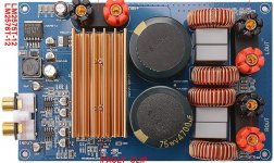
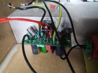
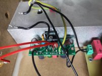
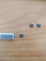
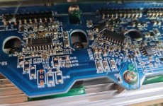
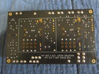
Beginner's Chip Amplifier, HiFi LM1875, The Amplifier Board
This is for the purpose of an accessible hifi chip amplifier, it is in reference to
Commercial complete Gainclone kit for a beginner? - diyAudio and it is by request. Here's LM1875, at low cost, and
easily made by following the "play by play" photographic format (starting at post#24). The LM1875's "only 5 pins hookup," and the absence of spike system noise, can give you 25 watts per channel of high fidelity, at a bargain price, and with an easy time of building your own amplifier.
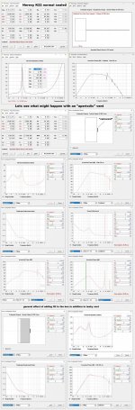
But, first, let's have a look at how "not" to use the LM1875: If you're planning the maneuver of pushing inefficient speakers with great force, then try
something else. Our introductory LM1875 project here, has not been
paralleled to withstand 4 ohm speakers.
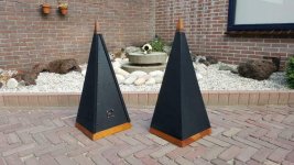
LM1875 works great with efficient 8 ohm or 16 ohm speakers: Since this thread starts from Gychang's post and since he is famous for the full range hifi genre speakers, then I think that the laid-back hifi sounds of LM1875 could be a perfect fit. Any reasonably efficient 8 ohm speaker is suitable.
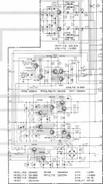
Circa 2012 update
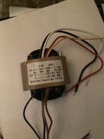
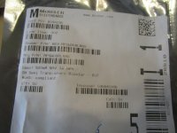
Suitable transformer voltage is actually 18+18vac or less. These transformers are affordable:
Antek - AN-0518 Monobloc/dualmono build is recommended for current control and wider imaging. For good longevity don't give an LM1875 chip access to more than 1a~1.5a worth of transformer. That's why Monoblocs really make sense.
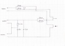
Input load resistor should actually be 10k (not 15k).
Due to lack of NFB-shunt cap, consider adding
high quality output cap assembly, in series to the speaker, for long lasting speaker protection.
Adjust capacitance value to suit speaker size for enhanced headroom. Output caps strongly recommended if using irreplaceable speakers with Any chip amplifier kit or project.
(click this link to see older nearfield design). The 2012 edition is a slightly refined version of the circa 2008 original, and suited to studio mixer/desktop use.
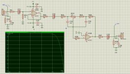
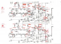
Circa 2013 update
With its gain of 34X, a computer sound card or digiplayer can drive this amplifier easily, without straining the source device. Now for 2013, it does have the NFB-shunt cap so it can't amplify DC. The
parts paralleling shown is for high end quality at low cost. Output caps are no longer shown on the schematic but they are fun to use for bass and headroom enhancement. Tone option: To compensate for a peakish speaker, add just ONE of
this model 4.7u from V+ to V- (rail2rail cap) at the amplifier board's power circuit to cause quieter midrange with higher resolution. Mains fuse and speaker jack fuse are suggested. Each monobloc produces up to 25 watts of power to an 8 ohm speaker.
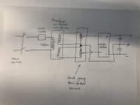
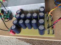
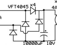
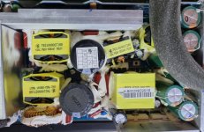
Power Supply
Here are CRC power supplies for these monoblocs:
Option: You can use 3300uF 35v or 50v caps, such as
Nichicon FW or
Panasonic FC.
Transformer Voltage
Example transformer voltage is 18+18vac
Click on best match for your application to see a hookup diagram.
♦
Your mains is 120vac and your transformer is 18+18 or less?
♦
Your mains is 230vac and your transformer is 18+18 or less?
♦
Your mains is 120vac and your transformer is 36+36 or less?(dual primaries in series)
♦
Your mains is 230vac and your transformer is 9+9 or less?(dual primaries in parallel)
(please assure that the transformer output is 18+18vac or less)
And see
Decibel Dungeon for a briefing on how to power your audio amplifier, including construction and safety.
Transformer Amperage
Greater durability can be had via good design and a right-sized transformer, or you could use a lot of fuses.
Monobloc/Dualmono:
♦ 36va*0.67=24 watts, which is perfect; however, we might want to adapt to dual secondaries and twin bridge rectifiers to maximize the little 1 ampere transformer. Use a mains fuse.
♦ 50va*0.67=33 watts, which is a bit too much; however, that's safe if given a Center Tap transformer (just one bridge rectifier) And the CRC power supply. Use a mains fuse and speaker jack fuse.
Stereo:
♦ 100va, instead of breaking chips, you may choose to use mains fuse and rails fuses for right channel amplifier board and rails fuses for left channel amplifier board and speaker jack fuses for each speaker. No matter if stereo or monobloc, a minimum of 7 fuses is mandatory if the transformer is greater than 50va.
Before powering on the new amp
Here's AndrewT's checklist:
Have you powered up via a bulb tester?
Keep this bulb tester in circuit until AFTER you have completed all tests and proved you have everything wired up correctly.
Have you powered the transformer alone and checked you have it wired correctly?
Have you powered up the transformer and rectifier and checked you have it wired correctly?
Have you powered up the transformer, rectifier and smoothing capacitors and checked you have it wired correctly?
Have you powered up the transformer, rectifier, smoothing capacitors and one channel of amplifier and checked you have it wired correctly?
Have you shorted the amplifier input and checked you have near zero output offset?
Have you measured the output noise with the input short in place?
Have you removed the input short and re-checked the output offset and output noise?
Have you connected your source and re-checked the output offset and output noise?
Have you tried moving the volume control and switching the source off and on and checked the output offset during all these changes?
Now you are ready to connect a dummy load.
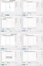
I would also like to suggest putting a
capacitor in series with the speaker for protector. It costs less than replacement speakers. And you get the Bonus of fun bass efficiency tuning for maximized headroom (a lot more power), by simply reducing the capacitance size to match what the speaker can do and roll-off what it can't do. This makes your amplifier output only what the speaker can use. Cheaper: If installed at speaker ground of a stereo build, two speakers can share the
protector.
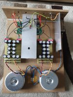
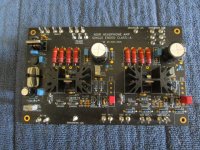
Avoiding destruction
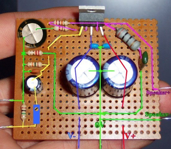
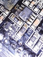
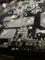
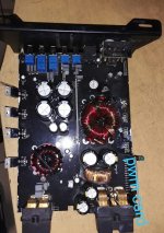
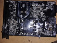
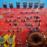
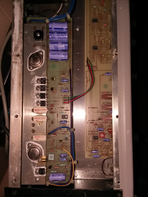
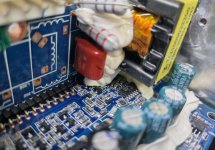
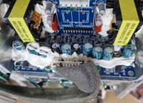
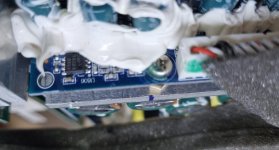
It may be very difficult to get up and running without the NFB-Shunt Cap, so here's a photo of the old 2008 project re-fitted for greater durability and so it won't amplify DC. This added part, NFB-Shunt Cap is the electrolytic
cap in the upper-left corner pictured. Whatever else it may do, it is absolutely certain to give you better odds at building a working amplifier. So, use it.


