I was doing ok with this today untill i came across, something i dont understand so maybe someone can assit to enlighten me
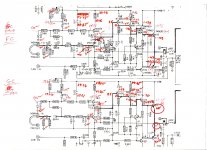
the 2 ringed vales,both are 0v and not what i expected as this is the the good channel
the issue is with the centre voltage(again @-144mv), which isnt the issue as im working my way through it, its the fact the these 2 values are not what i expected.
Q 602 B/E voltages are the wrong way round on the diagram, but couldnt change the upload before i realised.
Attachments
Last edited:
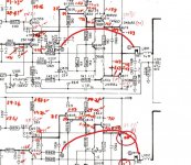
Can't just see R661/2 but the arrows mean it goes to ground.
D605/6 would modify the characteristic of the bias generator (vbe multiplier). Removing them is typical of a production change.
If the channel with 0 volts on the emitter of the outputs is working OK then its fine. 0 volt is the correct value. Anything else is classed as a DC offset. -/+100mv would be considered acceptable for such an amp.
The two ringed 'zeros' are perfect as long as that channel works.
The arrow heads pointing downward are grounds.
I couldn't see those resistors at first but as mentioned, those arrows and the C mean they are in electrical contact with the other C as shown here.
There might be no voltage across R661 or R662 if the thermal breaker is open circuit and you have no load connected.
Attachments
They are feedback resistors - if DC offset is close to zero they won't have much voltage. Seems to be two feedback paths, one before the relay to close the loop when the relay's open. The one after gives more accurate sensing of the actual output voltage typically.ok i will plod on, just thought it was a bit odd with no drop across those 2 resistors
Last edited:
A question to this circuit:The two ringed 'zeros' are perfect as long as that channel works.
The arrow heads pointing downward are grounds.
I couldn't see those resistors at first but as mentioned, those arrows and the C mean they are in electrical contact with the other C as shown here.
There might be no voltage across R661 or R662 if the thermal breaker is open circuit and you have no load connected.
is the use of D605 in the Vbe multiplier necessary due the absence of the emitter resistors for the BjT output power devices ?
check out also this threads:
Nad 3020 Issues - from a newbie
NAD 3020 transistors position.
P.S.: R647+R641 (for idle current adjusting by changing the value) instead a pot resp. variable resistor is a good idea, because such variable resistors provide often issues due the age, particularly in cases, where R645 is a pot.
Last edited:
D605 must have been thought necessary by NAD at some point and is related to keeping the bias current stable. Where it is located physically and by how much it heats up in relation to what is around it will determine its effect.
It is all done for stability and preventing thermal runaway (a very real issue with no Re's fitted). Whether it was added in later production or removed in later production I wouldn't like to say. Maybe it over corrected and caused distortion and so was removed.
Fixed resistors are my preferred option for bias setting but it is not really a suitable method for mass production if you want to aim for a certain figure of current.
The two ringed 'zeros' are perfect as long as that channel works.
The arrow heads pointing downward are grounds.
I couldn't see those resistors at first but as mentioned, those arrows and the C mean they are in electrical contact with the other C as shown here.
There might be no voltage across R661 or R662 if the thermal breaker is open circuit and you have no load connected.
of course what an idiot i am
I've only 'seen' D605 / D606 is early photos of the original 3020, they weren't present in any of several 3020's I've worked on, their pcb positions were always just jumpered.
In a similar vein, some 3020 schematics show a 6VAC 'tap' powering the LED power indicator, again, I've seen a photo of one, but never come across one - I think there were plenty of 'on the fly' production changes to the 3020 as it evolved... so it's not uncommon to find discrepancies between the schematics and what's actually there.
In a similar vein, some 3020 schematics show a 6VAC 'tap' powering the LED power indicator, again, I've seen a photo of one, but never come across one - I think there were plenty of 'on the fly' production changes to the 3020 as it evolved... so it's not uncommon to find discrepancies between the schematics and what's actually there.
The two ringed 'zeros' are perfect as long as that channel works.
The arrow heads pointing downward are grounds.
I couldn't see those resistors at first but as mentioned, those arrows and the C mean they are in electrical contact with the other C as shown here.
There might be no voltage across R661 or R662 if the thermal breaker is open circuit and you have no load connected.
i did check these early on, both breakers are ok and made
well i havent tried it in anger,ie with speakers
i am just working my way through things and comparing what i have already so im going to concentrate on that for now as i feel i am close.
one weird thing tho(see attached)
when i went to check the idle current, the 2 named resistors R653 and R654 dont exist on the board, they are just jumper wires, so not much point in putting a 1k resistor in parallel with a jumper wire.
ive worked on 3020's before ,but this one is weird.
Attachments
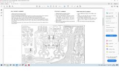
Sounds like there have been a lot of production changes in the models life. To check the bias current you will have to break the circuit to either the collector of the NPN output transistor or the collector of the PNP one. It doesn't matter which. Then solder a 1 ohm in place across the break and set for the correct current by calculating using the voltage across the resistor.
30 milliamps for example would be 30 millivolts.
30 milliamps for example would be 30 millivolts.
This might help - but remember your specific amp may also differ slightly, so check...
Nad 3020 work including idle current adjustment | Audiokarma Home Audio Stereo Discussion Forums
Nad 3020 work including idle current adjustment | Audiokarma Home Audio Stereo Discussion Forums
Sounds like there have been a lot of production changes in the models life. To check the bias current you will have to break the circuit to either the collector of the NPN output transistor or the collector of the PNP one. It doesn't matter which. Then solder a 1 ohm in place across the break and set for the correct current by calculating using the voltage across the resistor.
30 milliamps for example would be 30 millivolts.
so i took the 2 no trimmer pots out because something was bugging me about how loose they felt.Trickly little devils to take apart, but i did the first one,cleaned it up and put it back together.
The second one didnt need taking apart as it fell to bits, so i cleaned it up and put it back together.
A little tip for anyone who doesnt realy take things apart,i do frequently.
picture attached showing how they are fixed at the back, 2 little tabs bent over secure the whole thing, just carefully lift them back and you are able to get to the track to carfully clean it with a soft cotton bud and servisol, or other cleaner
so now both channels off set are pretty symetrical with thier outputs at pretty much 0v +/- 2mv and voltages around all of the transistors is also pretty consistant.
ive been using it now for about an hour at various volumes and seems ok ,so once again thanks for all who advised on this one
 , but im starting to get alot more methodical now so hopefully i wont have to keep bothering you guys all the time.
i guess it still takes me alot longer at the moment as im still not brill with the maths bit and i tend to find out whats wrong by just testing and checking
")
Attachments
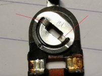
Those little presets can be very flaky sometimes. If the rivets are loose where they grip the ends of the track then you have problems. Think of your simulations and the vbe multipliers. Think how little change is needed to massively alter the bias current. So a flaky connection can play havoc with the setting long term.
The resistor you add to monitor the current would be around 1 ohm but it needs to be something very low so as not effect the operation of the circuit. You would unsolder or cut the supply to either output transistor collector and bridge the gap with the resistor.
The resistor you add to monitor the current would be around 1 ohm but it needs to be something very low so as not effect the operation of the circuit. You would unsolder or cut the supply to either output transistor collector and bridge the gap with the resistor.
- Home
- Amplifiers
- Solid State
- NAD 3020 problem