Yamaha M-80 Rebuild

Hi all,

I recently picked up a Yamaha M-80 amp that is in beautiful cosmetic shape but needs some work. I disassembled it tonight and found one blown output transistor, which is a Sanken 2SA1169 (code 63P). All the other outputs are fine. What do people recommend in terms of replacing it? Should I try to find one on eBay? That is never my preference, but there do seem to be some U.S. sellers that claim to have NOS replacements for about $15. Not cheap, but I'd do it if that is the best option.

I'm definitely going to have other questions as I go through this process, so I thought having a clean thread would he helpful. Thanks for your help in advance.

Calor amp 40 Watts Class A

Has anyone built this amplifier???.I am curious.Thank you

> Average output power--------40W/8 ohms (without exiting class A!)
> Power Bandwidth-------------11Hz - 135kHz
> Small signal frequency BW --- 2,5Hz - 450kHz
> THD----------------------------<0.008% (20Hz-20KHz/80%power)
> Phase shift --------------------up to 2,5� in the range 20Hz-20kHz
> Slew rate----------------------85V/uS
> Dumping factor---------------->750

Attachments

  • CALOR-schem.gif
    CALOR-schem.gif
    20.9 KB · Views: 4,878

Focal woofers, 7c4251

who needs a project! not I, so
we have 5 focal woofers that need a home...
1 used (it's partner was blown by son, I was so proud). Sound was excellent in QLN cabinets.
2 new without box
2 new in box, wrapped to nicely

I intended to do an MTM design, but there are enough for 5 speaker in surround sound.

shooting for 60 each, but all for...
offers please!

Attachments

  • IMG_20190907_203629017.jpg
    IMG_20190907_203629017.jpg
    805.4 KB · Views: 279

uA100 Class A/B BJT 100watt Design

Seems Im going through a 100 watt phase.
Really enjoy simple to some what complicated designs in the 100 watt @4ohm
power level. Or basically class AB with 35 to 38 volt rails

Also really enjoy lately the performance in simulation
of Fairchild 2SA1381 / 2SC3503 Transistors

Sold as KSA1381TSU and KSC3503DSTU
manufactured by On Semi through the usual distributors

This whole design started as a comical joke to myself.
Since these transistors seem to have good linearity
and high fT around 150 MHz.
I thought to myself ...
what if I just made a whole amplifier with just these transistors.

Would almost seem odd making a
Input stage, Vas and driver stage all with the same transistor.
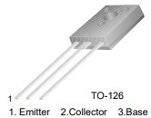
Also since its a TO-126 package
attachment.php


Well it actually started not sounding too crazy
since I like using current mirrors and current mirrors as current sources.
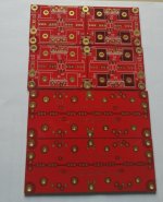
Ideal with board design it would be nice to thermally bond
the current sources, current mirrors and differential stage transistors.

So with a T0-126 package it would be rather easy
to mount them back to back.
And could be held together easily for what would seem
a pretty easy way of thermally bonding a transistor pair.

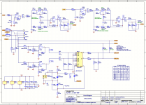
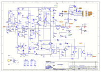
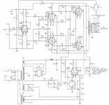
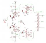
So be it. I decided to put together a Model in Tina TI
and see what a hysterical failure a all T0-126 amplifier could be.
Aside of course output devices be typical 247 or 264 packages for high current.

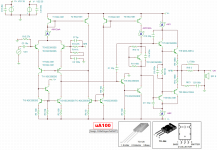
Im using MJL3281 / 1302 T0-264 packages for output devices

So I put together a basic design, which actually went rather well.
And with pretty standard capacitor values and minimal resistor count.
Got a sinewave to appear 🙄 LOL.

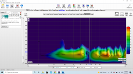
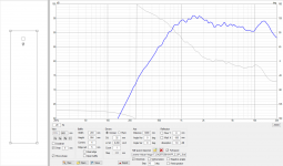
So I tapped the Fourier Analysis function in Tina TI
and it seems as if my Comical Idea is not much of a joke.
With 1 volt RMS input for full clean power at 8 ohms.
1 kHz harmonic distortion seemed to be .005 % 🙂

attachment.php


If I lower the compensation capacitor values a little bit, and remove stability network
on the output I can get it down to .002 % @ 1kHz

But in real life I will likely stick to higher values for stability.
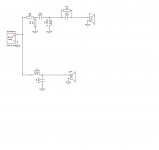
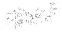
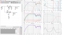
Using values shown in posted schematic/ screen shot of the TINA TI model
with the usual output stability networks

attachment.php


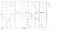
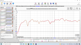
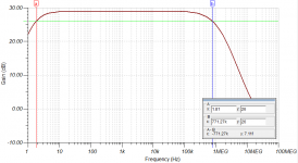
Frequency response seemed pretty good
Gain is set to around 29 dB so -3 dB response is around
1.8 Hz to 771 kHz

attachment.php


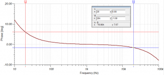
Phase in audio band around 6 deg @ 20 Hz and -1.59 deg @ 20 kHz
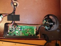
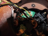
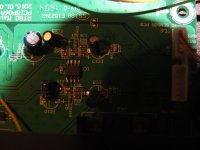
attachment.php

Attachments

  • KSA1381.jpg
    KSA1381.jpg
    6.2 KB · Views: 515
  • uA100 Fourier Series 1k.png
    uA100 Fourier Series 1k.png
    10 KB · Views: 593
  • uA100.png
    uA100.png
    89.8 KB · Views: 561
  • uA100 Frequency.png
    uA100 Frequency.png
    22 KB · Views: 579
  • uA100 Phase 20_20k.png
    uA100 Phase 20_20k.png
    18 KB · Views: 531

CHALIZE AMP

Hello

I have an amplifier CHARLIZE 2 from diyparadise - ... where we have more fun! ...

It is in a DIY box with speakers and rca connectors.

The power supply is not included in the box beacause i used it with a 12v battery.

If you are interested i can make pictures .


Your price will be my price plus shipping

Best regards

Serge

Attachments

  • charlize_aircore.jpg
    charlize_aircore.jpg
    57.8 KB · Views: 213

If UNSET and the RCA50W Had a Baby

What's UNSET? See here. It's a clever way of wrapping series-applied voltage feedback around an output stage and sharing some of the idle dissipation in the output stage between a mosfet follower and the output tube (which can get you more power if you increase B+ accordingly), apparently recently discovered by Mr. Tubelab and Mr. Smoking-Amp nearly simultaneously.

What's the RCA 50W amp? See attached schematic.

It's a 50W push-pull amp with three nested feedback loops that apparently can do 50W@0.1% THD, which ain't too shabby. The innermost loop is parallel-applied voltage feedback from plate to grid of the output tube. Surrounding that is series-applied voltage feedback from plate of output tube to driver cathode. And then there is the global loop that goes from amplifier output to input tube.

I've always had mixed feelings about this amp. It has a lot done right, but my back-of-the-envelope calculations show that the ouput tube plate to driver cathode feedback can't be very effective due to the fact that the low impedance load at the plate of the driver spoils a lot of the potential driver gain. Driver cathode degeneration lowers gain further. I'm not even totally sure that it has more gain than the gain that is trying to be set with the resistor ratio that is there.

Anyway, I've been playing with output tube plate to driver cathode feedback and have been having exceptional results with high gain drivers. It makes me wonder what would happen if we fixed the RCA amp a bit and used series-applied voltage feedback around the output tube instead of parallel-applied feedback, so I decided to run with that idea and I have attached a simplified conceptual schematic.

I made the output tubes two KT88 UNSETs (UNPPTs?), which frees up the driver to use a very high impedance load and develop some serious gain. Oh yeah.

This is pretty similar to my driver for my recent 826 SE amp experiments, only I reversed the input and feedback connections to make the phasing correct for negative feedback. Bias on the 6BN11 stage is not very stable over time due to absurdly-high gain, so a bias servo is probably mandatory on that stage. Open-loop gain of that stage is ~2600. This provides a lot of feedback and I expect resulting driving impedance on the primary of the transformer will be somewhere between 10 and 20 Ohms. Using a Hammond 1650R (or something with similar low copper losses) will result in a Zout of ~0.5 Ohms or so. Distortion will be extremely low.

In my mind, at that point, global feedback is optional, so I have omitted it. It could be added back in with another gain stage. I also like input transformers for the immunity to ground loops that they offer so I included one. Obviously, I have omitted some necessary components such as stoppers, protection diodes, and something to tie input transformer secondary to some level other than what the leakage currents pull it to.

The UNSET output configuration offers the opportunity to share some of the idle dissipation between the mosfet and the power tube, so I have increased B+ to 530V. This still puts 450V across the output tubes like in the RCA amp, but now we can hit over 75W with the same class of output tube, and have plenty of idle current to keep idle output tube transconductance high.

I decided to pull the output tube plate to driver grid feedback network down near GND with a CCS. My intuition tells me that having a high AC impedance at this node would have a balancing effect on the amplifier. I'm not sure how well this would work (haven't simmed it or anything). The other option would be to ground the center point (maybe with a trim pot in the center to adjust out AC imbalances in the two halves).

Anyway, I think it would make a good amp that could make your ears bleed with low distortion.

As always, comments/criticisms welcome.

Attachments

  • RCA Original.jpg
    RCA Original.jpg
    160.9 KB · Views: 1,889
  • RCA_50W_CCS.jpg
    RCA_50W_CCS.jpg
    115.8 KB · Views: 848

Help with op amp layout

Hey everyone, working on my first audio circuit and am questioning my layout. I don't have a breadboard to test the circuit before soldering so figured id come ask here before I solder everything up and end up with an AM receiver. Attached is the schematic I am going off, and the layout I have spent way too much time on, haha. Any input greatly appreciated!

EDIT: Please ignore my mislabeled 1K and 100K resistors

designing_headphone_opamp_amp_clip_image019.jpg

Untitled-1.jpg

Really soft HT start for DHT amp

I"m looking for a circuit that will provide a gentle HT rise to 400V over 3 or 4 seconds after the filaments are ready to go in an existing DHT amp.

I've tried a relay delay and MOSFET soft-start but the rise time is around 250ms which causes a single cycle of 4Vpp around 1Hz to appear at the output. That would be bad news for the unloaded full range drivers.

The ideal solution would be a tube rectifier. Unfortunately, that would require a new mains transformer and a lot of re-work.

Does anyone have any suggestions please?

Test LP group buy

This is a spinoff from the Turntable speed stability thread. Here we can discuss the technical details and logistics of a future test LP creation and group buy. Especially:

- Signals of the tracks at both sides
- Tools for signal generation
- Selecting the mastering/pressing company
- Organizing group buy
- Options (half speed mastering, etc)
- Any other ideas

We could have a brainstorming what type of test signals are available on other test discs, what of them are useful, what is missing. I believe it should be a measuring tool, so e.g. L/R channel identification and the like are unnecessary.
-------------------------------------------------------------------------------------------------------------------------
Suggestion of tests by Pano
-------------------------------------------------------------------------------------------------------------------------
Track list by luckythedog
-------------------------------------------------------------------------------------------------------------------------
Collaborative folder on Google drive
-------------------------------------------------------------------------------------------------------------------------
Sign-up sheet on Google drive
-------------------------------------------------------------------------------------------------------------------------
Tracklist on Google drive - updated by Pano (see latest version below)
-------------------------------------------------------------------------------------------------------------------------
Test LP Progress Tracking
-------------------------------------------------------------------------------------------------------------------------
Updated tracklist by Pano

WTB : CD4013, CD40106, CD4001 and IRF93

Hi,

Looking for someone in North America that could sell me these parts

There's no stock of the IRF9530 anywhere (at least Digikey or Mouser) and I don't want to buy from fleabay because I don't want to take the chance of getting a fake one...

If anyone has 2 of them I would gladly buy them

As for the ICs (CD4013, CD40106, CD4001), I also prefer original ones or known brand. Again don't want to buy from fleabay. Mouser has stock but 20$ shipping for just ~6$ purchase is not ideal...
Mouser part numbers below (looking for 2 of each)
595-CD4013BE
595-CD40106BE
595-CD4001BEE4

Thanks
Do

Port length for microTower

Hi
I'm almost certain this is a dumb question, but I can't work out what I'm doing wrong. I'm currently building a pair of the Microtowers from the frugal-phile website using the Pluvia 7HD. The port for this is specified as 3 inches diameter by 4 inches length. The pipe I have for this is 80mm internal diameter. It seems unlikely that that would make much of a difference, but to check, I've tried to re-calculate the port-length using the equation Lv=(23562.5*Dv^2*Np/(Fb^2*Vb))-(k*Dv) (as recommended in the plans). When I do it though, it tells me the port should be over a metre long. Where am I going wrong?

Replacement transistors, NAIM NAP90

Hi all,

I have a great sounding NAP90 power amplifier. However, one channel has been shorted and a few transistors are burnt and need replacement. The one on the NAP90 are kind of obsolete, so I thought I might upgrade them in this occasion and make it better...

The ones which has burnt out are:
ZTX652
ZTX752
J13009-2 (power transistor which has been used instead of the stock ones)

Also I saw that one ZTX348C has it case broken.

Can anyone point me to any replacements that will fit, and sound at lease as good ??

Thanks a lot !

Parallel Push Pull 6AS7 or 6080

Hey guys,

A few months back I posted a thread about a push pull Rauland Borg PA amp which had an OPT with 6.6K primary and a 500 ohm secondary (As well as 250, 166, 80 ohms as well). It used a pair of 6L6's as the output. I am trying to convert it to a parallel push pull 6AS7/6080 amp. I have worked up the attached schematic and was looking for some thoughts. I plan to start working on it this weekend.

Sorry for the not s great pdf. Scanner is having issues but I think it is reasonablly readable.

Thanks in advance for any comments.

Attachments

Let's talk DIY pro outdoor Bass Bins!

I was asked by a friend to start looking into building him outdoors, PA speaker system for EDM and Techno music.
This require good bass extension. Most of the gigs, live bands or DJ, would be outdoors and there would be from 1000 to 5000 bass lovinnn teens/ young men.
I diy'd a few JBL Scoops (4530) copies and am familliar with building those. 4520's with their dual 15inchers would be too combersome/ heavy but i was thinking either modified 4530's or, similar design for 18inch pro subs.

Now, are these scoop styles a thing of the past, for PA (the low bass), and ease of transportability OR, should forget about those and think ''W'' bass bins???.
My friend is renting the equipment right now but wants to own a system, that can be augmented with the needs.
I was thinking about used or new Crown amps and active x-overs.

The scoops may only require a 3way settup but the ''W" bins would require 4 ways right?.
The scoops are easy to install close by for mutual coupling and, the front of the drivers would take care of upper bass.
I am leaning towards scoops but need the advise!.
Mids would probably be front loaded 12inch cone drivers.

New 2way bookshelf and crossover

Starting a new project of a 2way bookshelf speaker

Enclosure Details :16 Liter (after excluding volume taken by driver, port tube, and bracings) with a 2 inch diameter x 7 inch long port tube, tuned at 42Hz.

Drivers : 1. Peerless NE180W-08 woofer
2. SB Acoustics SB26ADC tweeter.


Me and my friend came up with two crossover designs. Crossover frequency is around 1.5kHz-1.6kHz.

Crossover I :

Attachments

  • P+ SB26 ADC FR.jpg
    P+ SB26 ADC FR.jpg
    189.3 KB · Views: 705
  • P+ SB26 ADC Impedance.jpg
    P+ SB26 ADC Impedance.jpg
    166.7 KB · Views: 657
  • P+ SB26 ADC Components.jpg
    P+ SB26 ADC Components.jpg
    67.8 KB · Views: 667
  • P+ SB ADC.dxo
    P+ SB ADC.dxo
    73.5 KB · Views: 75

Audio signal detector

I try to make a circuit that when the audio signal is present automatically opening the amplifier and when the audio signal is discontinued closes the amplifier after a certain period of time. I made a circuit as follows, works on breadboard.

I don't want to join the circuit power ground and signal ground.

How can I do better.


its google translated.

Attachments

  • Untitled.png
    Untitled.png
    3.4 KB · Views: 128

Pyramid PR3000 Electronic Crossover?

Please don't laugh me off the forum: I have had pretty good luck with an electronic crossover from - gack! - Pyramid.... (I've also seen the same thing sold with a different name.)
One source (of many):
http://www.audioblowouts.com/Dj_Equipment_Pro_Audio/Rack_Mount_Crossovers/Pyramid-PR3000-6491
I know, ratty stuff, to be sure. But here are its advantages: Usually found for about $55-$65. Totally flexible, once the resistors are changed to suit your needs for crossover frequencies. Three-way, 12dB per octave, stereo crossover. Ranges can overlap. Uses RCA inputs and outputs. No turn-on or switching thumps and pretty quiet, reliable operation overall. Power supply and connectors easily upgraded (easy to disassemble and reassemble). Cosmetically quite acceptable. Switches and pots feel OK. 110V. Rack-mounted.
Realities: What do you expect for $55? It uses a crude inline op-amp package, so no real hope of upgrading them (Please prove me wrong!). Five FIXED frequencies for each range: these will need to be changed by swapping out the frequency-setting resistors (but that's a good exercise in active filter design).
Bottom line: With some simple resistor swaps, can be a useful tool in evaluating crossover frequencies and drivers. Not for serious audiophiles, but not total cr@p, either...

Tosh

Marantz 8 B : Output Transformer

Hi all ,

I'm planing to build a Marantz 8 B CLONE , for my own use .

Does anyone knows the impedance ( PLATE TO PLATE ) of
an original Marantz 8 B output transformer ???

And the TURNS RATIO of the screen grids taps ( 10% , 33% ,
43% or what ... ??? )

I already have the original Service Manual , and this is the
only data that I do not have yet .

Thanks in advance for any input .

Regards for all ,

Carlos

Oscillating Amplifier

Hello
Looking at the Attached Circuit, I would appreciate any comment as to why this Guitar Power Amplifier circuit does not have any sort of Zobel Network on the Output Terminals. This Particular Amp I am working on is suffering from an amount of high frequency instability, and I was thinking that it might be appropriate to add one?
Thanks for any insighthttps://www.diyaudio.com/forums/attachment.php?attachmentid=961398&stc=1&d=1624257194 -Telnet100

Attachments

EL34 Baby Huey Kit GB 2021 Builders

Hi. I'm starting this thread for the members of the 2021 GB PCB kit. Please post your progress. You can discuss any issues related to parts, and to see if there is any problem with the PCB, and their solutions. We never know with a new built pcb, errors are always possible. Also if you find any interesting mods, please share it with the group.

Happy built!
SB

Dynaco ST-70 rising bias

All,

I have a challenging and rather unique bias issue I cannot solve. The issue resides only in the right channel. And here is the problem.

When you first turn the amp on, the bias is stable. I keep my voltmeter connected to the right channel only and bias is rock steady 1.25 volts. If I take my finger and rotate the tube around the socket without disconnecting the tube the bias voltage begins to rise and will keep going past 2 volts. (I never let it go beyond 2 volts) If I take the voltmeter and check the negative grid voltage on the near side .1 uf capacitor it shows something like -20 volts then increases to -31 volts. Then when I recheck the bias voltage it is back to the original value of 1.25 volts and remains at a steady state. Also, if I turn the amplifier off and wait two minutes or so and turn it on the bias is perfect once again. The left channel does not exhibit this behavior. I built the new card from Dynakit and it has been a flawless board up until this problem arose. The board is well constructed and I would buy another. I have done the following for trouble shooting.

Replaced tube sockets.
Replaced near side .1 uf capacitor
Installed new tubes drivers and outputs tubes and even installed the original 7199's (same problem with the 7199's in the right channel)

Polished tube pins
Deoxit tube sockets
Re-tensioned sockets

Fixed and re-soldered many joints in right channel signal path and more
Checked continuity on every trace directly to the tube sockets
Check voltages and all are in specification.
Checked the bias supply and it is healthy
Checked for cracked traces, none found and checked continuity hot and cold. There are no issues.
New power transformer in 2017 during rebuild.

So, does anyone know why one channel would be affected? More like only one side of the right channel, but since the bias is tied together it is hard to say. It is almost as if there is some sort of gremlin that caused the capacitor to build up some type of opposing charge and the DVM discharges the negative side through the meter.

I am open to anyone's expertise so that i don't have to work about bumping the right driver tube and have a runaway bias situation. Right now I have my voltmeter almost always connected.

Thanks to anyone in DIY forum that has experience with this issue short of replacing the driver board.

Pi and the outrageous Xmax

During a debate I highlighted the negative aspects of drivers with a large Xmax, inefficiency, sluggish response. I intimated there was a 'sweet spot', the ratio between Xmax and driver diameter. I used a piston engine bore / stroke as an example.

Certain members lost their minds!

To further my case I have made another observation which supports the case against. I have 6.5" driver with a ridiculously large Xmax, however, due to the large surround to accommodate the increased excursion, the diaphragm of the sub is smaller than that of a comparable 5" Hi-fi woofer.

I'm suggesting that in reducing the diaphragm size to accommodate a large Xmax you're simply producing a driver that requires more power to achieve the same result.

I'd appreciate somebody looking into the math on that.

Kelly KT3 Crossover Upgrade

Hi, not my first project but my first post.
Kelly KT3 90's vintage (manufacturer Musical Fidelity) high sensitivity floor standers. Twin bass/mid drivers in parallel, one in the top chamber rear ported and one in the lower chamber front ported.
Drivers 2 x Audax HM170Z12 1x Vifa 96db sensitive tweeter (Scanspeak & Peerless make an current equivalent)

I have looked at the crossover. Schematic here:
An externally hosted image should be here but it was not working when we last tested it.


Interestingly it is the same board layout as Kelly KT2. But there are resistor differences between the two and the Kelly KT2 Audax drivers are HM170ZO

Q: The resistor R3 is Red Red Gold which I think is 2.2r so the circuit is 1 ceramic 2.2r @ R2 followed by same value different resistor type. (KT2 have a 0.22 ceramic there so reason I am confirming value)

Definitely upgrading the ceramics with Jantzen,Ohmite,Mills some such like but is R3 worth changing? Is it likely a carbon or film?

The LF cap C1 in the image has a rating of 20mF. Pretty sure it means manufacturer didn't have a mu sign and it is not micro Farad. Can anyone confirm my thinking?

Many thanks in advance

Attachments

  • 2021-06-18_16-14-33.png
    2021-06-18_16-14-33.png
    17.8 KB · Views: 176
  • 2021-06-19 0.22.png
    2021-06-19 0.22.png
    203.7 KB · Views: 179

Marantz CD 63 MK2 Signature player laser replacement

The laser needs replacing. I have studied lots of "how to" posts on line, but before I proceed with this task I need some clarification. Advertised laser prices vary hugely. My experience with classic motorcycles has taught me that paying top dollar for parts is not always a reliable indicator of quality. Anyway I have digressed, let's get back on topic. it seems there are various types on offer, some with plugs on the ribbon cable for example. What I need to know is this: are these interchangeable with the Marantz plugs and sockets ? Some are shown as having a bare ended ribbon cable. All very confusing. I just want to ensure that I buy the correct unit

Nutube power switch question

Hi All,

I am still gathering parts for my Nutube B1K build. The only thing I lack is the power or on/off switch. I can see from the Pics that it is a 6 pin toggle switch. I am however, unable to identify the correct switch or configuration. So, does anyone have a part number or a configuration for the switch so I can buy the correct thing? I would not mind having a larger toggle or a push button switch.

Thanks

Removing a Jolida 502 Balance Control

I'm deleting the balance control on my Jolida 502A. Attached is the portion of the schematic (it's a 302 schematic, but this circuit is the same).

Also attached is a pic of the vol-bal board. It'll be deleted, since I'm also replacing the volume control with a TKD unit (but that's easy).

Can anyone advise as to the changes in the circuit to remove balance? Sorry for the ignorance, but it's been 30 years since I did this last.

Thanks!

Attachments

  • Balance Control.JPG
    Balance Control.JPG
    47.3 KB · Views: 264
  • Volume-Balance.JPG
    Volume-Balance.JPG
    47.5 KB · Views: 246

Bass Reflex with DSP - How would you optimize?

Hi,

I was planning on a bass reflex speaker. To find an optimum BR speaker one would typically load in a spreadsheet and decide on the allignment and there will be an answer.

I was just thinking to myself, there are many ways you can optimize differently if DSP involved. How would you optimize for such a speaker?

I personally would optimize it for the -6db point rather than the -3db point. Then I would probably push up the bass by another 3db at the 6 db point.

How would you do it?

Oon

Why do I get music with signal return disconnected, but not when connected?

Hey guys! Been searching the forum and reading for 3 days now, but can't figure out/comprehend what's happening in my situation.

It's a battery-powered boombox that uses an automotive head unit, 2x TDA7498s, and a Boost Converter to give the amps 30ish volts.

12v from battery goes to head unit and boost converter. All grounded to the battery.

If I use both wires for a channel, going to the amplifier, there is no music from the speakers. If I unhook one of them, it plays perfectly. I feel like it's some kind of grounding problem, but I clearly don't know enough about this to figure out my problem. I've been hooking up radios and amplifiers for over 30 years, now, and it blows my mind that I can get sound with just one wire!

What am I doing wrong? And what Is this phenomenon (in my eyes lol)?

Dayton DCS450 18” in W-Frame dipole?

Hey all. Looking to build a W-frame dipole woofer for the first time. $300 budget for the drivers. DSP will be used for EQ/roll-off correction. I came across the Dayton DCS450 18” woofer that seems like it might work ok. Thoughts? Do you guys have any other suggestions for a pair of drivers I should consider in the <$300 for the pair price range? Happy to go any diameter, but obviously with smaller woofers I’d be wanting extra xmax to make up for their size.

Was also looking at the Dayton DCS380 15” but this doesn’t have much more xmax and seems like not as good at the 18” version for the money.

JFet vs bipolar

Hi!

I'm from Denmark and is working on a highend preamp sparetime project.

I've been doing some listening tests of jfet vs bipolar transistors, and found some generel sound differences.
Jfets tends to sound softly, while bipolar sounds more dynamic.
Do you have any experiences like this, and which do you think sounds the best?

Regards
Asbjorn

8" Woofer Yamaha NS-A335

Picked up a pair of Yamaha NS-A335 at a yard sale for $4. Got 'em home, listened and boring sound. Pretty boomy. Opened 'em up, not much of a crossover. No inductor on woofer, 4.7uf on the mid, 2.2uf on the tweeter. Cab is about 23 liters. The 8" woofer looks kinda' decent though. Ribbed paper cone, cloth surround, in good shape. Any experience with these or NS-A635. Also an Optimus version. Rebuilt box, new front baffle with only woofer opening. Stuffed with polyfill but still boomy. No measuring capability here however woofer seems to go pretty high. Any suggestions or time to move on. Thanks.

Attachments

  • IMG_0080.jpg
    IMG_0080.jpg
    799.1 KB · Views: 172
  • IMG_0081.jpg
    IMG_0081.jpg
    766.8 KB · Views: 190

FS: DAC AK4497 kit

Hello

It is a DAC Kit bought two years ago .

The cms components are soldered.

There is no component in the kit for the power supply but all the others are in the kit.

if you are interested ,make me an offer + shipping ( I preferred in Europe )

If you have any questions do not hesitate

Thanks
Serge

Attachments

  • AK4497.jpg
    AK4497.jpg
    229.1 KB · Views: 373
  • AK4497-1.jpg
    AK4497-1.jpg
    180.7 KB · Views: 361
  • AK4497-2.jpg
    AK4497-2.jpg
    152 KB · Views: 354

Why capacitor explosed ?

Hi all,


I'm currently trying to make an amplifier, so for that I used the driver PCB from an Onkyo NR609, and I have build my own PCB for insert the PCB driver :


schema-Origine.jpg

schema-Origine-Final.jpg


schema.jpg


pcb.jpg

The PCB driver is inserted in the 9pin connector on my PCB. GND of the PCB driver is grounded via the pin above the 9pin connector.
The Bias transistor is in a hole in the heatsink.

I tested my amp yesterday for 30min with music without problem, the offset on the output was arround 2mV, nothing hot, all fine.. But suddenly the capacitor C5440 (on the original schematic) has exploded :/
I don't understand why... What can be wrong ?


FOR INFORMATION, I have not mounted the componants for the DC protection, so there are only the output stage, driver PCB and output filter mounted on the PCB.

DSP advice needed: MiniDSP 4x10 HD?

Hi,

I'm looking for a DSP with at least six outputs. At the moment I use a MiniDSP 2x4HD, but I would like to compare my 2-way hybrid loudspeakers with my transmission-line loudspeakers, so I need 6 outputs.

There's also the MiniDSP SHD, but this product has only 4 outputs and I don't need a streamer. There's also a 4x10 with Dirac, but I'm unsure if I would like Dirac.

Any ideas what alternatives there are? Would a 4x10HD a good choise for doing listening tests / comparing loudspeakers?

New RedRoo tube amplifier from Australia

Hi everyone

A couple of years ago I designed a 5W+5W stereo amp using 12AT7's and EL34's, and a solid state inverter power supply. The concept was to make a top quality SE tube amp which would be easy to build with little point-to-point wiring, and with a good looking pre-drilled chassis.

Over the past few years quite a few have been built and to my knowledge they are all performing as expected, so I've put the entire design up on the internet to see what happens. Sort of an experiment.

Basically I'm a retired electronics and telecommunications guy just doing it as a hobby business to have a bit of fun in between sailing and motorbikes. I'm selling pcb's, a chassis kit, and output transformers to whoever wants to make one, (you dont need to buy anything from me, but it would make life a lot easier).

The full information is at Tube - Valve Stereo Amplifier to Build Yourself | RedRoo Kits

I hope you enjoy reading. I'm now working on a guitar amp 🙂
Tube - Valve Stereo Amplifier to Build Yourself | RedRoo Kits

DATS V3 - Dayton Audio Test System

I am wondering about the results - or lack thereof - when I try to measure a Linaeum ET-8 tweeter. I get a value for the R(e) of 7.33 ohms and for L(e) of 0.02776mH only; and I get a nearly flat red trace (phase?) and a very flat blue trace (impedance?) that rises a bit starting at 5kHz.

Due to the design of this tweeter, what should I use for the piston diameter?

It does not allow me to go on to use Measure V(as).

To design a 2nd order (12dB/octave) crossover for this tweeter - do I need to know more data, than the R(e) and L(e)?

Fluance RT81 Turntable built in preamp true bypass

Hi everyone,
Not long ago, I bought a Fluance RT-81 turntable. Price is excellent and I said...can't be too bad, can it? The company offers a good return policy, so I went for it. I used it with its built in preamp, sounded decent, but not enough gain, it's very quiet (35dB of gain, Fluance told me) Then, I bought a Schiit Mani phono stage and the gain was excellent, but I noticed the high frequencies weren't ok, very recessed, sound was 'thick', if I could describe it like that. Did some research, and people experienced the same thing with Audio Technica tables with built in preamps. The onboard preamp is never truly bypassed. This Fluance exhibits the same thing. The signal seems to be passing through some capacitor on the main board no matter what. Another hint is the pop heard when powering the turntable on even on phono out.

I decided to mod it and somehow to make it reversible in case I'd wanna sell it one day.
The tonearm wires are soldered into a small board (Technics style but damn small) and from there other wires go to the main board/preamp into a small connector.
Removed that connector and the wires and kept it. Connected the RCA cables directly on that very small board (used some other small wires to bridge, found it hard to reliably solder RCA end onto that board) .Then connected an external ground wire to the tonearm base board and another wire to the ground post at the back of the table. I made an angled hole in the base and used silicone to secure the RCA cable in case of an accident.
See pictures!

I tested different things with the ground cables, and this worked best, so kept it. Now it sounds as it should. Happy I didn't blame the Schiit Mani and did not return it. It's very versatile and sounds great.

Maybe the work I did is not the greatest, I'm not that great with soldering, but it works.
Now I'm ok with the setup. Maybe a cartridge upgrade in the near future, I'm thinking AT440MLb. This Fluance turntable works great, has an auto-stop feature, which I find handy in case I leave suddenly or fall asleep to a record. I'm not one of those people who would spend thousands on a vinyl rig. One can get an excellent vinyl playback system for a few hundred dollars.

Attachments

  • DSCF1237.JPG
    DSCF1237.JPG
    347.8 KB · Views: 817
  • DSCF1238.JPG
    DSCF1238.JPG
    264.3 KB · Views: 716
  • DSCF1239.JPG
    DSCF1239.JPG
    375.8 KB · Views: 733
  • DSCF1240.JPG
    DSCF1240.JPG
    195.6 KB · Views: 715
  • DSCF1242.JPG
    DSCF1242.JPG
    303.6 KB · Views: 755

Simulation in VituixCAD - what did I miss?

To date I've built my speaker driver and circuitry design understanding to a level where, using VituixCAD, I can plug in some drivers, trace SPL/Z, make up an enclosure design, do some diffraction simulation, and finally start messing around with a crossover configuration that result in some nice looking graphs (in my opinion, anyway!).

Before I pull the trigger on some components I decided to validate what I've been doing by taking an existing design and simulate it and see if the graphs match what you'd think sounds normal, or even good!

The first thing I did was take Paul Carmody's Amiga MT and plug everything in as I've been doing. I traced the SPLs/Zs, did the baffle diffraction, then put Paul's exact XO design in to the XO tool. Curiously, the Woofer response looks ideal but the tweeter is a mess. I made an assumption on the 20mm Z position on the tweeter. No amount of playing with the tweeter circuit using the same layout results in a reasonable result.

Referring to the tweeter diffraction graph, it looks pretty tidy... The overall impedance is even a pretty close match. Is what I'm doing here an issue with me, VituixCAD, something else? 😕

Attachments

  • diyaudio1.PNG
    diyaudio1.PNG
    947.7 KB · Views: 330
  • diyaudio2.PNG
    diyaudio2.PNG
    463 KB · Views: 308

Is it possible to build a Dolby Pro Logic 2 system or better to buy prebuilt?

Is it possible to build a Dolby Pro Logic 2 system or better to buy prebuilt?


I read an old thread about Dolby Pro Logic 2 matrix scheme here but in that there was a objection against DIY version because it lacked the speed in steering. Is this still the main problem today too? Or can build something similar to it easily?

Heat sinking 300B LT1085 heater regulators

I'm working out details on a 300B build and am leaning towards using LT1085 regulators for the DC heaters based off this schematic.

My question: will mounting these regulators to the underside of a steel chassis with thermal paste/insulator kit be enough to keep them alive, or are they going to need a dedicated heat sink?

If they need a dedicated heat sink, I'll probably mount them above the top plate to keep their heat away from the caps etc. inside the amp, so would like to plan for that, if simply sinking them to the chassis isn't enough.

I'm sure a debate over A/C vs D/C heaters will erupt, which is fine once I get an answer for my heat sink question 😉

Attachments

  • 300B-5V-Regulated-Filament-Schematic.png
    300B-5V-Regulated-Filament-Schematic.png
    70.8 KB · Views: 550

Garrard Music Recovery Module Buzzes Loudly

Hi,

I got this unit, Garrard MRM-101, in its original condition. The unit buzzes very loudly, sounds like a 50Hz square wave tone which is my mains frequency.

The buzz happens about 1-2 seconds after turning on.

The buzz goes away when I turn on the suppressor but there's no sound coming from the turntable.

The grounding point for the phono seem a bit suspect so I replaced the push button with a speaker binding post to no avail.

My first thought is the mains filter capacitors are out so I will be ordering new ones - along with the other capacitors on the boards.

Has anybody came across this problem on the Garrard Music Recovery Module?

Garrard MRM 101 Music Recovery Module Manual | Vinyl Engine

No bass or out-of-phase bass, midrange and treble after swapping amplifier.

Lets say there are two 2.1 speaker sets


Speaker A has a wired remote control, with a 4" driver in a vertical sub-woofer, which can be placed away from the satellites.


Speaker B doesn't have a wired remote control, has a 4" driver in a horizontal sub-woofer, which is near field and requires to be placed near the satellites.


I wasn't satisfied with the sound quality of Speaker A, so I removed the transformer, board with amplifier from Speaker A and placed them in Speaker B.


Before placing Speaker A's internals into Speaker B, I removed Speaker B's transformer, board, etc from it.


Speaker B's board has two 4700uF capacitors, didn't have any SMD components but had connectors for cables, cables weren't soldered.


I replaced Speaker B's board mainly for the convenience of wired remote control of Speaker A. Speaker A's board only has 1 4700uF capacitor on it's board.


Although I cannot notice any decrease in loudness of mid-range and treble with Speaker A's board with Speaker B's satellites, sometimes, it sounds like they are out of phase. Both the satellites of Speaker A and Speaker B connected with RCA plugs, so I didn't think negative and positive were swapped.


But the main problem I'm facing now is the bass, I've soldered the negative and positive of Speaker A's board (sub-woofer output) to the negative and positive pins of Speaker B's sub-woofer driver, but bass seems out of phase, and it is very less, could this be because Speaker A's board only has one 4700uF capacitor? Or is it because Speaker B's sub-woofer is supposed to be near field but I'm placing it far away like or is it because of difference in shape of sub-woofers?

Longer ac trace or dc trace?

Im building an all in one preamp with pcb mounted trafos and trying to figure out the optimal layout.

The rectifier diodes, should they stay as close to the trafos as possible or to the smoothing caps?

In the 1st scenario i will end up with about 5cm dc traces from the rectifiers to the caps. In the 2nd situation those traces will carry AC.

Which one would be the better solution and why?

corner line array and SB10PGC21-4

Good day all!

I have recently finished a pair of 3 way dipole speakers. Still finetuning them, but also looking into speakers for another room, about 3.5m x 4.5m and 2.5m ceiling. The room is symmetrical and corner line arrays would fit in very well - so I tend towards these.

I read a lot through Wesayso's thread, also the corner loaded array from ra7 and got some of the Vifa TC9FD-8-18 to play with. I also ordered some of these new fullrange drivers from SB acoustics (about 12 euros each, excl VAT).

SB Acoustics :: 3” SB10PGC21-4<br><font color="#C70039">SHIPPING</font>

Is the lower Fs (89Hz instead of the 125Hz for the Vifa) an advantage? I think so?!

Does anyone know of a service, in Zwitserland or neighboring countries, that could provide me with CNC cut baffles? I am thinking plywood.

best regards!
Erik

3e Audio SY-DAP2002 DSP Programming Issue

Dear all,

Hope everyone is doing great!

I am facing this issue when trying to program 3e Audio's SY-DAP2002 DSP. I have connected the USBi connector to the amplifier board and in Sigma Studio Hardware Configuration page, I can see that USB is connected (green box).

The problem comes about when I press "Link Compile Download" button and the following error appears as in the attachment. Trying to change anything in the User EQ section also does nothing to the sound.

I have tried both SigmaStudio 4.5 and 4.6 and both have the same errors. Has anyone met this problem before and have a solution to it?

Thank you!

Attachments

  • Capture.JPG
    Capture.JPG
    261 KB · Views: 160

Arcam Alpha 8 Amplifier Crackle

Hi, I've taken an old Arcam Alpha 8 Integrated amp out of storage and unfortunately it has developed a fault. There's a constant crackling mostly on the left channel but also faintly audible on the right. It's also only faintly audible with the 'direct' button pressed to bypass the balance and tone controls. Could this be a faulty transistor in the left channel? Cleaning the pots hasn't made a difference and the noise doesn't change with the volume or with different inputs. Any help would be appreciated.

Attachments

  • Screenshot 2021-06-16 at 12.25.38.png
    Screenshot 2021-06-16 at 12.25.38.png
    179.4 KB · Views: 384
  • Screenshot 2021-06-16 at 12.27.22.png
    Screenshot 2021-06-16 at 12.27.22.png
    215.9 KB · Views: 361

3 way speaker design with this specs (HT oriented...)

Do you know any publicly available DIY speaker design that fits this bill:

1-. 3 way
2-. Waveguide loaded tweeter
3-. Home Cinema oriented
4-. Not full range (will use SW so over 60/80hz is OK, with good mid bass and lower mids)
5-. Available drivers and in stock
6-. Free/open design or available for a fee (like Heissmann Acoustics)
7-. Hopefully in a big monitor format (not a tower)
8-. Under USD$500 ea.
9-. Passive XO (for now, good active XO is over my budget --> USD$500 only for the amps and DSP!)

I've searched a lot for this, and could not find anything like it... maybe because it's not worth it? IDK. Maybe its better/cheaper to get 5x Kali Audio IN5 and call it a day.

Cheers

Amp for Axi2050

Hello, I am searching for an amp to power the said driver which in combination with the horn I'm using, sensitivity is somewhere around 112 to 114 Db

In a previously completely unrelated thread I learned about amps that might work for high sensitivity drivers in general...this completely different and unique thread is different from the previous thread. I am looking for an amplifier that will work specifically for the axi2050, in this thread, unlike the broad approach of my previous thread about amps for high efficiency drivers.

Ive never built an amp before...if I choose a build maybe I can get you guys to hold my hand?

My aim was for class a with neutral/transparent playback...no harmonic distortion commonly associated with some tube designs please

Help withTraynor 6400 Series 2

Hello. I'm completly new to this forum and a severe novice when it comes to electronics repairs.


I have a Traynor 6400 series 2 powered mixer. After hooking it up to new speakers today, everything was fine and then a couple hours later when I went to use a new mic with it, there was suddenly no sound coming out. I have since learned that if I turn the volume and gain all the way up, I get just the absolute minimum amount of sound. The led gauge is working and is even going as far as to say it is nearing maxing out, but it can obviously go louder than this. I've tried both speaker outputs in the rear as well as the main output in the front.


Any help is appreciated. I have a multimeter and know how use it, but I don't know where to start. Thanks.

best way to organize capacitors

I have around 50 bags of capacitors (all less than 1000UF) each plastic 3X5 bag is a particular capacitance and voltage.
right now I have them "standing up" in a small box, which I don't think is the best way.


there has got to be a better way and I want to hear from others how they organize their caps.


I looked at the clear storage boxes but it seems like it would take a lot more space at my workbench (due to needing several boxes) and some compartments would be too small and some too bog unless every compartment was adjustable

but I could be looking at the wrong choices of storage boxes or just guessing wrong on size of boxes needed


links to products would be very appreciated !

WTB: Full range mini desktop speakers

I've been refreshing the Decware mini radials page waiting to grab a pair (in a non-wacky color), but in the meantime I'd be interested to see if anyone has something similar for sale. WTB a small footprint passive single driver full-range desktop setup with focus on nearfield imaging. DIY is okay if it's based on a well engineered plan set. Also open to desktop amps.

Dan

Doable or not? Test run active 3 ways speakers in passive 3 ways setting

Just join and first post

I am running passive FR in my car, the crossovers are inside my door. If I want to head to head comparison passive vs active performance without changing too much, is that doable to set up from
As is: unit Pioneer 80prs (simple DSP w F+R+Sub time alignment/EQ) to As 100.4 to 3 way passive speakers (w crossover inside the door)

To be: unit Pioneer 80prs (off time alignment/EQ) to DSP Audison Nove to As 100.4x1 and As 200x1 + add a 3 to 1 speaker line to combine TW, Mid range, MW signal together to the old passive speaker line to the old 3 way crossover and then to 3 way speakers
*Keep sub setting as usual

Variation including 1. better DSP 2. more power in amp 3. Signal of TW + Mid range + MW still go through crossover

I expect item 1+2 are normal upgrade items which usually happen from passive to active. Take as a MUST benefit need to be evaluated during comparison. However, what about processed signal go through crossover... should be OK, right? Any side effect that I should consider or I already make myself like idiot? Someone did it before?

Thank You


Tim

Shure v15 type IV cart question

Hello all,

I have a Shure cartridge that I bought new back in 1978. It has served well through several stylus replacements since then. Recently I had been switching out carts to listen to some different ones and when I swapped the Shure back in I get what sounds like a ground hum. It was not removed from the head shell. There is no ground him when I swap in another head shell and cart. The Shure still plays music but with the ground hum. I tried cleaning the contacts and the stylus insert, hum is present without the stylus installed. Do you think this is the end of the road for the Shure cart, or is there something that I could try to eliminate the hum.

Thanks

Class A amp design--need help with slew rate, transistor selection

I'm working on my first amp design project with a friend (I've been involved in tube and solid state audio amp repair for many years), this isn't exactly for audio reproduction, but I know there's tons of overlap with what we're trying to do and the amps here. Please let me know if this is inappropriate for this forum or section.

Long story short, we are trying to achieve 10-100kHz bandwidth, but high voltage/low current output. +/-175v pk, 40mA into a 4.7k ohm load.

We've gone through a few different design iterations, but are now kind of stuck with a poor slew rate (this is my fault for not understanding the LTspice AC simulation did not give us a picture of what was happening with large signals.) The signal starts getting horribly non-linear on the positive going peaks past 30kHz when driven rail-to-rail. Can

Started out with Class AB, couldn't get the bandwidth past ~20kHz. Changed to Class A with a diff pair input, but that had bias stability issues. Revised to using an opamp as the voltage amp--simulation shows amazing bandwidth past 1Mhz, but could not get past 30-40kHz at full scale output. Discovered that the slew rate needs to be 70V/us to achieve this at 100kHz, we only have 20-30V/us.

Using an MJE5731 and TIP50 as the output transistors (had to parallel the MJEs to keep in the SOA). Perhaps there's simply a better transistor to use?

Or is there a different design topology we should consider entirely? I've tried a few other circuits in Spice with MOSFETs and none can really achieve what we're looking for. Am I correct that these high voltage/high power transistors are simply not going to achieve the speed we need?

Open to any suggestions or feedback!

Thanks,
Michael

amp-circuit-w-opamp.png

About the sound of Vinyl, and it crack sounds

Hi everyone,


How much scratching noise would you allow a Vinyl LP to have which could be conisdered as disturbing.
I have three scenarios,
1st. Beginning of the Record and end of the Record some scratching, one car hear but is an real low level. But no noise while Music is playing, not even on low level volume.

2nd. Just little scratching, which can be heard while recordet music plays low volume passages and not real loud scratching but would not really be reconizable while music is loud.

3. Hearable Scratchs once a while, because of bad Record surface.

I know the best there is to have no noise at all. But this is sometimes quite tricky when the Original Record has been Manufactured 20 - 50 years ago. And who ever owned the Record, did not care too much of keeping the record clean.

Especially then when the Record was manufactured as a limited edition and price would be well above the regular record price from that time back or toady.

I have some of these Records, and I also already recordet them onto my Media Data Bank, so I do not need to play the record all the time, but as you know, for Audiophiles, *Most of them* records are the A and O of Sound reproducing Media.

What do you think?
Thanks for any input.
Projects by fanatics, for fanatics
Get answers and advice for everyone wanting to learn the art of audio.
Join the Community
507,709
Members
7,885,353
Messages

Filter

Forum Statistics

Threads
406,092
Messages
7,885,353
Members
507,709
Latest member
tklua