First Passive 2 way design - incl. Augerpro Waveguide

With the knowledge of having built a few existing proven passive designs and making plenty of my own designs with active DSP crossovers, I decided to give a 2 way passive XO a crack. With the success I've had with augerpros waveguide I mated the Sb26ADC up to the MW19P-4 and here's what I came up with. Looking for any critiques, errors, am I going to eventually blow an amp up. So far its working and sounds pretty good but it would be good to know what to improve if I can. Its worth noting I jimmied the XO up from parts I already had lying around so some compromises were made. Also I didn't nearfield stitch the LF response on the VCAD Measured set but have attached a REW measurement where I did.

Simulated:

2WAY FLRSTND MW19P4 SB26ADCWG REV 8 BUILD STOCK CPTS Six-pack.png
2WAY FLRSTND MW19P4 SB26ADCWG REV 8 BUILD MEASURED CPTS XO-schema-1.png

Measured:

2WAY FLRSTND MW19P4 SB26ADCWG PASSIVE MEASURED GATED 5MS 1M 0-90 HORIZ Six-pack.png
2WAY PASSIVEXO VS MEASURED DRIVERS - LVL ADJUSTED.jpg

Any comments most appreciated. Its been quite the learning curve.

Remote Control for L-Pad...anyone ?

Even though I use Arta etc., at the end I like to finalize cross-over-design of my speakers by ear.

What I would love to do is to build a Infrared-Controlled solution which, as an example, let me switch components of my crossover-network back and forth while music is playing. So, lets assume a L-Pad in front of the tweeter, so a resistor in series and another in parallel. It would be quiet cool to switch between a -1db,-2db, -3db scenario -obviously all with the same impedance and both speakers at the same time, so both resistors gets exchanged by two different other ones in the signal path...like a ladder volume control, but remote controlled.

Has anyone done this ? Ideally based on the back of an existing chinese kit ?

Ideally the same could be used later to switch condensor/coils like going from 12db Linkwitz to 12db Bessel or Butterworth maintaining the cross-over-frequency...

This would for sure elimante pscho-analytical effects when you go from one scenario to the other by soldering back and forth...simply switching while you hear the same piece of music will help to evaluate more consistently.

A visit to gratify the eyes and ears !

Yesterday I went to visit Silvio, for a long time I wanted to know his new business. 🙂
Prior communication, he told me that he had the Denon DL103 capsule that I was looking for, so this time the opportunity was given.
I spent two hours enjoying "those good old days" and came back feeling confused, happy with the purchase, but shocked by the diversity of brands and models of audio equipment that were there.
SP represents McIntosh in Argentina, and had arranged an interview with a very young couple (perhaps they were not) interested in listening to the extraordinary Mc Intosh XR50 cabinet. So I settled at one end of the room, looked down so as not to see where the sound was coming from, and was in awe of the great sound coming from those little cabinets.
Incredible bass! Although also great soundstage, clean and natural voices, soft highs but with great dispersion.
I was also struck by a VPI turntable, the
Avenger Plus. Must see in person! Shocking design and what size!
Well, look at the photos (they will go in several posts) and guess who is who ...... 😀 , we are in the second wave of the pandemic here ....

Attachments

  • IMG_20210622_155657.jpg
    IMG_20210622_155657.jpg
    696.1 KB · Views: 188
  • IMG_20210622_155717.jpg
    IMG_20210622_155717.jpg
    649.9 KB · Views: 195

Far Field measurements of soffit-mount (IB) speaker systems

With normal box speakers of "normal" baffle width, I usually do far field measurements at a distance of 2.5 x baffle width, or 1 meter, depending on circumstances.

With soffit mount speakers, the baffle is basically the entire wall, floor to ceiling. There is no transition from 2-pi to 4-pi. What are the rules, or best practices, for measuring such systems?

Lets assume that this is a dedicated listening environment, such as a control room or mastering room.

j.

FS: Paradise Phonostage PCBs and Extras

Hi all,

I have for sale a complete set of Paradise PCBs.

Inc. Pre reg boards, hackernap boards, Calvin boards, Torroid Boards and PSU boards.

I also have matched quads of the now even rarer authentic and original 2SK170's in a couple of variations, and multiple other transistors.

There are two transformers and four chokes too.

We accumulated a very enviable amount of parts at great expense, but ultimately decided to go in an alternative direction.

Everything other than the chokes are brand new and unused. The chokes were used for 2hrs in another Phonostage.

If there are any technical questions about the bags of still sealed mouser parts, I will have to refer to a third party so my response may be delayed, please keep that in mind if I don't answer your query quickly enough.

Price:

I'll take £300 Inc UK delivery.

I will not split the kit, so please do not ask.

Thanks

94f8569f473d2d244559932496f21639.jpg


2006a1e7c643e5496131c2a9faf51634.jpg


520d862c5760af5a37b0c6c511c28255.jpg


cc58df19c6e6bd0ee9462272a953e58e.jpg


16674cd0a4a5cd06c74acf936f458746.jpg


9a0c2f75edc9efc41518adc329540a7d.jpg


9bbab9652e7d22b83f07a5249e0cd9d2.jpg


cdf6012be906deed05efd4f18140c8a4.jpg


b4ee2f2c36412314d0e65557a7e77e97.jpg

Car Audio Install Question .

Hopefully someone can help me out with this question .

I replaced my factory speakers with the PA style mids and as of most of you know there is no midbass .

I’m wondering if I can use the factory amp to power the factory subwoofer only located under the center counsel so I can get some midbass in the front stage .

If this is possible the next question I have is

I’m using an after market head unit and a older Rockford Fosgate symmetry .

So when using the symmetry the head units volume is set to about 3/4 volume .
So at 3/4 volume in the head unit will this make the factory subwoofer distort or is there something in the factory amp that prevents this ?

Question on rectifying heater supply from AC to DC

Say, you have a power transformer that supplies 6.3VAC to tube heaters. Now you want to rectify the 6.3VAC heater supply from AC to DC, to reduce possible hums. So you add a full-wave bridge rectifier (4 silicon diodes, for example) after the 6.3VAC output from the power transformer. The question is - how much the DC after rectification will be, is it going to be higher than 6.3VDC or lower?

I hope it's higher than 6.3VDC so that we can add some CRC filter after the full-wave bridge rectifier and can still obtain some smoothed DC at 6.3V.

But if it's lower than 6.3VDC, then we can't obtain smoothed 6.3VDC anymore. 🙁

Denon AVR-590 Speaker No Sound Head Phone OK

A Denon AVR-590 has been stop outputting anything to the speakers occasionally. In the past, I applied the "resetting sequence" a few times and it came back. This time, it seems to be gone for good, although I can still get sound from the headphone jack.


This happens to all input sources: AM, FM, DVD, etc. Sometimes I can hear relay(s) clicking for no reason inside. But I am not sure if the click of relays always lead to it having no sound.


This is my first posting in this website. If this is the wrong place, please let me know. A pointer to the right forum for modern stereo repair would be appreciated.


Thank you!

Input selector circuit with 4 individual push button

Hello diyaudio members, Few months ago I repair a amplifier which have input selector circuit with 4 individual push button for 4source channel. I like that idea. Best thing of this circuit is if your 1st input source active and you wanna 3ed source channel just push 3ed push button, no need go through from 2nd channel just like as selector with pot.
Therefore I search this type circuit on NET I found Rod Elliott's Project 163. I decided to make CD4013 input selector PCB layout and test. It's working but not fully.
If you guys have other working ideas please share in forum, may be it's helpful those members who wanna make these type input selector in future.
I post few picture below
1st and 2nd two repaired amplifier few months ago
3rd Rod Elliott's circuit PCB layout
4th etched PCB

Attachments

  • IMG_20210126_133044.jpg
    IMG_20210126_133044.jpg
    1 MB · Views: 266
  • IMG_20210126_153706.jpg
    IMG_20210126_153706.jpg
    1 MB · Views: 304
  • CD4013 ALL.jpg
    CD4013 ALL.jpg
    439 KB · Views: 378
  • IMG_20210613_191845.jpg
    IMG_20210613_191845.jpg
    643 KB · Views: 357

Mitchell MM100 problems

I recently purchased a Mitchell MM100 electric guitar from guitar center. It is a barebones short-scale version of their M series guitars. I did have to replace the input jack as the insides were getting loose, and since the jack required is of the type where u cant really get at the nodes that touch the cable end, I couldn't just bend them a touch to make it tighter. Anyway, once I got it replaced, it seems to have an extremely nasty hum now. I thought it was a ground issue, but upon testing the grounds continuity everywhere, I am at a bit of a standstill. Any advice on what to try next would be appreciated. I have a nicer set of Schecter pickups I was going to try next, but just thought id poke around here first to see if anyone had any better ideas. Tyia.

250+ kHz spectrum analyzer (DIY).

Having fun with Analog Device precision ADC evaluation modules, low price compare to competitors. Performance is impressive, 500 ksps 16-bits differential, less than -120 THD with properly sized signal source. Video tells more details.
Unit in this thread is AD7693, I also posted somewhere on this forum few pictures SA based on AD7984 (1 Msps, 18-bits, diff.) Both modules pretty much the same on THD level, but 16-bits easier to process on uCPU with 16-bits SPI only.


DSCF1008 - YouTube


DSCF1009 - YouTube

Attachments

  • DSCF1011.JPG
    DSCF1011.JPG
    870.3 KB · Views: 1,284
  • DSCF1015.JPG
    DSCF1015.JPG
    850 KB · Views: 737
  • DSCF1024.JPG
    DSCF1024.JPG
    936.4 KB · Views: 722

shredded cardboard lining

I saw in an older review of a speaker where they had lined the bottom of the box with shredded cardboard to break up standing waves with the different heights and angles to bounce the waves in different directions and at slightly different lengths.
I did a lot of searching but didn't find anything like that mentioned elsewhere; so, I'm guessing it isn't a good idea but I was still curious.

iu

SE 6L6GC Amp - dialing in the 12AT7 driver Bias

Greetings Friends. I got some time on the bench over the weekend and was able to incorporate several of the suggestions I received on here a few weeks back. Here's the current schematic:

e5UB5Rjl.jpg


All the red Voltage notes are accurate. I'm seeing 405v at c1, 375v at b+ and 350v at the output tube plates. 25v at their cathodes, I calculated 25 watts dissipation.

The Driver tube doesn't seem very happy. I'm still trying to figure out the tube data charts, how's my math? 116v / 47,570R = 2.43mA which is rather on the low end of the charts. I think I need to reduce the Kr to around 270R, or increase the voltage to the plate by reducing the Plate resistor...or should that stay, and reduce the 47k3w supply resistor instead? It would be much easier at this point to increase the plate voltage, less parts to change out.

I hooked up the amp to speakers, it's very loud and with a signal right from my 834 phono pre, I got harsh distortion. Using another preamp to cut that input signal in half resulted in great sound from the amplifier, so I guess I have an input sensitivity issue?

Any other options, advice, recommendations, all welcome.
thanks!

Attachments

  • e5UB5Rj.jpg
    e5UB5Rj.jpg
    159.5 KB · Views: 440

Quick Question About SEAS H087 Dynaco A25 Tweeter

I have two dead ones from Dynaco A25's, can these be repaired or toss into the trash bin? Both measure open.

If they can be repaired I might put them on ebay cheap, I hate to see once good stuff go into the trash. If they can be fairly easily repaired DIY by me with no experience messing with drivers I might give it try. One was DOA which I replaced other just died in the Dynacos, odd too as the recently replaced cap (film) and resistor are fine.

LED/VU/DB meters

how easy would it be to intergrate a real time meter for each channel
i guess you wouldnt be able to use the speaker output directly as it would drag the output down?


i want to experiment with an old amp i have that i dont mind messing around with the from to insert an led array or a couple of db/vu meters on the front panel with the view to doing a realy good proffesional modification to one after one i have done a successful test mod.

Sumo nine plus

hello
I have a sumo nine plus, i know this amp is a balanced one, on my pc i have a RME soundcard with balanced outputs, its a HDSPe pro and this with the exellent audirvana software to play all HI res files.So, my question is if it is possibel to modify the unbalanced input from the amp in a balanced one. i think with the lf 412 we can do this.Can someone here give me an idea how i can made this? hopefully i receive a answer...

have a nice day

PC Speaker electronics to amplifier conversion

Low watt amplifiers are capable of driving large speakers. Experiments with a PC speaker amp connected to 6" woofers showed acceptable volume. Distortion and component damage is a concern, though.

My project is to re-use the electronics from a used PC speaker that would probably be thrown away. I will be using an external power adapter instead of the AC in which is for 110 volts. A suitable enclosure will complete the project.

Something along these lines here:

🙂

Lanzar Opti 50

I have a lanzar opti 50,
was about done, then the solder tinn wire fell over the board.
so little spark , and now the amp is dead.
I get no voltage to the chip,
sc3525,
i have voltage i guess on q57 and then stops.
I replaced all transistors, checked, but still the same.
anyone have schematic on the psu part. ?

best regards
NIklas.

Attachments

  • lanzar opti 50.jpg
    lanzar opti 50.jpg
    88.6 KB · Views: 96

How do you develop/breadboard valve amplifier circuits?

I want to experiment with valve pre-amp circuits using ECC83 and EF86 tubes. I have all the prerequisites for a full valve amplifier I found on eBay.

Can anyone suggest some resources that emphasise how to construct valve amplifiers for experimentation rather than constructing a final product?

For circuit development I want an approach that is
  • Safe
  • Easy to follow/read the circuit
  • Quick to modify the circuit

Now I could just re-wire the valve amp inplace.

But…

I think it is a sensible approach to build a PCB power supply for HT, screens and heaters. The power transformer can connect to this board which just provides DC for the rest of the project. I can imaging this minimising risk, restricting all the high voltage to well labelled and isolated wires.

Which leaves the preamp…

Some ideas:
  • Use an empty chassis and mount terminal strips
  • Use typical breadboard, tube can be connected with PCB
  • Re-usable PCB, from Valve Wizard ��*♂️ The Valve Wizard
  • Others?

But I’m interested in knowing what approaches you use, what’s works and what does not.

rca83 hash?

hi all

i am using rca83 fullwave mercury rectifier in my 300b amps.
the 300b is a drd design, with siemens c3g as driver.

am facing a hum problem. seems like psu hum. it does not increase with volume.

psu filtering is done by 8uF/10H/55uF/5H/55uF. ultrapath cap is 45uF.

psu ground and signal ground are separated, but meets at the same point. chassis is grounded to safety earth. does not seem to be a grounding issue as when in breadboard, on a piece of wood, the hum is also there. before this, i used one single ground for psu and signal.(separate grounds did not make much difference)

i have also added 100nF cap across rca83's anode and cathode, tuned the 5H choke with a 0.22uF capacitor, but that still does not seem to reduce the hum much.

any suggestions?

thanks.
garbage

Nearly Free: New/nearly new classical LPs for cost of shipping

I ended up with a bunch of classical vinyl a few years ago, and since moving to all-digital audio I don't even have a turntable anymore so it all needs to find a good home.

56 are new or nearly new, and there's about 2 feet of others. Some very cool East German and Czech stuff along with German imports.

Attached is a PDF with the 56 new/nearly new titles.

Selling classical LPs is really slow, and someone here probably would enjoy them, so how about I send them to you for just the cost of the Media Mail postage? Should be under $50.

Add $35 and I'll pack in a nearly new Spin-Clean, with about 85% full concentrate bottle.

Attachments

power up problem with momentary DC at speaker output...Help!!

This is my first post and I'm hopeful someone can steer me in the right direction. Without a schematic, I have repaired a set of blown EVENT opal speakers. They are Bi-amped, self powered 2-ways. They are now functioning, but one of them has a "whuuump" at power on. the tonality is 60hz and a couple of harmonics, plus the Woofer extends outward quite a bit and then settles. this all happens in about 1/4 second of time at power up. I replaced the filter caps (4x3300uf 100V) but that changed nothing. any thoughts where else I might look? As I mentioned, I have no schematic and EVENT won't give it up.
rail voltage for the woofer amp is +/- 70V. once up and running, the is merely 9~14mv dc across the speaker output. There is a thread on this forum titled EVENT opal puzzle. It has 2 schematics of just the Main power amp sections post the input countour and drive circuits. here is a link...

https://www.diyaudio.com/forums/solid-state/345113-event-opal-amps-puzzle.html
any help would be greatly appreciated.

BB

Good lead free solder availible yet?

Sorry to dredge up this old hot-topic, but I just finished of the last of my 5lb roll of Kester 44 63/37.

Now my son is almost two and seems to be into everything. If lead free solders have finally improved I would like to use them, but if they are still as bad as they were 2 years ago forget it!

I have heard Kester 24-7068-7063 is pretty good, any thoughts?

Also I wouldn't mind trying out the lead-free audiophile stuff either, like Cardas, Mundorf, Johnson IA-423, WBT, Wonder Signature, etc. Which one flows the best?

This is for point to point with proper wiring etiquette, so mechanics of the solder is more important than sonics to me.

Thanks for your help!

Speaking of DIY, Downsize Audio is making cables again!

I'm trying to convince Josh to reopen fully, and start his website again. While I have not convinced him fully, Josh is making cables again to see how he feels about it! I just upgraded to the 97/3 silver and gold foil speaker cables in silk, and I'm set for life. I now have all Downsize power cables, four Downsize silver gold interconnects, a USB cable from them, and the new SG foil speaker cables! No more buying finally. Well, not cables anyway. That Border Patrol DAC is calling my name now. If you ever wanted cables that really do make a positive difference, let him know to please reopen Downsize full time again.

Introducing myself

Hi all,

I am a scientific researcher, originally from Australia but currently residing in Europe.

I build a lot of my own things for the lab work that I do, which involves studying dreams and dream incorporation/hallucination through application of external sensory cues.

My random tinkering and my general sub-serious audiophilia have led me here, with many questions to ask (both personal and professional).

Looking forward to joining in on the chats, and learning more as I go 🙂

Jarrod

Goodmans Axiom 201/301

I previously had a pair of Goodmans Axiom 201s a few years ago:
https://www.diyaudio.com/forums/full-range/250482-goodmans-axiom-201-a.html

And now in a situation to take advantage of some larger speakers again.

Looking at the 301 model, there seem to be two types, the one with the straight basket and an inverted roll surround (same as the 201), and the other has a curved basket frame and acordian style surround.

Does anyone have any experience between the two?

Not huge amount of info on T/S parameters, other than this that I found:
https://www.diyaudio.com/forums/full-range/71333-goodmans-axiom-80-201-measured-parameters-3.html

Blencowe Books

I'm moving and decided to sell some books I've collected. I have first editions of Blencowe's "Designing Power Supplies for Valve Amplifiers" and "Designing Valve Preamps for Guitar and Bass". in excellent condition. I wanted to get an average price and holy moly! Are these books really that valuable? I've had them for about a decade I guess. I'm not trying to sell them here, I'm trying to figure out if I'm dreaming. 😕

The respective ISBNs are:

978-0-9561545-1-4
978-0-9561545-0-7

Any input is greatly appreciated.

Need a new multimeter - recommendations please

My old Fluke 73 III has gone kaput after nearly 20 years. I bought a cheapie Kline at Home Depot that I’m not happy with because it’s not auto-ranging and doesn’t give range or mode info in the display, among other things. I figure I’ll keep it as a backup.

I’m not a highly sophisticated user who would benefit from very expensive models laden with features. I want reliability, ease of use, accuracy, and a perhaps bit more than a minimal feature set. I am still partial to Fluke. The model 110 is a bit over $100, which seems okay. So my question is, should I spend a little more for a higher model, or will the 110 be a solid long-term purchase? I’d rather pay a little more now than to wish I had later. My typical use is building amps, etc (kits) testing and troubleshooting, as well as general household and automotive stuff. Is there a specific model that is viewed as the perfect basic meter, loved by everyone, and no regrets on value? Thanks!

smps not bleeding quickly?

i'm a beginner, go easy on me, literally copying saarmichels amp: LJM Audio


bought the same smps and same L20.5 modules, wired them IDENTICALLY as he did (sans the switch at this point in time on the bench)


however the smps had to be modded to be 110V from the ebay vendor (grey wire in pic)


when i kill AC to the mains on the smps, it takes like 2-3m to discharge to below 2 VDC on the output (without the amp connected), and with amp connected, its much quicker, but still enough in the line to make choppy music through the amp, with the music cutting in and out until it finally dies (takes 15-20s)


is this normal? am i missing a bleeding resistor somewhere? did the 110v mod bypass something unexpected?


also, based on stock images, its possible i'm missing a potential inductor as well?


any help would be greatly appreciated!

Attachments

  • firefox_H0re6yuLqs.png
    firefox_H0re6yuLqs.png
    644.9 KB · Views: 148
  • YwcWTTXwv7.png
    YwcWTTXwv7.png
    843 KB · Views: 172
  • QgsUo1LVEM.jpg
    QgsUo1LVEM.jpg
    299.3 KB · Views: 141

STA350B I2S, MCLK question

Hello!

I'm trying to build a small audio device using a Nano Pi M1 Plus (raspberry-pi-like SBC), sending 16-bit 2-channel I2S at 44100Hz to a STA350B dev board.

Board: X-NUCLEO-CCA01M1 - Sound terminal expansion board based on STA350BW for STM32 Nucleo - STMicroelectronics
STA350B datasheet: https://www.st.com/resource/en/datasheet/sta350b.pdf
NanoPi: NanoPi M1 Plus - FriendlyARM WiKi

I'm able to bit-bang the I2C interface and get/set registers. They seem to return values that match the power-on values, so I'm reasonably confident the I2C is working.

The next issue I have is that the board has a MCLK input - which it seems(?) to require - it can handle a number of multiples of the sample frequency. Googling around it seems that 256*f is the most common - ie. 11.2896MHz.

I don't think I can generate a suitable 11.2896MHz signal from the NanoPi. If I'm able to find a 11.2896MHz 3.3V oscillator and use that - is this going to cause problems if the BCLK/LRCLK signals aren't exactly] the right frequency?

Cheers,
Ben

Any one built with the IRS 2092 from Connex?

IRS2092 Stereo Amplifier | Connex Electronic
http://connexelectronic.com/wp-content/uploads/2018/11/IRS2092_Stereo_Amplifier.pdf
As I cannot get a hold of the staff,I am asking here.
About the housekeeping power supply that is mentioned in the pdf (I have not gotten the cable that is to mentioned) so you should remove the R79,R74 and R75 and connect the supply there ,the question is wich side of the resitor to connect it to.
Anyone done this?

Offset voltage

What is the recomended minimum DC offset voltage into a loudspeaker element? Both into bass and into treble.

The reason I am asking is that I am building a DAC with digital X-over (more on the particulars later). I will also add volume control to this. I'd like to keep it DC coupled, and there is no guarantee that whatever power amp I connect is AC coupled.

Thanks,
Børge

Bypass dead preamp - Kardon PM660

I have two HK PM660s, both of which have dead preamps and working main amp sections. One I will fix and bring back to 100%, the other I would like to make into a basic power amp if possible.

Using this situation as a learning exercise, so please know I'm not hacking away willy-nilly.

From the 'main direct' switch I see two sets of wires going to and returning from the preamp PCB (red and white bundles), and one set that goes directly across to the main amp PCB via a plug w/ 5 wires going in, a white wrap with three wires from the 'main direct' switch area, joined by two ground wires that connect to a ground point on the preamp PCB which connects to a chassis ground.

So, could I essentially bypass everything and connect the input L&R to the main amp (points 1&3 on the attached pic)? For the ground I'm not so sure. To mimic the original circuit I would tie the input grounds together and run them to the main amp PCB (replace the central black wire in the bundle). I would then keep the two grounds running from the main PCB and connect them to the chassis ground. I know I'm not explaining that very well.

I am sure I am missing some key points, and will wait until I hear back before I do anything!

Thanks


Attachments

  • Picture2.png
    Picture2.png
    662.8 KB · Views: 192
  • IMG_20210323_184130445.jpg
    IMG_20210323_184130445.jpg
    926.7 KB · Views: 178
  • Picture1(1).png
    Picture1(1).png
    643.7 KB · Views: 179

FS: Alps Blue 20k pots, BHL RIAA

FS: Boozehound Labs RIAA stage, Spin-Clean LP cleaner

More cleaning out...

2x Alps Blue 20KAX2 stereo logarithmic volume pots. Used, VGC, $10/ea + ship Sold

1x Boozehound Labs FET RIAA phono stage, slightly frankensteined after accidentally reversing power polarity 😡 Didn't damage the Russian PIO caps but the FETs and electrolytics got replaced with matched diyaudiostore LSK170 and Nichicon FGs. $40 + ship

New addition:
1x Spin-Clean wet LP cleaner kit. Used but with at least 85% of the concentrate bottle remaining. $45 shipped in the US.

Attachments

  • bhlphonopreamp.jpeg
    bhlphonopreamp.jpeg
    226.3 KB · Views: 218
  • bhlphonopreamp-LSK.jpeg
    bhlphonopreamp-LSK.jpeg
    100.6 KB · Views: 208

Exposure IV...help needed to get resistor values back to 'stock'

Here's a pic of one of the PCB's in my Exposure IV (Dual Mono) amp.

Both channels now 'repaired'...but noticing some resistor value discrepancies between the channels, at the following points : R15, R16, R19 and R20 ...these weren't part of the repairs BTW.

Want to be sure I've got the correct values...so both channels can be properly identical.......Oh, and there seem to be no schematics out there.🙁

I'm actually trying to reverse engineer (with some help! 🙂 ) a schematic for this...so the right values would help.

Hoping someone with same PCB (I'm told the same PCB is in model VIII??) might take a peek and report back please??

It would also be great to identify the correct relay that the PCB was intended to accommodate.....mine are both on 'flying leads!

Anyone 'out there' please??

Attachments

  • 3.jpg
    3.jpg
    669.4 KB · Views: 157

Good ECL84 / 6DX8 Tube - Correct Pentode Spice Model Needed!!!

So, I am using this model I downloaded (I think it is from KOREN), but while the Triode section model works great, the Pentode section is WAY OUT. Just doesn't work properly, at least in parafeed. Here it is:

.SUBCKT ECL84P 1 2 3 4 ; A G2 G1 C (Pentode)
* Philips Data Book sept 1968 AKA 6DX8
* library format: LTSpice 04-Feb-2009
X1 1 2 3 4 PENTODE1 MU=43.66 EX=1.350 KG1=344.3 KG2=4500 KP=201.06 KVB=26.0 VCT=0.00 RGI=2000 CCG=6.7p CPG1=0.6p CCP=4.1p ;
.ENDS ECL84P

I am designing an amp looking at the curves, as I am used to do, and I am using LTSpice to simulate and check. Does anyone has another model that might be working good? Or maybe someone could work something out?

I also tested the Koren models for ECL82 and ECL86 and compared with other ECL82/6BM8 and ECL86 models, and the Koren ones are also WAY OUT! So, I know the ECL84 model is probably wrong to, and it is not a problem with my simulation or circuit skills.

I know that making a pentode model is not something trivial, but I also know that there are guys out there that can do it, or maybe FIX that one that I posted here.

From using it, I think the problem in the model is related to the SCREEN. But can't be sure, really. Reading Spice model language is just like reading Chinese, Japanese or Arabic for me. I just can't do it...

I would be really, really, really thankful if someone could chime in and get these models working right, or maybe posting a better one. And all the community will have a new working model for this tube.

Thanks!

My new preamp design: Arduino, 6 input selector, MDAC attenuator, IR etc

I've made a new design where the MDAC attenuator, input selector and RCA board all sandwich together into a nice compact unit:

Scphbd3.jpg


F013B2A.jpg


My last preamp project had only 3 inputs which was a little annoying so I designed a new one with 6 inputs and mute:

iXo877S.jpg


I've written the initial Arduino code for two rotary encoders, one for volume and one for input selection, infrared and start up mute. The code is here:
https://github.com/FutureSharks/preamp-two

For now I'm using an Arduino Pro Micro 5V but I think I'll switch to something more modern like a NodeMCU or something that uses an ESP32.

PCB layout files are here:
https://github.com/FutureSharks/preamp-two/tree/master/PCBs

The power supplies I'm using are these two:
http://www.diyaudio.com/forums/power-supplies/252133-simple-lt1763-based-5v-psu.html
http://www.diyaudio.com/forums/powe...diy-friendly-dual-tps7a3301-power-supply.html

Difference between Seas 1” tweeters 27TFFNC/G (H1396), 27TAFNC/D (H1397)

27TFFNC/G (H1396)is a soft dome, used on Linkwitz Lx521 and he crosses way up at 7khz.

27TAFNC/D (H1397) Is aluminum, and used in Zaph’s ZA5 auto setup. He crosses way down at 1.8khz.

Do you guys think there’s any real audible difference between the two? Could both be crossed way down at 1.8khz (LR4)

Last but not least what do you guys think of the Vifa/Peerless DQ25SC16-04 that Zaph uses in the rest of his ZA5 kits? (Again if I was thinking of crossing LR4 at 1.8khz)

faital pro 3fe22 line arry question

hi everyone
I've noticed a few people making line arrays with this driver and wondered ...
could I instead if having a tall column of 24 drivers could I rearrange them and have 3 columns next to each other of 8 drivers high .
so 3x8 drivers instead of 1x24
what problems if any might this cause please in my mind I feel as if it should work !
would like to make this into an on wall pair of speakers similar to the new artcoustic large model
thanks very much in advance james

Need 8 inch sub driver recommendation

I've bought an amp on a good deal based on TDA8950:

110V~220V 150W 200W Heavy Subwoofer Digital Power Amplifier Board Active Power Amplifier Board Pure Bass TDA8950 TDA8954|Amplifier| - AliExpress

My plan is to build a sub that will go as low as possible, and not necessarily play a loud volume, because my room is only 11 square meters.

So, the amp states that it can output either both positive and negative phases, and i can use two horns, but i don't understand if i can use:
Dayton Audio - SD215A-88 8" DVC Subwoofer 4 Ohm

which has 2 voice coils, and connect possitive phase to one coil and the other one to the other coil, because the chinese seller wrote "horn". Is he talking about coils ?

Max budget for the 8 inch driver - about 60-70 USD.

Which Tonearm

I am building myself a new plint for one my Lenco L75, and I think I make like this. See Link! LencoL75
Which tonearm?? Maybe a Grace G-840, or Yamaha GT-750, or AT 1501 II, or maybe FR-54?, or? I do not want to spend 2500 GBP on a SME 309. I will put on a Nagaoka or Ortofon 2M Black pick-up on the tonearm. My question: Which tonearms of these fits one of these pick-ups best?

Unknown AKG capsule (diy mic help)

Hi, guys.

I found this capsule on line, but there's no info at all. It's akg ck40. It's 15mm x 6mm in diameter.

I already built a mic based on schoeps circuit (Zapnspark version) and i used J305 fet...it works ok, except a huge high frequencies boost. I will post images of disassembled capsule.
I tried to lower high frequencies by soldering 6.2nf or so...in parallel with drain resistor. It helped, but it needs more taming.

My question is...do i need to build a circuit with polarization voltage for the capsule...Would that help...and is this electret or condenser type?

Thanks.

Attachments

  • 1.jpg
    1.jpg
    963 KB · Views: 146
  • 2.jpg
    2.jpg
    944.7 KB · Views: 128
  • 3.jpg
    3.jpg
    225.5 KB · Views: 128
  • 4.jpg
    4.jpg
    252.7 KB · Views: 121
  • 5.jpg
    5.jpg
    317.3 KB · Views: 123
  • 6.jpg
    6.jpg
    272.6 KB · Views: 100

Help with BSC and notch filter for Faital 8ohm 4FE35

I am about to commence a TABAQ build with the 8 ohm Faital 4FE35. The response graph attached shows the well known breakup at about 8kHz. This is all very new to me and would appreciate if I can get some confirmation that I'm on the right track. I know alot is personal preference but i'm ordering the speakers and thought I might include some on the components for the filters at the same time.

I was planning on using a BSC 3.9ohm + 1mH parallel in series with the +ve speaker connection.

I'm also thinking that a notch filter might deal with the 8kHz peak. This is where I could do with some help.

I'm a bit confused by the calculators - do I want an RLC filter?

Can anyone help with the values?

Does it go on the speaker or amp side of the BSC or doesn't it matter?

Other option is to use the 4FE32. It is more expensive but the peak is a bit less at 8kHz. If it didn't require the filter then the savings in the cost of the inductors would justify the extra cost of the speakers.

Attachments

  • 4FE35.JPG
    4FE35.JPG
    48.1 KB · Views: 113

F4 listening impressions

I finished my F4 a couple of weekends ago, and I've had some time to listen and thought I might share a few impressions.

First my system:

  • Townshend Rock III turntable with Rega 3 arm modified: Cardas litz wire, and Origin Live upgrades to the back end. Cartridge is a Grado Z1+.
  • Phono stage is an EAR 834P.
  • CD Player is a Naim CD5i.
  • Preamp is an Audio Research LS3
  • Cables are a mix of homebrew silver cables, MIT, and the phono low level cables are by Origin Live.
  • Speakers are homebrew Pi Sevens.
My previous amplifier, which has done great service for over 15 years, is a Music Reference RM-9, which has gone from EL34s to 6550s (to provide more current for a pair of Thiel CS3.6s.

The room is fairly large: perhaps about 20x20 (not actually square) with a pitched ceiling, and hardwood suspended floors and pine board ceiling.

Over the years I've tried a number of different amplifiers, from a Quad 303 to ATI, and an Audio Research D70. The Music Reference has been the best, despite a touch of hum and a penchant for blowing fuses.

The F4 is, in a word, better. The main differences I'm hearing are much more powerful bass, which I assume comes from the current capability of the F4, and a delightful clarity in the top end.

The differences are most obvious with well-recorded, relatively simple music, like John Denver, Lee Konitz (vinyl), Muddy Waters, and the King's Singers. This kind of music is simply much more compelling to listen to: more dynamic, more interesting, and more informative.

I've been having trouble with complex orchestral scores, however. Often complex music just seemed a bit messy. But this leads to the other sense in which the F4 is a revelation. It really tells me what's on the recording, and sometimes that's not great. John Williams, for example, seems to record bass-heavy, and sure enough, he's pretty bass heavy on the F4. So I started to search for good orchestral recordings, and on the train the other day I was listening to the opening of Solti's Walkure (no, not on my F4...). I was struck by the smoothness of the orchestra, so that evening, I put on the CD (yes, with the F4 this time). A revelation again. Beautiful, velvety cellos and basses, sonorous brass, clear voices. I couldn't stop listening. All is forgiven.

So I'm super-happy with the F4. I am not so happy with some of my recordings, but perhaps one day I'll be able to upgrade them as well. In the meantime, I know the system is not the problem, and in particular the amp and speaker combination seems synergistic. Imaging is amazing, and I get enough volume not to replace dusting the furniture, but to irritate my family, and certainly more than is required for realistic levels.

So thanks again to Nelson and the diyaudio community who made this possible.

tim

New Sonus Faber tweeters

Brand new pair of Sonus Faber tweeters. I think these were from the Nova V's? not sure. they are 100% functional BUT, deemed defective because the little point doesn't touch the tweeter dome. I think this is some kind of anti-resonance thing. not sure. but. in any case, they were replaced due to this reason. perfect for a DIY project!!!


$80 for the pair plus shipping

Attachments

  • 20210623_192647.jpg
    20210623_192647.jpg
    1,009.2 KB · Views: 262
  • 20210623_192658.jpg
    20210623_192658.jpg
    602.4 KB · Views: 333
  • 20210623_192702.jpg
    20210623_192702.jpg
    1,002.9 KB · Views: 266
  • 20210623_192709.jpg
    20210623_192709.jpg
    538 KB · Views: 249
  • 20210623_192725.jpg
    20210623_192725.jpg
    466.6 KB · Views: 210
  • 20210623_192738.jpg
    20210623_192738.jpg
    465.5 KB · Views: 153

Marantz PM400 - diagnosing cause of noise in one channel

Hi all,
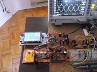
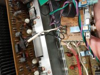
I've got a Marantz Pm400 on my bench, nice amplifier. It works, one channel playing fine, the other has weird noise which almost gets dangerous to speakers - it's something like a cracking/almost a bit like fireworks, sometimes gets lower, then suddenly comes back again, never stops. Still, that channel plays music with normal volume, too. No overheating, it's not a hum or buzz (it's volume independent), it's not the power supply (as said, other channel is fine). Changed most electrolytics in the defective channel, no difference. Decided to start isolating the problem, so I disconnected the power amp section from the pre amp section and grounded it's input. As expected, still the same noise problem in the defective channel, while other good channel now dead silent, as it should be. Grabbed my oscilloscope and started to trace the noise and also compare with the other good channel at some strategical points.

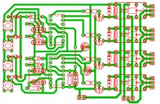
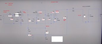
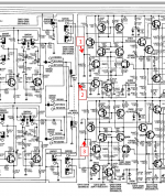
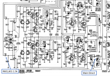
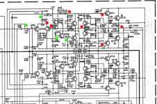
Below I add an excerpt of the schematic of the defective channel (power amp part), where I marked green dots on places where there was no noise present and red dots, where it was present. The noise looks like some random "spikes" around some millivolts, quite intense, of varying frequency and amplitude, it's not white noise or something. It's more a crackling.
From what I understand, after doing some research, this will probably be caused by some transistor in one of the stages of the power amp which is failing and developed this noise, right? If it was a resistor or a capacitor, would be more like white noise and more consistent, lower amplitude, no?
Also, doesn't seem to be a broken solder joint or intermittent "short circuit", as I tapped around that section with a wooden tool quite thoroughly and nothing really changed.
Haven't done the freeze spray trick yet.

Now I'm reaching out to you guys, as I don't understand very well the design of the output stage, it's a little complex, I know the first stage is the diff amp and I know what the last stage does, obviously, but can't identify well the rest (don't know where the VAS is, for example), so not sure if maybe with some help understanding the circuit better, finding the culprit would be easier?

As you can see from the red dots, I'm pretty sure the noise appears somewhere after the stage of Q707 and Q709, as it is not present at the base of Q705 nor Q707, but is present at base of Q713 and Q711. It's also not present at the common point for differential stage (at Zener), but it is present directly at emitter of inverting diff amp transistor and its base, which is where the feedback arrives from the output power transistors (which obviously carries the noise), which is also why it is present at the emitters of QN01 and QN03. Am I thinking correctly here? Or could the noise go the other way round, could it be the output transistors and the feedback connection injects the noise signal in the whole circuit over inverting input of diff amp stage?

What would be best to do next? Please, some opinions on this.

a) Apply freeze spray (I only have a non-invertible compressed air can, I hope it does the job) to the transistors which are suspects, to see if something changes

b) Disconnect R723 and 725 (output transistor resistors), so that no feedback goes to inverting input of diff amp and see if that changes noise? Or would that make the amp instable or other problems during this brief testing?

c) Disconnect R709 (resistor to base of inverting diff amp transistor) Q703, so that feedback doesn't get there and start isolating this way one transistor after the other, working from left to right, interrupting signal temporarily to test?

d) is it possible to measure (in terms of voltage, ohms or current) a transistor which has developed this kind of noise problems? or, as it is still partially working (it stil puts the music through), measurements would all be normal?

e) lastly, should I simply start substituting transistors in pairs, if necessary, starting with Q709 and Q707, then QN01 and 03, then Q703, hoping to eliminate the problem by luck, so not to loose much time in tracing it? this is a paid task, but not per hour, obviously.


Thanks in advance. And sorry for low quality of schematic, it's the only service manual I can find.

Attachments

  • pm400_noise in channel.png
    pm400_noise in channel.png
    432.4 KB · Views: 263

[Free] Parts for Zaphaudio ZBM4 bookshelf speaker build

Hi folks,

I never got around to building this one. Time to pass the parts on to someone who will.

Includes speaker drivers and crossover components.

Full plans available at:

Zaph|Audio - 4" Bargain Mini

Free, just pick up or pay shipping from Brooklyn, NY.


From MCM:
2 x MCM 55-1853 4" Shielded Aluminum Cone Woofer

From Madisound:
2 x Aurasound NT1-204-8D 3/4" Titanium Dome Tweeter (NT1-204-8D)
2 x Bennic Poly 2.7 mfd (BP2.7)
2 x Bennic Poly 10 mfd (BP10)
2 x Bennic Poly 3.3 mfd (BP3.3)
2 x Madisound 1.5 mH 19 AWG Air Core Inductor (1.5MHL)
2 x Madisound 0.25 mH 19 AWG Air Core Inductor (.25MHL)
2 x Eagle 5 ohms (5E)
2 x Mundorf 3.9 ohm Metal Oxide Film Resistors (MOX3.9)

(For reference, parts were ~$120 in 2010)

Attachments

  • IMG_3095.jpg
    IMG_3095.jpg
    711.3 KB · Views: 228
  • IMG_3094.jpg
    IMG_3094.jpg
    854.9 KB · Views: 228

anyone here use PRV's 2" phenolic or Ti drivers ?

just wondering. PRV specs their phenolic 2" format drivers with that tiny round horn which makes it difficult for me to understand how they might perform with larger horn.

my intent is home use and application could vary from a K-tube up to Klipsch K280 horn.

Voice Coil's Test Bench review of D4400Tl-ND looked scary in one graph with a 20dB hole around 9KHz.

any experiences/impressions of the 2" and 1.4" PRV compression drivers would be appreciated as would comparisons to Selenium.

I might just grab a Timpano 2" Ti as cheap experiment


which of these if any would work to 500 on a larger horn? Only the 2 inch coil small magnet D2200Ph is rated to 500Hz.

OyaLEGf.jpg

Toroid Transformer Winding

I've been goofing around with an amp design for a while now and am attempting to come up with a power supply that will use parts that I have on hand. I have several large toroidal isolation transformers that I have been wanting to use, but 120v isn't overtly useful here. I'm going to be using 6GC5's for the output, and they are happy at that voltage, but I want to use 6DJ8's in cascode on the front end, and I need at least 180v for those. A little more would probably be ideal. I was considering using a doubler to get that higher voltage, but I thought it might be neat to extend the secondary on one of those toroids to get whatever voltage I need. There is plenty of room for extra windings, and they ran at close to 10A steady-state in the equipment that I pulled them from. I thought maybe I could use the original "tap" on the secondary as the low voltage section and extend the winding to a new tap that would be the high voltage section. Then just have two bridge rectifiers, etc. I'd also have to add a filament winding. What I'd like to know is if that would introduce some sort of issue that I am not aware of. I could in theory wind a completely new winding for the high voltage, but that would be a lot more of a hassle. Possibly extend the original winding for the high voltage and then add a new winding for the low voltage. I'm not sure yet. If this goes well, I'd like to eventually use the rest of those toroids for other amp projects. Do any of you know of any problems I would encounter by doing this? If acceptable, I'm going to build enclosures for the toroids out of stainless steel sheet metal. I have a bunch of it on hand.

I've included a rough schematic to give a better idea of what I'm talking about. Voltages aren't exact here. It's just for illustration purposes.

Thank you for the help. I'd be lost without these forums.

Attachments

  • dual rectifier.JPG
    dual rectifier.JPG
    47.4 KB · Views: 265

Rockford Power P500-2

Working on a Power P500-2. The amp is going into protect on and off. No shorts in the output. Pulled the outputs anyway. The amp pulses in and out of protect. Power led and protect led flashing on and off. Anyone have the schematic on this model? It has been released but Rockford can't email schematics any more. You have to submit a question and wait for a response. I've done that but thought someone on here might already have it and I could get it quicker.

Attachments

  • 20210617_142340.jpg
    20210617_142340.jpg
    1 MB · Views: 116

Building my SqueezeNext

I have a bit of free time on my hands - guess I need to mess with the sound system...

Where I am today:
The living room system is a Squeezebox Touch connected via SPDIF/RCA to an external (1st generation Berkeley Audio Alpha) DAC. DAC is connected via balanced cables to ACA mono amps and DIY speakers. The rest of the house is a mix of Touch, Radio, Squeezebox3 and Raspberry Pi with Allo and HiFiBerry HATs - every Raspberry Pi, including the one acting as the LMS is running piCorePlayer.
To make things as easy as possible for my wife and I, the Touch is doing volume control (with the DAC volume control set to 100%) so that we only have to deal with a single remote, and we can manage everything through the Material skin and our home automation system.

While I've never verified this, it was my understanding that the Touch did volume manipulation with the least significant 8 bits - this was fine when all my music was 16-bit since SPDIF can pass 24-bits, but I now have a larger library of Hi-res music.

What I'm looking to do:
* Assemble a very high quality single box digital audio player and integrated DAC with volume control, including both RCA and balanced analog outputs. (My strong preference is for a DIY kit to round out my system and for the performance/cost ratio - I'm not like a number of you that are building your own boards. I'm also fine with assembling a number of existing boards and a touchscreen into a custom chassis.)
* Support for 192/24 files and, headroom for higher resolutions.
* It's got to have a high WAF factor - she won't let me stick a stack of boards in the living room.
* Squeezebox client for integration with existing whole-house LMS/Squeezebox system.
* DSP functionality - mostly to get loudness contour (ISO 226) control since a lot of this is lower volume listening.
* It's desirable but not required to include support for HDCD (haven't seen much of that) and MQA decoding.
* It's desirable but not required to include a nice color touchscreen since I think that's a nice touch.

Questions
* As I'm starting this investigation, appreciate any feedback or suggestions, additional requirements that I haven't considered, specific hardware and software suggestions, etc.
* Based on my research, I've been focusing on the Audiophonics Balanced DAC 2xES9038Q2M kit running Moode. Any feedback from those that have built this kit? Are their other high quality integrated player/DAC DIY kits that I should be considering? Has anyone used the DAC board and built this into a box with a high-quality color touchscreen while running Moode?
* Am I correct in assuming that 32-bit DACs with volume control such as the Audiophonics Balanced DAC 2xES9038Q2M will not strip data from 24-bit data files? My assumption is that the Raspberry Pi will pass unaltered 24-bit files to the DAC, and then the software on the Raspberry Pi will directly manipulate the DAC hardware to adjust the digital volume - is that correct? Or are the source files manipulated for volume before being sent out via I2S? I'm assuming that digital volume on the newest hardware will be an improvement compared to what is being done on the Touch.
* I was initially leaning towards an I2S connection, but is it better for me to consider USB between player and DAC, since that could also be 32-bit? I know that this opens up a whole new area of questions but have to ask.
* Any feedback on Moode in general? While all my other systems are running PCP, I'm looking at Moode due to the dsp integration, which includes a loudness contour.
* Does anyone know about DIY kits that integrate MQA decoding, such as the ES9068AS?

Thanks!

(I tried posting on the squeezebox forum but haven't received any feedback - cross-posting it here.)

Sub driver selection for best transient response

Hi all,

For selecting a subwoofer driver (12" to 18") what TS parameters define better transient response (fast attack or accuracy) ??

As far as I know, acceleration factor (BL/MMS) should be high. What other TSP or What points in published graphs to be checked ??

(Designing the cabinet for good transients is a different story. This question is only for selecting driver)

Thanks in advance
Audfrknaveen

Recommendation to build enclosure for Coral Beta 10

Greetings.
I have a pair of Coral beta 10. I have a problem with the decision to build BHL original enclosure or to try TQWT box or something on your recommendation
I would like to have good bass as possible, my room is 25m2 and speaker placement is close to the wall.

I am attaching the link of the TQWT case for beta 10 from the German forum.
which I would like try to do
I ask for your opinion and help.

Hifi-Selbstbau - Coral Beta 10B

Best regards.
Miha

Weight/mass on back of speaker

So playing with my new Burro Betsy fullrange to go into my OB I made an attachment, or holder, to hold the speakers onto the baffle. On this attachment I have som lead pieces and two smaller iron pieces, total of about 3kg. I figure the added mass on the back of the speaker makes for a more rigid fixture. I dunno, probably just a waste of time, but why not. I love creating much more to do than necessary.
But I am a bit surprised at how much the resonance shifted by this. It was 55Hz when the speaker was alone in free air. But mounted on the small baffle and with the 3kg of mass behind it, the resonance is at 119Hz and much lower in max value, ca 20ohm, down from ca 70ohms at 55Hz in free air.

This normal?

Attachments

  • betsyfreeair.png
    betsyfreeair.png
    54.6 KB · Views: 291
  • Betsyinattachment.png
    Betsyinattachment.png
    38.6 KB · Views: 302
  • 20210620_121736.jpg
    20210620_121736.jpg
    288.5 KB · Views: 272
  • 20210620_121802.jpg
    20210620_121802.jpg
    270.3 KB · Views: 273
  • 20210619_151705.jpg
    20210619_151705.jpg
    211.6 KB · Views: 323
  • 20210621_000237.jpg
    20210621_000237.jpg
    340 KB · Views: 173
  • 20210621_000247.jpg
    20210621_000247.jpg
    304.7 KB · Views: 142
  • 20210620_111315.jpg
    20210620_111315.jpg
    257 KB · Views: 137
  • 20210620_201414.jpg
    20210620_201414.jpg
    284.7 KB · Views: 149

Is there a way to turn a near-field suf-woofer into a far field subwoofer?

This is in reference to the issue mentioned on this link: No bass or out-of-phase bass, midrange and treble after swapping amplifier.


The sub-woofer I have modded seems to have very little bass, the manufacturer didn't say it explicitly that it has to be placed between the satellites but suggested that we keep it on the desk and many other consumers also reported better bass response with it on the desk. There is no space for it on the desk, is there a way I can turn it into a far field sub-woofer? It's enclosure is made with MDF, I think.

Free NOS Acutex 415 STR cartridge in Holland

Dear audio friends,
I need your help.
I am looking for a room or an apartment to rent for my daughter who will be attending the University of Leiden in The Hague from next September.
From Italy it is very difficult to find a satisfactory accommodation so I decided to give this new cartridge to someone who will give me concrete help.
I thank you and I trust in your help.
Regards
Guglielmo

Attachments

  • Acutex.jpg
    Acutex.jpg
    110.9 KB · Views: 279
Projects by fanatics, for fanatics
Get answers and advice for everyone wanting to learn the art of audio.
Join the Community
507,708
Members
7,885,325
Messages

Filter

Forum Statistics

Threads
406,091
Messages
7,885,325
Members
507,708
Latest member
ahmadmusowwir