You are using an out of date browser. It may not display this or other websites correctly.
You should upgrade or use an alternative browser.
You should upgrade or use an alternative browser.
Filters
Show only:
Broken EMU0204
- By paolopenna
- Equipment & Tools
- 3 Replies
Hello fine people,
I am, well, I was a lucky owner of an EMU0204 USB sound interface.
I used that to make many measurements with Spectralab, Arta and recently MultiInstruments.
That Interface WAS great.
One of these evening I found myself using a wrong USB-HUB power supply with 12V instead of 5V. The board of the 0204 broken up with a roasted plastic smell.
Does someone on the net knows where to find schematics or any useful stuff to try and repair the board?
I 'd apreciate any kind of help with this issue.
Thank You all.
Paolo.
Pair of large Community Biradial PA theatre speaker horns
- Swap Meet
- 0 Replies
$500AUD, Selling a pair of horns with the mouth extended by me with plywood. Wife/GF acceptance factor is zero so willing to sell these at the right price, if not I'll just keep them in the garage.
Pickup from Sydney region, Australia, only.
My workmanship isn't the best but I don't care if it did the job. If you don't want the wood extensions, they can be unscrewed from the fiberglass horns.
Dont know what the nominal dispersion angles are or the precise model of these horns.
The original fiberglass community horns measures 75x30x35cm W H D
With the mouth extension, the horns measure approx 90x55x55cm
2" exit
Can come with B&C dcm50 compression drivers at an extra cost.
Hello from Singapore
- By toydestroyer
- Introductions
- 6 Replies
Doing the obligatory hello post.
Been playing around with the idea of building my own amps for a long time and now that we can't travel for work it seems like an ideal time to scratch that itch. Understanding schematics and why certain things go where still hurts my brain a little. Hoping by building a few easier projects that it all starts to click together.
First project might be a Elekit. More of a soldering project that DIY but it seems like they're decent enough and not such a minefield like the random Chinese kits on eBay. Over time I'd like to build something with tubes and transistors similar to the Copland CSA 100 (I understand my home projects are unlikely to sound as good as a properly developed mega bucks product, but that's no fun).
Topping D90 SE with Virtins
- By littlestevie
- Software Tools
- 0 Replies
Hello all,
Came across the review of the Topping D90SE - Topping D90SE Review (Balanced DAC) | Audio Science Review (ASR) Forum
Was wondering if it is possible to pair it with Virtins or AP Flex software to use it as a measurement tool?
The DAC performance is quite astonishing. Thinking that it would make a great generator?
Any views?
Thanks!
Looking for FRD ZMA files for the D2608/91300
Looking for FRD & ZMA files for the D2608/91300
Hi
Maybe someone has FRD and ZMA files for the D2608/91300?
I would really appreciate it.
Hi
Maybe someone has FRD and ZMA files for the D2608/91300?
I would really appreciate it.
NAD C352 Protect mode
- By Lynyrd
- Solid State
- 184 Replies
Hello.
Integrated amplifier NAD C352.
In Protect mode.
All 4 fuses are OK
Where I need control please.
SM
NAD C 352 Service Manual
Integrated amplifier NAD C352.
In Protect mode.
All 4 fuses are OK
Where I need control please.
SM
NAD C 352 Service Manual
Connecting a turntable to a TV
- By affa44
- Everything Else
- 6 Replies
Hi,
I have looked through recommended threads to no avail.
I'm not sure where to post my query.
A few years ago I purchased a Sherwood PM-9805 turntable and have never used it.
At the time I purchased a DOSS PA005 pre-amplifier.
I don’t have any audio systems now, and want to play records through my Kogan TV, model KALED40XXXTA-A.
I have connected the turntable cables to the pre-amp (there is a ground wire but no position on the pre-amp to connect it to), and then used an RCA cable to connect to the L/R audio inputs on the TV.
There is no sound.
I don’t know if the problem is the turntable, the pre-amp or the TV.
Is it critical to connect the earth wire? If so, how?
How can I test the pre-amp?
Does anyone have suggestions?
I'm not an audio expert. 😕
Regards
4:15 PM
To:counts
PS Completed Pass DIY B1 board + Alps Blue 20k stereo
- By Paddy Garcia
- Swap Meet
- 1 Replies
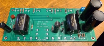
Great preamp but I upgraded to a B1K + Muses volume control so these are surplus to my needs:
The Pass DIY B1 was built from Mr Pass's store kit including matched JFETS, with Jatzen MKP caps in the audio path. The Alps blue 20k stereo pot is quiet.
$85 delivered in the US, $100 for Europe and most of the rest of the world.
The Pass DIY B1 was built from Mr Pass's store kit including matched JFETS, with Jatzen MKP caps in the audio path. The Alps blue 20k stereo pot is quiet.
$85 delivered in the US, $100 for Europe and most of the rest of the world.
Attachments
Novo Headphone Amp Kit
- By PeterV98
- Headphone Systems
- 24 Replies
Has anyone built this Headphone Amp kit from Graham Slee. The Novo.
DAK Novo Headphone Amplifier Kit - HiFi System Components
DAK Novo Headphone Amplifier Kit - HiFi System Components
HP333A to spectrum analyser impedance mismatch
- Equipment & Tools
- 13 Replies
Hi All,
I've just obtained one of these old distortion analysers and it works incredibly well for something built in the 70s and quite probably unserviced since then.
I've managed to get some sensible measurements from it and am following the "Greening of an IG-18" along with it quite nicely.
It has an output which i am plugging into scope at the moment for some basic FFT but would like to pipe it into a Tek 2712 spectrum analyser I have for high frequency work.
The issue is that the output would like to see a 600ohm load and the spectrum analyser has a 50 ohm input resulting a collapse of the voltage level of the signal from the HP to a point where it looks very noisy and ugly on the scope.
Being a noob at all of this I'm not sure what i need to correct the mismatch, I'm guessing some sort of active buffer amplifier and am thinking this might be a good place to put some of the filters that the HP lacks, chiefly a LP filter.
I'd like to have a stab at a DIY product if at all possible, but if something cheap, easy and high performance is out there I would consider it too.
How to wire input transformers
- By itsikhefez
- Tubes / Valves
- 3 Replies
Hi,
I've got 2 pairs of input transformers which I'd like to use for some upcoming projects (Baby Huey EL84, Tubelab TSE)
I need some help with wiring and mounting for unbalanced input, into an unbalanced circuit.
They are:
- Hammond 140UEX (https://www.hammfg.com/files/parts/pdf/140UEX.pdf)
- Jensen JT-11P-1
To my understanding, the case on the Hammond is the same as the white wire on the Jensen.
I understand that I should change the input resistors on the PCB to 10K to give the proper load resistance to the transformer.
Taking the 140UEX for example, the wiring seems straight-forward, RED-YEL to the RCA jack, and GRN-BLU to the PCB input terminal.
However, I am not sure if the transformer chassis needs to be isolated from the amp chassis, and where to tie the star-ground of the PCB (directly to chassis as without the transformer or otherwise?)
The Jensen introduces 2 extra wires (white and black) which are related to the above questions.
Thanks
Piezo PU- 402 Syntec S-220 Tone Arm recommended cartridge
- By avelasco
- Analogue Source
- 2 Replies
Hi
I'm starting a new project, I want to make a turntable controlled by a microcontroller and I just bought a tonearm from eBay is a Piezo PU- 402 Syntec S-220
Could you please recommend me one or tell me the cartridge that you are using with it?
I know that your taste is different from mine, I only want to know the difference options that I have
Piezo PU- 402 Syntec S-220 Tone Arm | eBay

Thermal isolation of electrolytic capacitors in tube amplifiers
- By VladBath
- Tubes / Valves
- 24 Replies
Hello, all!
I am not a very good searcher - I couldn't find any info on the subject of my request, which is - thermal isolation of electrolytic capacitors in tube amplifiers.
The problem is obvious - the higher the operating temperature, the lower the life of electrolytic capacitors, and many tube amplifiers have el. capacitors very near the tubes. The whole amplifier runs quite hot, and the caps much more so, being close to the tubes.
Currently, I found a new favorite amplifier which I very much enjoy, and its two main V+ caps are exposed on the top plate few cm from the tubes.
They are too big to substitute for a film cap (330uF/450V each). In future, I may try substituting them for AN Kaisei for better sonics, but it will not alleviate the overheating problem.
I think of something like aluminum or steel cylindrical covers for the caps, lined on the inside with some heat-isolating material, and maybe even placing a small radiator on top of each cap.
What do you think, is it idiocy that may even worsen the things (caps slowly cooking inside the thermal isolation), or is it more or less sound? Also, maybe such devices already exist, and I just don't know?
Please, share your wisdom
Best regards,
Vlad
snubber circuit best place
- By goodguys
- Power Supplies
- 11 Replies
Hi thanks for reading. A lot of people use a capacitor and resistor across a transformer to snub and reduce spikes from the power supply. But is this the best place to put the snubbing circuit.
What about placing it after the rectifer, so it snubs the transformer and rectifier. Or is better to place it after the big power supply capacitors, or any benefit to leaving it out of the power supply and placing the snubber on each of the amp boards.
Which is the best place to put the snubbing circuit to get the lowest noise.
And is there any benefit to using more than one snubbing circuit to possibly get lower noise..
Thanks
FS: PureDSD DSC2
For sale DSC2 DAC
www.puredsd.ru
This is the configuration implemented :
- NXP 74ahct595D shift-registers
- Vishays's PAT 4.99k tantalum-nitride resistor
- Dual NDK oscillators (NZ2520SDA / 49.152Mhz + 44.1584Mhz)
- "Chinese" Black OTP 300+300ohm
- Beaglebone Green with firmware
full functionality and perfectly running.
Asking 350eur plus pp fee plus postage...
Shipped internationally. THX
 [/IMG]
 [/IMG]
www.puredsd.ru
This is the configuration implemented :
- NXP 74ahct595D shift-registers
- Vishays's PAT 4.99k tantalum-nitride resistor
- Dual NDK oscillators (NZ2520SDA / 49.152Mhz + 44.1584Mhz)
- "Chinese" Black OTP 300+300ohm
- Beaglebone Green with firmware
full functionality and perfectly running.
Asking 350eur plus pp fee plus postage...
Shipped internationally. THX
Biasing Class AB amps vs Class A/High Bias AB amps
- By qguy2000
- Solid State
- 1 Replies
I have bias a couple of vintage amps/receivers and basically relied on the service manual to bias the amp, basically I measure the current between two test points and set the bias at a certain current as recommended by the manufacturer, wait 10-15 minutes and check if the current has drifted and adjust accordingly. Recently I acquired a Usher R1.5 power amp, it is a high bias amp, delivering 50 watts Class A and 150 at Class AB. No service manual was available, searching the net, I got a lot of recommendations to bias the amp until the heatsinks gets a temperature of 50c after idling for an hour. Apparently this is the recommended setting for Class A and high bias amps. Is there recommended heatsink temperate for Class AB amps?
New subwoofer crackling at higher volume
- By RIVATI
- Subwoofers
- 9 Replies
Hi,
I hope "crackling" is the right word, I just got a new subwoofer:
SB Acoustics SB20PFC30-4
Which has RMS 50W and Max 100W at 4ohms
SB Acoustics SB20PFC30 - 8" Woofer
I connected it to my amplifier, the Arylic Up2stream 2.1 amp:
2.1 Amplifier with 100W+50W *2 for DIY Audio-Arylic.com
– arylic
Which has power output of:
2x50W@4Ω + 100W@2Ω BTL load at 24V
2x30W@8Ω + 75W@4Ω BTL load at 24V
2x22W@8Ω + 48W@4Ω BTL load at 19V
2x15W@8Ω + 30W@4Ω m BLT load at 15V
The amplifier is powered by a battery board which outputs 21V:
Dayton Audio - LBB-5S 18650 5-24V Input 21V Lithium Battery Board with Balance/Charge Protection
I've read that having a speaker which has more wattage than the amplifier can output, can cause clipping at higher volumes.
I thought that I was safe with this combination but when I have the amplifier at a higher volume (around 70%) I hear a crackling noise coming from the subwoofer.
What could this be? Is my combination of all these parts not right (after I've researched for months trying to find the good combination 🙁 )
There is a bass-gain knob on the amplifier but I've reset it to 0, and checked the negative/positive wires on both the subwoofer and amplifier.
PS. Currently breaking in the subwoofer (not at a high volume), don't know if that should fix the issue.
Also maybe important to say, I only have the subwoofer connected right now, the 2 channels are not connected.
Thanks in advance.
What are ideal dimensions for 5" driver sealed enclosure?
- Subwoofers
- 13 Replies
I want to make a sealed sub-woofer, the driver size I have in spare is a 5" driver. What should be the dimensions of the sealed enclosure?
DIY replacement for a velodyne dd10?
- By Leffler
- Subwoofers
- 9 Replies
I have a pretty good system going, high end aspirations, rooted in measuring and real world budget prioritisation.
My main speakers are DIY accuton 1" tweeters and accuton 7" woofers in a "stand mount", 11l enclosure. I originally intended them as satellites not to play bass and integrate with my dd10, but they sound really good on their own, just without that extra airiness that really low bass (sub 25hz) gives.
My DD10 went out though, second time, and I'm inclined to replace it with a DIY solution.
I have pretty high WAF requirements, besides that the idea is to cut the mains at 60 hz or so, and dsp for eq and room correction in the lowest end - and I am aiming for 20hz output at 90 db or so at least. My room is not very big.
I have a minidsp, a umik, and a pair of mcintosh mc7100 amps (2x100w / 1x300 watts into 8 ohm) to drive the sub/subs with. Bridged, those amps are min 8 ohms however, so I'll try to avoid 4 ohm drivers unless I want to stay at 100w (which should be quite sufficient I guess, I am not aiming for 110db output...)
---
Enough scope definition. I have been considering a few options. Budget would preferably be under $250 for the driver/ drivers - I think. Less would be nice, without too much compromise on performance.
* 8" woofers, either corner placed or "Watt / Puppy" speaker stand style. There is a pair of used Scan Speak 8" revelator 22W8851T00 for sale locally, I am tempted to try them, but it might seem a little wasteful to use for only sub 60hz, and a pair of 8"ers should probably not push enough air. However, I have tried this - I have a JBL GTO 804 (8" woofer for car use, that I used in my go-to-work car before Covid) in an 8 liter closed box that I have tried, and it works quite well - with extremely punishing bass tracks it distorts before it is quite loud enough but two 8" could maaaybe be enough? The Watt/ Puppy is 4x8"...
* 10" woofer, closed and Linkwitz transformed?
* 12" woofer would clearly be preferred but will probably end up too large... otherwise the Scan-Speak 30W/4558T00 seems to be the most common choice.
Thoughts?
Class D amp - battery as PSU
Hi All
I've recently undertook a project of building my first amp.
I plan on using the AA-AB32191 2 x 300w Class D amp.
Looking over the specs this will need 52v @ 16amp.
This is quite a lot of oomph and finding a PSU that supplies this kind of power is proving expensive (more than the amp itself).
So this has forced me to consider other options - one being to build a 14s2p lipo battery using 18650 lipo cells.
This would supply more than enough oomph.
The problem is now how much do I need to worry about keeping those cells charged?
I plan on using a cheap lipo charging circuit to keep them topped up.
Due to the way an amp plays music, ie, it's really only the occasional full volume bass that will push the amp and PSU to the max, I'm thinking I don't need the full 16amp current to keep the batteries topped up?
I'm curious if anyone has created a PSU out of lipos, and if so, any gotchas?
JamJar: an HPA-1-inspired power amp
Based on the success of my HPA-1 clone, I've been playing with a sim of an HPA-1-esque topology with 3 pairs of laterals for the output stage.
It's designed to go into a case built around @mbrennwa's Aleph-style heatsinks. I'm thinking those should be good for at least 0.17ºC/W (with 2 for each channel).
Any thoughts appreciated.
Cheers,
Jeff.
It's designed to go into a case built around @mbrennwa's Aleph-style heatsinks. I'm thinking those should be good for at least 0.17ºC/W (with 2 for each channel).
Any thoughts appreciated.
Cheers,
Jeff.
Attachments
An interesting paper on bracing lightweight cabinets
perhaps this paper has been discussed before - if so, please remove. If not then it may be useful for some pro and boombox reflex / sealed cabinets. (folded horn tend to self brace and 15mm plywood can be sufficient)
.
https://core.ac.uk/download/pdf/84005542.pdf
.
https://core.ac.uk/download/pdf/84005542.pdf
How to get I2S from SAA7210.
- By vadimgal
- Digital Source
- 1 Replies
Hello,
Cam somebody tel me please:
How to get I2S ( BCK,LRCK,MCLK, DATA) from Philips SAA7210 which is installing in my transport. Planning to feed Drirectsatream DAC via I2S.
Thanks.
Cam somebody tel me please:
How to get I2S ( BCK,LRCK,MCLK, DATA) from Philips SAA7210 which is installing in my transport. Planning to feed Drirectsatream DAC via I2S.
Thanks.
transistor seller wanted
- By robertor
- Solid State
- 18 Replies
Hello everybody.
I'm looking for the following transistors (to try to repair 2 Yamaha amplifiers):
2SD845 + 2SB755 (Yamaha A-760);
2SA663 + 2SC793 or 2SA745 + 2SC1403 (Yamaha Ca-610).
Can you recommend one or more "reliable" sellers where to buy them?
On ebay, aliexpress etc etc there are many fake branded Toshiba and Sanken, for this reason I ask the experts for advice.
Thanks in advance for any suggestions ...
Rob
One Tweeter Failing -
- By andorjkiss
- Multi-Way
- 4 Replies
Hi,
I have one tweeter (left) that consistently fails at loud volume. The right never does. The tweeter is this one (Peerless by Tymphany D19TD-05 3/4" Poly Dome Tweeter), and the speakers are PSB300s, running from a DENON AVR-900 (100 W per channel). Source for the failure is usually the turntable (THORENS TD 150 MKII A/B - rebuilt by me). But it does happen with the DENON CD deck. Speaker wire is vanilla WalMart Phillips 18 G braieded copper speaker wire. One thing that I did do (before I knew not to do it) was that I cut the right speaker wire shorter than the left to prevent excessive coiling of the right spk wire; amp is on the right hand side of the room.
Question: Is the differential in the speaker wire to blame, or is it that I've got the amp cranked up too high (max) for the speakers?
The rating on the speakers is "Rated for 10-80 Watts at 6 Ohms Impedance."
Thanks.
Modding the Darkvoice 336se OTL headphone amp
- By KHashmi316
- Tubes / Valves
- 9 Replies


FYI, the Darkvoice 336se is a popular tube headphone amp from China. It can roughly be compared to Bottlehead Crack, the latter being better built and pricier. I have not made such comparisons, however.
A few mods have been suggested for the 336se.
I did the Preamp Output ground (remove) mod. I think that made a positive improvement.
Next, I did the LED mod (replacing the 1k R). I used std. red LEDs. Not sure about the results. This may have worsened the sound???? Not sure!
Have there been comments on the brand or type of LED to use? I've heard that color can make a diff. (because diff. colors have different doping materials and diff. current requirements).
Other than tube rolling -- unless you know of any real juicy tubes to install -- suggest whatever comes to mind for further improvement of stock unit.
References:
Darkvoice and Crack Mods | Super Best Audio Friends
Massdrop--thread on 336se
Darkvoice 336i & 336SE Tuberolling PartII | Page 65 | Headphone Reviews and Discussion - Head-Fi.org
Two 3255: Ground Loop Across 3e DSP Outputs
- Class D
- 7 Replies
Hello,
The dsp is connected to two TPA 3255 amps with unbalanced inputs.
First question, I connected AGND and + on the DSP outputs to, - and + of amp inputs, respectively, is this correct?
Both amps are powered by the same power supply, which only has a positive and negative lead. I have a ground loop between the negative terminal of both amps and across the outputs of the dsp (I get ground noise even when one of the amps is only connected to negative power in and even when the dsp is not powered on but with its outputs connected to the amps).
How should I break this ground loop across the DSP's balanced outputs?
Thanks!
boostered opamp audio amplifier
- Solid State
- 10 Replies
I have designed a boostered opamp audio amplifier based on AD820 and TIP125, TIP120.

The output stage is controlled by the currents through the Vcc and Vee power rails by use of the resistors R4 and R5. The bias current through the output transistors is set by an adjustable current source LM334 and the fine trimmer R8 (10 Ohm). The output stage is in common emitter configuration. In this way the amplifier can operate with rail-to-rail output voltage swing.

What do you think about this circuit?
An externally hosted image should be here but it was not working when we last tested it.
The output stage is controlled by the currents through the Vcc and Vee power rails by use of the resistors R4 and R5. The bias current through the output transistors is set by an adjustable current source LM334 and the fine trimmer R8 (10 Ohm). The output stage is in common emitter configuration. In this way the amplifier can operate with rail-to-rail output voltage swing.
An externally hosted image should be here but it was not working when we last tested it.
What do you think about this circuit?
My new project: GaN amp and LLC+SinchroRec PSU
My new project: GaN amp and LLC+SinchroRec PSU
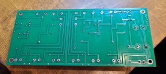
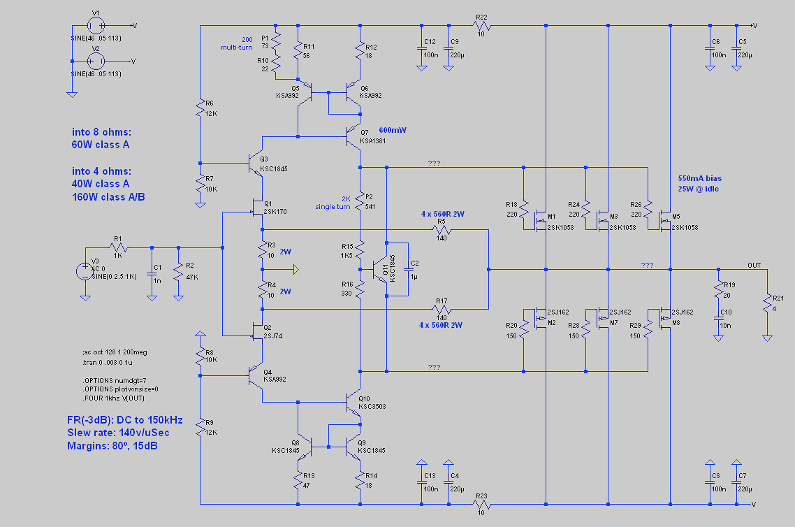
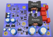
Amp have full differential structure
Amp- 400 4 ohm, 200 8 ohm nominal power, 600 and 300 maximum power.
Amp have overload, overtemperature protections.
With my PSU have DC protection.
PSU LLC and sincrorectifier.
Amp have full differential structure
Amp- 400 4 ohm, 200 8 ohm nominal power, 600 and 300 maximum power.
Amp have overload, overtemperature protections.
With my PSU have DC protection.
PSU LLC and sincrorectifier.
Attachments
3D printed enclosure plans - a work in progress
Recently I was going through all of my drivers that I bought years ago and didn't do anything with, and I decided that I should start a new project. Since I'm working from home most days, and spending a huge amount of time in front of a PC, I decided that I'll use some of these smaller drivers to build new desktop monitors. I thought it would be fun to utilize my 3D printer for this project, so I whipped up a design in Fusion 360. This design is a very blatant ripoff of the Sonus Faber Cremona design. That's one of my favorite commercial speakers, and until I can make a full size set, I thought it would be great to have a mini set! The drivers that I intend to use will be the Dayton ND105-4 midwoofer and the ND20FB-4 tweeter.
Here is the design so far:


Right now the enclosures are very basic, and not printable on my printer due to a limited print volume. I intend to build the cabinet walls from laminations that will bolt & glue together. The rear panel may also be made that way. I still need to design the laminations and the interlocking features. I also intend to hollow the sides & back panel out so that I can fill them with sand to help damp them. The front panel I'm not real sure of yet. I'll probably need to print it in 2 pieces glue it together, so I'll need to fool with different ways to split it so that I get a good solid keyed glue joint.
Cosmetically, I intend to wrap the sides, top & bottom panels with a cherry vinyl that I have left over from a previous project. It looks pretty nice for being vinyl, and it'll allow me to wrap the radius around to the front baffle, which I wouldn't be able to easily do with real veneer. The front & rear panels will be a satin black. I may experiment with wrapping the front baffle in a faux leather similar to the real Sonus design if I get ambitious.
The enclosure is just a tad over .19cu-ft as it sits, with the expectation that port volume, crossover and drivers themselves will bring it down to around .17-.18cu-ft. That variation doesn't have much of any impact on the overall response. SPL is with 15w of input, which is right below the driver's xmax at around 80hz. The driver unloads below 50hz, but since I'll be sitting 2' from them, realistically I'll probably never get them close to xmax.

No idea what I'll do for a crossover yet. I may fool with modeling it in PCD, but I don't seem to have good luck getting realistic results using FRD/ZMA files even when I extract minimum phase, so I'll probably take in-box measurements and design the filter from that. Because of the smooth response of the drivers, I'm hoping to get away with something nice and simple, but we'll see.
Here is the design so far:
Right now the enclosures are very basic, and not printable on my printer due to a limited print volume. I intend to build the cabinet walls from laminations that will bolt & glue together. The rear panel may also be made that way. I still need to design the laminations and the interlocking features. I also intend to hollow the sides & back panel out so that I can fill them with sand to help damp them. The front panel I'm not real sure of yet. I'll probably need to print it in 2 pieces glue it together, so I'll need to fool with different ways to split it so that I get a good solid keyed glue joint.
Cosmetically, I intend to wrap the sides, top & bottom panels with a cherry vinyl that I have left over from a previous project. It looks pretty nice for being vinyl, and it'll allow me to wrap the radius around to the front baffle, which I wouldn't be able to easily do with real veneer. The front & rear panels will be a satin black. I may experiment with wrapping the front baffle in a faux leather similar to the real Sonus design if I get ambitious.
The enclosure is just a tad over .19cu-ft as it sits, with the expectation that port volume, crossover and drivers themselves will bring it down to around .17-.18cu-ft. That variation doesn't have much of any impact on the overall response. SPL is with 15w of input, which is right below the driver's xmax at around 80hz. The driver unloads below 50hz, but since I'll be sitting 2' from them, realistically I'll probably never get them close to xmax.
No idea what I'll do for a crossover yet. I may fool with modeling it in PCD, but I don't seem to have good luck getting realistic results using FRD/ZMA files even when I extract minimum phase, so I'll probably take in-box measurements and design the filter from that. Because of the smooth response of the drivers, I'm hoping to get away with something nice and simple, but we'll see.
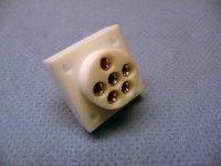
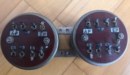
WTB: Stax normal bias 6-pin TEFLON socket
Hello,
I am looking for a Stax normal bias 6-pin TEFLON socket.
Please send me a message if you have an offer.
Thank you
I am looking for a Stax normal bias 6-pin TEFLON socket.
Please send me a message if you have an offer.
Thank you
Attachments
Sonus Faber Cremona HYBRID Clone
Hello everybody in a sunny and shiny day from Spain:
Introducing myself (already done in the appropriate forum) I’m Alberto, a 40 years old Guy who, not knowing almost nothing in the Speaker’s DIY world, has started his own project after 2 years willing to do it.
My aim is to clone the Sonus Faber Cremona Speakers but with a very low budget… let me explain:
I’ve been a long time crazy for the Cremona’s, but no way to buy them even in the used market, so thanks to one of my friends, I bought a used pair of Monitor Audio Gold Reference GR60 floorstanding speakers, that I have to say they sounds me like angels singing….
Monitor Audio Gold Reference 60 Floorstanding Speakers reviews - Audioreview.com
Speaker Asylum: REVIEW: Monitor Audio GR 60 Speakers by O'Shag
http://www.htguide.com/forum/showthr...-B-amp-W-804-S
A Review of the Perfect Loudspeaker: Monitor Audio Gold Reference 10 - Archived Threads 2001-2004 - Home Theater Forum
But I don’t like how they look all:
So, with my tight budget I thought I colud use the drivers and Xover from the GR60’s inside my cremona’s enclosure. After some tests and looking for lots of information I decided I would do something like this: my Hybrid Cremona’s:
And… the fact is that I designed from the beginning all the CAD drawings and everything and sent the drawings to a Computer cutting and milling, because the guys who had built the Cremona’s Clone in Spain constructed them by adding lots of layers to build the enclosure, but I was sure I wouldn’t be able to do like that and I thought it was easier, faster and much more safe to build them rib by rib, and the fact is that I was in the right way. I will add some pictures of building process later.
When I designed all the stuff I did with the following parameters:
Very similar volumes that the GR60’s but compatible volumes to the BIG_AL Cremona’s Clone… who knows if I will build with this drivers (that was my first opinion, but the budget is quite expensive for me)
I have already built the enclosure. It took me about 12 hours of gluing ribs from 5 to 5 and putting all the together to build the full enclosure (It took about 10 days leaving 24hours to dry each glued portion). This is the result (still not veneered):
And what happens now? Well, I have to say I’m really satisfied with the result and I’m very close to the starting point of this project long time ago: deciding whether or not to use my GR60’S drivers and Xover or a new drivers configuration, and here you are my options for you to give me your suggestions:
1.- Using the Cremona’s drivers and Xover (or the ones designed by my Spanish Friend) that is for each speaker: Morel Supreme Tweeter + Audiothecnology C-Quence 15 H 52 06 13 SD midrange + 2x Scanspeak 18W8531G00 woofers. All this stuff, Xover included and selling my GR60’s would be a $2100 investement (1550€). The pros is that this is a superb configuration, it sounds PERFECT and the Xover is already designed. The con is the hugh amount of money I don’t want to Spend.
2.- Build my own configuration accdording to my budget. For each speaker: Seas 27TDFC-H1189 Tweeter + SEAS MCA15RCY-H1262 mid + 2x SEAS U18RNX-H1571 woofers. All this stuff, adding a Behringer DCX2496 ultradrive pro Xover to avoid the passive Xover desing, and adding the mic and external sound card for measurement, all inclusive and selling my GR60’s would be a $410 investement (300€). The pros: no much expenses (I could rise my budget in drivers up to $675 or 500€). The cons: adding a new electronic device (The DCX2496) and lots of hours of measurement) and I don’t know the results… until I spend the money and test everything.
3.- Using the GR60’s stuff. The cheapest option, the worst looking but I’m pretty sure I will really have a good sound.
Do you think I will get more sound performance with options 1 or 2 or any other option you can suggest me?
I accept all your suggestions about drivers and Xovers, even if they are different to my ideas, but I need something tested and fully working and don’t want to test Xovers because I would become crazy for sure.
Thanks everybody for looking.
Introducing myself (already done in the appropriate forum) I’m Alberto, a 40 years old Guy who, not knowing almost nothing in the Speaker’s DIY world, has started his own project after 2 years willing to do it.
My aim is to clone the Sonus Faber Cremona Speakers but with a very low budget… let me explain:
I’ve been a long time crazy for the Cremona’s, but no way to buy them even in the used market, so thanks to one of my friends, I bought a used pair of Monitor Audio Gold Reference GR60 floorstanding speakers, that I have to say they sounds me like angels singing….
Monitor Audio Gold Reference 60 Floorstanding Speakers reviews - Audioreview.com
Speaker Asylum: REVIEW: Monitor Audio GR 60 Speakers by O'Shag
http://www.htguide.com/forum/showthr...-B-amp-W-804-S
A Review of the Perfect Loudspeaker: Monitor Audio Gold Reference 10 - Archived Threads 2001-2004 - Home Theater Forum
But I don’t like how they look all:
An externally hosted image should be here but it was not working when we last tested it.
So, with my tight budget I thought I colud use the drivers and Xover from the GR60’s inside my cremona’s enclosure. After some tests and looking for lots of information I decided I would do something like this: my Hybrid Cremona’s:
An externally hosted image should be here but it was not working when we last tested it.
And… the fact is that I designed from the beginning all the CAD drawings and everything and sent the drawings to a Computer cutting and milling, because the guys who had built the Cremona’s Clone in Spain constructed them by adding lots of layers to build the enclosure, but I was sure I wouldn’t be able to do like that and I thought it was easier, faster and much more safe to build them rib by rib, and the fact is that I was in the right way. I will add some pictures of building process later.
When I designed all the stuff I did with the following parameters:
Very similar volumes that the GR60’s but compatible volumes to the BIG_AL Cremona’s Clone… who knows if I will build with this drivers (that was my first opinion, but the budget is quite expensive for me)
An externally hosted image should be here but it was not working when we last tested it.
vs An externally hosted image should be here but it was not working when we last tested it.
I have already built the enclosure. It took me about 12 hours of gluing ribs from 5 to 5 and putting all the together to build the full enclosure (It took about 10 days leaving 24hours to dry each glued portion). This is the result (still not veneered):
An externally hosted image should be here but it was not working when we last tested it.
An externally hosted image should be here but it was not working when we last tested it.
And what happens now? Well, I have to say I’m really satisfied with the result and I’m very close to the starting point of this project long time ago: deciding whether or not to use my GR60’S drivers and Xover or a new drivers configuration, and here you are my options for you to give me your suggestions:
1.- Using the Cremona’s drivers and Xover (or the ones designed by my Spanish Friend) that is for each speaker: Morel Supreme Tweeter + Audiothecnology C-Quence 15 H 52 06 13 SD midrange + 2x Scanspeak 18W8531G00 woofers. All this stuff, Xover included and selling my GR60’s would be a $2100 investement (1550€). The pros is that this is a superb configuration, it sounds PERFECT and the Xover is already designed. The con is the hugh amount of money I don’t want to Spend.
2.- Build my own configuration accdording to my budget. For each speaker: Seas 27TDFC-H1189 Tweeter + SEAS MCA15RCY-H1262 mid + 2x SEAS U18RNX-H1571 woofers. All this stuff, adding a Behringer DCX2496 ultradrive pro Xover to avoid the passive Xover desing, and adding the mic and external sound card for measurement, all inclusive and selling my GR60’s would be a $410 investement (300€). The pros: no much expenses (I could rise my budget in drivers up to $675 or 500€). The cons: adding a new electronic device (The DCX2496) and lots of hours of measurement) and I don’t know the results… until I spend the money and test everything.
3.- Using the GR60’s stuff. The cheapest option, the worst looking but I’m pretty sure I will really have a good sound.
Do you think I will get more sound performance with options 1 or 2 or any other option you can suggest me?
I accept all your suggestions about drivers and Xovers, even if they are different to my ideas, but I need something tested and fully working and don’t want to test Xovers because I would become crazy for sure.
Thanks everybody for looking.
Love the 6n23p-ev
- By mdpaudio
- Tubes / Valves
- 3 Replies
I just threw the old 6n23p-ev in my Abdullah based KT130 SE amp and I’m loving the sound! It goes higher, lower, and more 3D than the 6922 and 6CG7 that I’ve tried before. I’ve got to order a few more just to have on hand. Anyone else like these tubes?
Frd and zma files for XSim.
- By santitrucco
- Software Tools
- 1 Replies
Hello everybody!
Someone could help me to make the files .frd or .zma or tell me what software could i make them with.
I need them to use with XSim to design a crossover.
Are from 18Sound HD1030 compression drivers.
Someone could help me to make the files .frd or .zma or tell me what software could i make them with.
I need them to use with XSim to design a crossover.
Are from 18Sound HD1030 compression drivers.
Attachments
Making mods to a Sony CDP-302
- By mjarve
- Digital Source
- 9 Replies
This may be asking for the moon, but what could I do to this old timer to perhaps make it a little better than it is. I have taken a pic of the inside if that helps. I'm fairly adept at modding analog stuff, but digital is unfamiliar territory for me. I might be beating a dead horse, but it just seems so well built compared to todays offerings I can't help but to try.
BTW: It works right now. I'm just looking for any tweaks/improvements I could make.
Thanks for any tips.
*Note: Picture is fairly large.
Sony CDP-302 internal pic.
BTW: It works right now. I'm just looking for any tweaks/improvements I could make.
Thanks for any tips.
*Note: Picture is fairly large.
Sony CDP-302 internal pic.
Tango Hirata XE60-3.5S for sale
Used pair of early Tango Hirata (not the ISO version) XE60-3.5s for sale. Great for most of the single-ended application eg.2a3, 300b etc. They are in beautiful physical condition and of course works as they should. However their factory boxes and papers are long gone.
I am asking USD1500, inclusive of shipping via EMS worldwide. PM me your email address to send pictures.
I am asking USD1500, inclusive of shipping via EMS worldwide. PM me your email address to send pictures.
Soldering difficult connectors
- By eriksquires
- Construction Tips
- 10 Replies
Hi All,
I have made a couple of DIY interconnects using inexpensive cable and KLH bullet, connectors. I think I managed to do OK with them but honestly the long term reliability worries me somewhat.
The RCA plugs use these tiny, flat connectors with U shaped prongs internally. They are flat, small, and have no hole to hook the wire through or around really. Looking at pictures online, the ones I had were definitely not curved and flat.
I'm just wondering, what is the soldering strategy of attaching a tiny wire to the end of a piece of metal when it barely has a place to put it, let alone tie it or put one inside the other?
Help to connect MALOTKI transfomers.
- By fuaelo
- Analog Line Level
- 58 Replies
Hi friends, im asking for help to connect two Malotki transformers to XLR in and out connectors to pass sound though them as a stereo pair. thanks in advance.
Please see attached picture.
Please see attached picture.
Attachments
Symmetrical amp clipping behavior - help needed
- By minek123
- Solid State
- 119 Replies
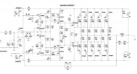
I have an amp design here, which evolved from non-symmetrical amps I already built in this thread.
So this is continuation, hopefully for the better.
See the attached LTSpice sim file, and screenshots (for 1kHz and 10kHz).
Everything seems to be working fine, except the clipping.
Looks kind of ugly.
Any help with improving clipping behavior (or anything else) in this amp would be appreciated.
Choice of transistors is determined by what I have (e.g. TTA/TTC, BD140, BC).
I simed it with different ones, to pretty much the same results. Also have higher voltage version with bigger fets,
but for this one I want to use IRF640/9640, as I have too many of them..
As it turns out, this thread evolved into "hands-on crash course in feedback stability", so keep reading if you want to
find out how to evaluate OLG, Bode plots, Phase Margin and Gain Margin.
For dummies.
Most recent schematic: post #69
Attachments
-
 wdrhld_baby_beast.comp.hexfet.10mar2021.jpg261.5 KB · Views: 653
 -
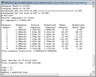 thd_1.png25.9 KB · Views: 721
 -
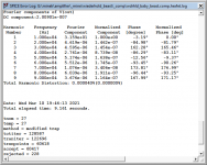 thd_10.png25.8 KB · Views: 632
 -
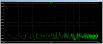 fft_1.png25.4 KB · Views: 611
 -
 fft_10.png25 KB · Views: 605
 -
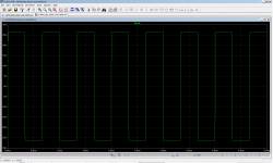 sqr1.png37.7 KB · Views: 259
 -
 sqr2.png39.1 KB · Views: 257
 -
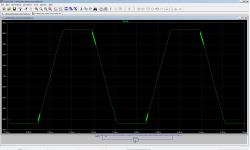 clip1.png39.9 KB · Views: 324
 -
wdrhld_baby_beast.comp.hexfet.10mar2021.asc17.4 KB · Views: 87
AudioXpress and Glass Audio Magazines
I'm thinning down my hard copy collection of magazines. AudioXpress from 2006-2008 with some older issues mixed in. Glass Audio random issues from the late 90s and early 2000s.
Ships via media post via USPS to your location.
Please PM if you are interested.

Ships via media post via USPS to your location.
Please PM if you are interested.
Help needed
Since the beginning of the pandemic I have had engineering parts and test equipment essentially dumped on me as companies changed and people moved on to new lives. If I were rational most would have left as e-waste, but I'm not and I'm sure there are others near me who could find utility for this excess stuff, but Its more than I can handle alone.
Is there anyone in the Bay Area interested in pawing through piles of caps, resistors, transistors, IC's, tubes etc. to sort into useful piles and help find homes for it all?
PM me if interested.
Is there anyone in the Bay Area interested in pawing through piles of caps, resistors, transistors, IC's, tubes etc. to sort into useful piles and help find homes for it all?
PM me if interested.
F7 clone kit and WHAMMY PCB
1) First Watt F7 amplifier clone kit containing all parts to build a working stereo amplifier (jfets, Semelab mofsets, resistors, pots), two pcbs (one for each channel) and a schematic. Nelson Pass has not released the official schematic for the F7, so this is a best-guess circuit that measures the same but may not be identical. Power supply, panel or hook up components are not included, just the parts to stuff the boards.
$160 USD plus shipping.
About the kit: this was purchased from a diyaudio member in 2020. He did the hard work of understanding the circuit, testing it, sourcing the parts, measuring transistors and pre-adjusting the pots. You can find information from him and other members who reverse engineered this circuit in the F7 thread. In addition to the kit, I will forward an email from him with additional details about his build. He bought and measured extra parts to get enough working components, and I was lucky enough to snag a set made from his excess stock. He tested components in a working circuit, so they are not factory sealed, but were not otherwise used by him or me. I never started construction. Unfortunately, running a COVID home school for my children ate all my free time for the past year and created a backlog of projects. Neither the designer nor I am making a profit: the kit is selling for the cost of the parts.
A few important details: I will share the schematic only with the buyer and only after purchase. The "long and skinny” PCBs require a longer chassis than the diyaudio deluxe and do not use the diyaudio universal heatsink drillings. You will need to source your own chassis and drill your own heatsinks. There is a silk screen error in one channel's PCB documented in the information I will give you. One of the most difficult parts of building the F7 is biasing the JFETS. This is done for you via prematched and preadjusted pots, which must go in the correct position according to the instructions. You still need to adjust the bias current by ear or with measurement, so this is not "plug and play", but much closer than if you sourced parts yourself.
2) WHAMMY headphone amplifier PCB. This is the PCB available in the diyaudio store. I have too many headphone amplifiers and will not build this one.
Save a few dollars at $20 plus shipping.
Shipping to the USA will be via USPS and is affordable. Shipping outside the USA can get quite expensive and be very slow these days.
CALRAD CR-12TX , Triaxial's (rebuilt)
Goodday for those of you who are looking for a good pair of CALRAD CR-12TX , 12" triaxle speakers that have been Re-built , yep new foam rool suspension, cones ahave been coated with PVA style coating and firmed up using carbon fiber ribs. Twweter horn flares are Aluminium and have been damped using, plumbers putty. Tweeter are mylar diaphrams (original). 20 Watss RMS powr handling and the coil DCR's are both around 7.4 ohms on each, Vas is unknown but likely in the 8 cu ft range.
Price is $165 for the pair. OBO
Shiiping from Calgary ALberta Canada Postal code is T3C2A1
Wieght is only around
An externally hosted image should be here but it was not working when we last tested it.
Price is $165 for the pair. OBO
Shiiping from Calgary ALberta Canada Postal code is T3C2A1
Wieght is only around
Hammond transformers available NOS
Hammond transformers 167P100's &167P36 NOS
I have 2 x Hammond # 167P100 , 100vac secondary , center tap , 5 amps.
and
One Hammond 167P36 , 36 VAC center tap , 180 va.
All are NOS never been used , good condition.
Asking $120 for pair of 167P100's
and $35 for 167P36
Shipping from Calgary Alberta Canada , postall code T3C2A1
Payment via e-trans in Canada , or cashiers cheque from us. Will provide complete details including tracking numbers fro UPS shipping to US. Canada Post in Canada unless otherwise specified !
Thanks Rich Allan
Repair service for Braun Regie 550
- By chap
- Solid State
- 1 Replies
Hi all.
OK. So here's the story.
1. I have 2 Braun Regie 550 receivers. I am a total sucker for these receivers, and I LOVE their performance and looks. I have the tape deck also, and now all I need is the turntable...ok that's another story.
2. One of them just decided to go into protection. Immediately upon turning on, the protection relay does not click, and of course, there is no sound at all now.
3. Before this, it was having a loud hum on all inputs. I replaced the filter caps (the big silver ones, or coupling caps?) in the power supply.
4. The hum went down a lot. But there was hum still in the phono -- engaging the phono stage gives a loud enough hum at just the 9o'clock position on volume. The hum increased with volume.
5. Very soon, the protection relay refused to click and the receiver has no sound at all.
6. The second Braun receiver has some loud scratchiness in the volume/bass/treble controls....Deoxited a couple of times. Still scratchy. Don't know if it needs anything more.
I am not very good at schematic reading, and would like to know if anyone wants to take on the project of fixing this, and doing a proper recapping of old caps.
** Schematic attached
** Service manual attached.
If anyone has ideas about possible issues I should look at, that is also something I am happy to try. Of course, I don't have any equipment to check amplifier bias and such.
Thanks for reading! Comments welcome!
Attachments
Sub woofer for Quad ESL 57s with active crossover
- By JMacI
- Planars & Exotics
- 19 Replies
I have a pair of stacked quads which I adore refurbished using Sheldon Stokes brilliant book. However my listening room is very large - about 10m x 8m with 4m ceiling so that the lower bass lacks ‘punch’.
I just picked up a pair of old but good B&W 801s and wondered about pursuing an active crossover set up with their enormous drivers.
Has anyone tried anything like that.?
I just picked up a pair of old but good B&W 801s and wondered about pursuing an active crossover set up with their enormous drivers.
Has anyone tried anything like that.?
Finally... Arrived SV-1616D
 https://flic.kr/p/2m9t2J7 by https://www.flickr.com/photos/64593884@N08/
WE300B X 2
Telefunken ECC82 X 2 Wrinkle Glass
Valvo 12AT7 VF3 B9A4", Made by Mullard, England, Blackburn Same Charge: "KHLC"
VALVO GZ34 Mullard

 https://flic.kr/p/2m9xLUo https://www.flickr.com/photos/64593884@N08/r
 https://flic.kr/p/2m9C1Ky https://www.flickr.com/photos/64593884@N08/
FS: DRA Labs MLSSA Acoustic test system with computer
Hello All,
I have a fully working MLSSA system that I'm selling. I have it listed here on eBay UK (hope eBay links are ok?)
DRA Laboratories MLSSA Acoustic Measurement System | eBay
Willing to sell only the card and installation disk if necessary as global shipping a PC is expensive!
I have a fully working MLSSA system that I'm selling. I have it listed here on eBay UK (hope eBay links are ok?)
DRA Laboratories MLSSA Acoustic Measurement System | eBay
Willing to sell only the card and installation disk if necessary as global shipping a PC is expensive!
Help assess Impulse Response of LXminis
Hello,
I started with using REW and UMIK-1 microphone to understand my room behaviour. On the way, I measured my LXminis. The Frequency Response is correct, but I'm puzzled with the Impulse Response measurement that does not looks at all like a pure dirac. See below:
- starts with a negative 100% (instead of expected positive),
- then a positive 80% (OK for a small "overshoot" but not that much).
Is this normal and related to the 2 drivers and the inverse polarity of the Full Range (by design inverse polarity to be in phase with the woofer at cross-over freq) ?
Is this abnormal and I should investigate ? In REW documentation, the picture for IR measurements shows a nice positive single peak, as expected, with only few ripples.
Nota, the Freq Response at crossover frequency is clean with no dip, which confirms that the woofer and the Full Range blend well and are in phase at that point.
This may be a quite stupid question, sorry for that. But willing to learn !
JMF
Attachments

Oscilloscope and high voltage
- By lim0nade
- Power Supplies
- 6 Replies
Hi guys.
I bought a pc based oscilloscope ISDS205A and now I study to use it.
I have a problem with a small standby pulse transformer, which of the primary coil should have < 300V.
In the user manual is said:
2, Oscilloscope with Probe: X1 CAN MEASURE -5V TO + 5V VOLTAGE, X10 CAN MEASURE -50V to + 50V.
3, The Measurement of the Electric Supply 220V / 110V IS DIFFERENT FROM THE NORMAL WAVEFORM MEASURMENT AND NEEDS TO BE RE-MEASURED BY AN ISOLATED TRANSFORMER.
Does that mean if i buy probe x100 I will be able to measure up to 500V ?
Sorry for the lame question,
I am learning now.
Cheers!
Newbie building subs with SB23MFCL45-8 drivers.
- By Bazabing
- Subwoofers
- 9 Replies
Hi Everyone
As the title suggests, I am completely new to building subs and wanted some advice on how to make this learning process as painless as possible!😀
I will try and keep this short but understand that most people here like a bit of background to help determine the best direction.
I should explain that I am currently constructing some floor standers, that started out as mini monitors (Gorens excellent Revelation mk2 www.audioexcite.com >> Revelation Two – Monitor MkII ). A house move and a bigger living room meant that 5.5" woofers just weren't enough! so they are being put into floor standers with 2 x 18w units each to beef up the low end. (active x-overs from 18w to 15w and Gorens passive x-over for the 15W to tweeter). I have built cabs with various panels that can be moved around or removed so I can play with different volumes and experiment with ported or sealed. Luckily I have a cousin who has built active speakers for some years now, helping me with this side of things (building the amps, measuring etc), but he has no experience with subs.
The reason why I am thinking of adding subs to this is because a bit more controlled low end is always a good thing 😀 and I already have 4 x SB23MFCL45-8 drive units (long story).
So now for the questions.....!
I am thinking that maybe a pair of sealed stereo subs, each with an up and down firing driver could be a good choice? (or not? - opinions please!)
Also what would be a good amp for this driver? The mains are going to be running some cheap but nice 125W modules that my cousin uses and rates highly, but I am not sure if this will provide enough grunt for subs?
I am also thinking that as LF tend to excite room modes more, maybe I should look at DSP to try and control this? (Mini DSP 2x4HD maybe?)
If I build these subs, would I be best making the mains sealed to help make integration with the subs smoother? (is that a correct assumption?)
The room they will be going into will be roughly 20sqMetres.
My main priority is clean fast bass rather than huge SPL for mainly rock and electronic music (Pink Floyd, Massive attack, Foo fighters etc)
Sorry if this is a long post. Any help/advice is welcome.
Big tubes on low power
- By Fuling
- Tubes / Valves
- 19 Replies
Hi,
Suppose we take a russian GU72 and run it on perhaps 320V and 20W instead of 600V and 60W or so, could we expect any ill effects on tube life?
I´m asking because I seem to recall something a friend mentioned long ago, something about certain tubes relying on some sort of auto-absorption instead of normal gettering to deal with outgassing. I´ve tried to google the subject without any useful results.
high voltage tubes with 12V heater
- By jan.didden
- Parts
- 2 Replies
high voltage tubes with 12V or 5V heater
Hi,
I'm working on a project with high voltage tubes like the 6HS5 family - min. 5000V max Va, > 20W Pa, >100mA Ia. The 6HS5 fits the bill but to design constraints I would want such a tube with 12V (12.6V) or 5V heater instead of 6.3V.
Anyone knows of such an animal?
Jan
Hi,
I'm working on a project with high voltage tubes like the 6HS5 family - min. 5000V max Va, > 20W Pa, >100mA Ia. The 6HS5 fits the bill but to design constraints I would want such a tube with 12V (12.6V) or 5V heater instead of 6.3V.
Anyone knows of such an animal?
Jan
digital scope "noise"
- By ctrlx
- Equipment & Tools
- 7 Replies
if you set a digital scope to a low setting, say 2mV/div and the short the probe tip to its ground lead, what sort of trace is typically seen? would you get a thin line as per analog scope or will it be a fatter trace?
Electrolytic Capacitors for NAD T973?
- By ampexperts
- Parts
- 11 Replies
It turns out that Mouser and Digikey don't have anything in 34-35mm diameter that fit the requirements for 80 VDC and 22K uF.
The caps I need to replace are 34x80mm and 34x100mm. 15K uf and 22K uF both at 80V.
Closest I can source at Mouser is 40mm diameter, which will bump into the bus bars on the PCB and will prevent fitting the plastic cover over the far end of the cap bodies, which secures it from vibration, to chassis.
I found some similar caps in screw terminal, but these are four terminal snap ins that solder directly to the PCB. Originals are NAD-branded.
Who sells these?
GB: Round #7; Fo-Felix AC Filter
- By Destroyer OS
- Group Buys
- 204 Replies
**We're on round #7!!!**
I've confirmed how to order parts, made sure it isn't an issue for Comocos. (please no more requesting samples)

Gen1 w/comoco's

Here's how it is different in settling time from the original.

Here's a comparison between resonances.

The Weco 983ZD are preferred terminals, but not always available as individual sale. For this reason I'm going to include them in the price of PCB, so that I can meet min order requirements for them and save everyone the shipping.
Price: $13ea ($9 per filter board same as original, $2 per Weco, 2 needed per board)
Shipping: $9 US, priority USPS box
$16 CAD
$17 General international padded envelope (prices may vary due to a crazy world)
If ordering over 4x boards there may be an additional $10, depending on destination.
Need 32 filter board commitments to order.
I've confirmed how to order parts, made sure it isn't an issue for Comocos. (please no more requesting samples)
So over the years people have asked about the old version, made by someone else.
It's probably time for an updated one. This one is a bit different. You may notice it does not have following capacitors after the choke. I have tried both ways, and my preference is strongly without the following X2 capacitors. Also the capacitors prior to the choke are not varied in size because overall capacitance is more important - and they won't randomly resonate with each other.
The other major change is the addition of bypass resistors for the chokes. These don't ruin the filtration, but they do a good job of quieting the chokes that can get excited by different combinations of things on the mains.
Gen1 w/comoco's
Here's how it is different in settling time from the original.
Here's a comparison between resonances.
*2oz copper PCB (1oz is standard)
*Weco 983ZD terminals, copper alloy and can accept 2 wires for daisy chain. These are also safer, particularly if you use solid core wire that otherwise likes to make cold solder joints you can't see.
*X2 rated capacitors for safety, 4x 0.47uf. They are alternated for CFC (capacitor field cancellation).
*Discharge resistor for X2 capacitors
*Coilcraft Comoco choke w/fuse or Bourns 8120/8121-RC choke w/o fuse & 15/16A/20A(*) max sockets
*Fuse clips are beryllium copper (good for 30A)
*120/230v operation (parts & pcb)
*Mounting holes are sized to work nicely with M3 screws and standoff kits
*Size: 2.25x4.25in
The Weco 983ZD are preferred terminals, but not always available as individual sale. For this reason I'm going to include them in the price of PCB, so that I can meet min order requirements for them and save everyone the shipping.
Price: $13ea ($9 per filter board same as original, $2 per Weco, 2 needed per board)
Shipping: $9 US, priority USPS box
$16 CAD
$17 General international padded envelope (prices may vary due to a crazy world)
If ordering over 4x boards there may be an additional $10, depending on destination.
Need 32 filter board commitments to order.
lordvader 3
Knuds1 4
docjrev 6
Dadbeh 2
gary s 3
wirewiggler 3
JRKO 4
DaveM 4
rtate 3
mrloud 3
loWfi4evR 2
ccliu 2
sampsonite 6
pwagner 4
chiily 3
webber 4
skunark 4
turion64 3
32y0 4
jam econo 4
pistollero 4
jack_b 4
ericimage2 5
Chilkoot 4
dualuxe 1
Converting single speaker terminal to tri-terminal
- By qguy2000
- Solid State
- 11 Replies
I have an amp with single speaker terminals, I would like to add two more terminals as I have tri-wire speakers and a sub that connects via speaker level inputs.
Planning to make a copper plate that I can attach like a spade with two holes on the side to to connect two additional terminals. The existing terminal has enough clearance to prevent the new terminals from hitting the back cover.
My question are.
1. Is copper the best material for the plate?
2. Do i need to have the copper plated?
2. How thick would the plate need to be ?
Attachments
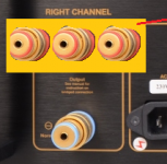
Can someone explain how a.FHXL "works"? Basic acoustic engineering?
- By Murrfk
- Full Range
- 21 Replies
I am nearing completion of building a FHXL. I have no idea what the horn is, or why this has its particular design. It would appear that the driver is placed so that half of the sound "goes" over the top into a wedge shape that dead ends. What is the purpose of that wedge? What do the slopes sides do, and why are they critical? What dimensions are cricical? What is the purpose of the fill, and how does fill "work"? If anyone can provide me with a basic understanding I would appreciate understanding the "why" behind the design.
Thanks
Thanks
3-Way OB - get the best out
Hello!
I plan to build a 3-Way Open Baffle and want to get the best out of it. The goal is to make compromises that do not limit the sound quality to much.
My wishlist 😀
- Overall good dispersion (horizontally and vertically [WMTMW?]) with a smooth target curve (see Toole)
- Transient XO passiv
- Flat response
- Enough low distortion
I dont hear loud music (never more then 90db), because of my neighborhood.
General Problems with 3-Way OB are that one driver can only play for 2-3 Octave. My solution so far:
Bass- Low Mids:
Some years ago i have seen a speaker that goes incredible low in an open baffle because of a stimulated movement of the complete baffle (there was made some acceleration measurements). Click here...
For my bass section and the low mids i will use 2 or 3 of the Monacor SP-225 per side. (Probably i have to make some test with different baffle-sizes)
I think i could use the SP-255 in this way from 20Hz to maximum 600Hz!
Tweeter:
I think the best solution we can see with the BG NEO 3 (vertical position) on the Aino Gradient Speaker.
Alternative....
.... Radian LT2, Dayton PTMini 6 (They aren't able to crossover so low like Neo3 and if crossed higher its harder to get a smooth vertical dispersion)
..... Peerless OC16SC04 (Higher crossover-frequency and most worse dispersion of all alternatives because of big dipol-width at 7-8khz)
..... Peerless TC5FC02 (At Cone Breakup probably loose of a good dispersion on the baackside of the driver at 5 khz. Compared to this the Neo3 will hold up till 7 khz)
Therefore i think the best selection is the Neo3 (additionaly it has a good reputation) and when we need a better distortion because of a low crossover point probably the TC5FC02 could be a second option!
THE MOST DIFFICULT PART - WHAT COMPROMISES TO DO?
Filler (600Hz-2,4khz):
If we go to ask for the best dispersion, we take 4 of the Filler in a
W
MM
T
MM
W
configuratioin. The best 1,5" i have found:
1,5" Peerless by Tymphany TC5FC07-04
Alternativly Dayton Audio DMA45-4 but not loud enough.
Or only two of Tang Band W23-1287SI
As Info for the Peerless driver, the 'd'Appolito crossover-frequency would be 570Hz and 2,2khz. With these little drivers i can simulate a very nice vertical and horizontal dispersion.
Or is distortion and dynamic that bad, that we should go for something bigger?
Other Ideas?
Best regards, Tomas
FS: 4x Peerless 830452 XLS, 2x Seas T25CF002, 2x Seas W22EX001
For sale full set of drivers purchased for Linkwitz Orion speakers that were used only one time, then disassembled and put in box (were my dad’s, who passed away :-( ). Practically brand new except one tweeter does need new voice coil.
$1900 OBO takes all
Can ship or local pickup also OK (I am located in Rhode Island)
Thanks
$1900 OBO takes all
Can ship or local pickup also OK (I am located in Rhode Island)
Thanks
Replacing 9 speakers B52 matrix 2000. I need help please.
- PA Systems
- 7 Replies
Hi everyone,
I have 9 B52 Matrix 2000 systems, where I daisy chain them all to make this huge sub wall. Its about time to service them and I was under the impression that I could get more out of these by upgrading the driver. Someone recommended the Faitel Pro HP1010, or 18 sound 18’s because they can handle what the amp is feeding.
Currently the amp I believe provides 600w to the sub channel and 600 is spilt between the 12” highs. So my question is Is there a driver I can put in this box that will hit more powerfully, efficiently (less heat, friction), and lower than what is in these now? I think some of these are loaded with FSW or FTW eminece’s, rebadged.
Or can you recommend a new system that will crush this setup, (everybody always screams bassboss😀) That I can use 3 20a circuits.
Thank you so much!!
DAC to wich COM port?
- By Ryssen
- Digital Line Level
- 2 Replies
I just built a Soekris dam 1021 R-2R DAC.
But how do I found out wich COM port it is connected,I have at least 6-8 USB ports.Is there a commant in windows I can se that???
But how do I found out wich COM port it is connected,I have at least 6-8 USB ports.Is there a commant in windows I can se that???
Impedance of Passive Sub.
- By Surtsey
- Subwoofers
- 3 Replies
I recently took apart a Celestion CS135. After reading a review I was expecting a decent crossover but I was misinformed.
How does the lack of a proper crossover affect overall impedance?
How does the lack of a proper crossover affect overall impedance?
Attachments
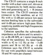
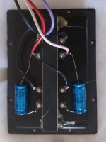
First Subwoofer, considering a PR
- By BrettAM
- Subwoofers
- 2 Replies
Hi all,
I've been thinking about doing my first small-medium subwoofer build and I'm hoping someone would be kind and patient enough to critique what I've come up with so far. This is a bit long winded as I'm trying to talk my way to a decision.
My project goal is for a -3dB in the mid-30s, with an overall volume less than 2cf. Maximum SPL isn't a priority. I already own a Dayton 100W plate amp that I'll start the project off with, but probably upgrade in the future. I have a budget of $200 or so for drivers/ports/etc, and I'm in Canada so driver selection tends to be a little more limited but Solen.ca is usually my go-to. I mostly played around with the Dayton Audio DCS255, DCS305, RSS(210/265/315)HF, and MX10.
I've already crossed sealed boxes off my list as I know I can't meet my goals without a massive box and/or DSP which I don't have the ability to do right now.
Finalist 1
Driver : Dayton DCS255-4
Box : 1.8cf, tuned to 32 Hz
Port : 4" x 16" round
Total Volume : 2.3 cf (includes port)
Ported seems like the obvious choice so this is my control, but when including the port my box volume tends to get larger than I want. This ones a bit large for me but I think I could make it work. Digs deeper than I need but overall pretty happy.

Finalist 2
Driver : Dayton DCS305-4
Passive Radiator : 1xRSS315-PR
Added Mass : 200g
Total Volume : 1.8cf
I was inspired to look into PRs when I came across the Meniscus Baby Boomer. I tried to match their claimed 30Hz F3 at 1cf but couldn't even get close. This was my best attempt using a single PR, and the PR costs more than the driver which seems a bit silly for me to consider and makes this the most expensive option. I'd also prefer dual PRs for the force cancelling property.

Finalist 3
Driver : Dayton DCS255-4
Passive Radiator : 2xDS315-PR
Added Mass : 200g
Total Volume : 1.3cf
Really happy with how small this is, but a bit of a hump in response. Might increase the box size a bit to try and get rid of it. Cone excursion makes me a touch nervous too but its at such a high power level I don't think it's a realistic issue.

Finalist 4
Driver : Dayton DCS305-4
Passive Radiator : 2xDS315-PR
Added Mass : 300g
Total Volume : 2.0cf
The added mass is right at the limit of what Greg at Dayton Audio said was "safe" but it still makes me a bit nervous. Excursion limits are under control and it digs nice and deep.

My current front runners are 3 and 4, with 3 taking a slight lead due to the smaller size. I might be able to tweak the sizes of both to get excursion and added mass lowered a little bit but I'm curious what I'm forgetting to consider, and what the more experienced individuals would do differently.

I've been thinking about doing my first small-medium subwoofer build and I'm hoping someone would be kind and patient enough to critique what I've come up with so far. This is a bit long winded as I'm trying to talk my way to a decision.
My project goal is for a -3dB in the mid-30s, with an overall volume less than 2cf. Maximum SPL isn't a priority. I already own a Dayton 100W plate amp that I'll start the project off with, but probably upgrade in the future. I have a budget of $200 or so for drivers/ports/etc, and I'm in Canada so driver selection tends to be a little more limited but Solen.ca is usually my go-to. I mostly played around with the Dayton Audio DCS255, DCS305, RSS(210/265/315)HF, and MX10.
I've already crossed sealed boxes off my list as I know I can't meet my goals without a massive box and/or DSP which I don't have the ability to do right now.
Finalist 1
Driver : Dayton DCS255-4
Box : 1.8cf, tuned to 32 Hz
Port : 4" x 16" round
Total Volume : 2.3 cf (includes port)
Ported seems like the obvious choice so this is my control, but when including the port my box volume tends to get larger than I want. This ones a bit large for me but I think I could make it work. Digs deeper than I need but overall pretty happy.
Finalist 2
Driver : Dayton DCS305-4
Passive Radiator : 1xRSS315-PR
Added Mass : 200g
Total Volume : 1.8cf
I was inspired to look into PRs when I came across the Meniscus Baby Boomer. I tried to match their claimed 30Hz F3 at 1cf but couldn't even get close. This was my best attempt using a single PR, and the PR costs more than the driver which seems a bit silly for me to consider and makes this the most expensive option. I'd also prefer dual PRs for the force cancelling property.
Finalist 3
Driver : Dayton DCS255-4
Passive Radiator : 2xDS315-PR
Added Mass : 200g
Total Volume : 1.3cf
Really happy with how small this is, but a bit of a hump in response. Might increase the box size a bit to try and get rid of it. Cone excursion makes me a touch nervous too but its at such a high power level I don't think it's a realistic issue.
Finalist 4
Driver : Dayton DCS305-4
Passive Radiator : 2xDS315-PR
Added Mass : 300g
Total Volume : 2.0cf
The added mass is right at the limit of what Greg at Dayton Audio said was "safe" but it still makes me a bit nervous. Excursion limits are under control and it digs nice and deep.
My current front runners are 3 and 4, with 3 taking a slight lead due to the smaller size. I might be able to tweak the sizes of both to get excursion and added mass lowered a little bit but I'm curious what I'm forgetting to consider, and what the more experienced individuals would do differently.
How to disable bluetooth reception on TPA3116 board?
I bought this Board with Bluetooth 5.0:
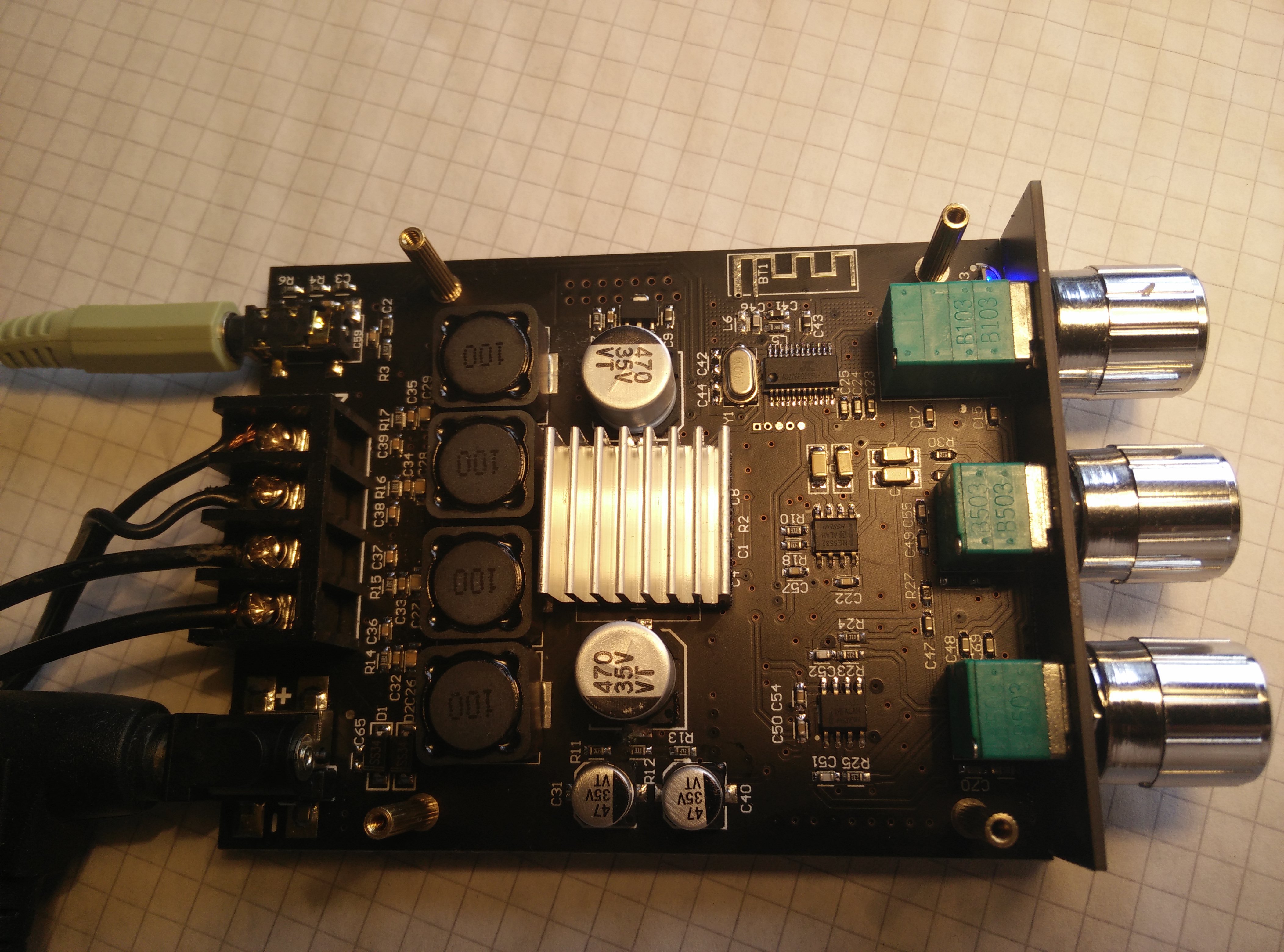
which works great but unfortunately it is always possible to connect devices even when the 3.5mm Aux is connected.
Is ist somehow possible to disable Bluetooth (preferable temporary by switch
disconnecting antenna or something)
The Bluetooth Chip is an "JL" AS20BP00966-25A4 "JL" stands for ZhuHai JieLi Technology Co (珠海市杰理科技股份有限公司-珠海市杰理科技股份有限公司|杰理芯片)
the chips is likely either an AC6905A or AC69025C (most likely last one because of BT5.0)
the chips would have the following pinouts:
System tuning vs Perception and Finding Neutral
- By camplo
- Room Acoustics & Mods
- 10 Replies
OK, I subscribe to a more scientific approach to the idea of what SQ is...In a perfect world a Razor flat system measurement at listening position probably would interest me. etc etc bla bla bla....Perfect flat is not achieved in our rooms (mastering studios control rooms etc) but a best as possible of maybe +/-1.5db in a really critical listening environment? +/-3db elsewhere? I dunno...whatever is possible is fine and not my issue. We use measurement microphones to tune systems. A microphone is not the ear, and there are enough differences to start a whole, other, debate lol....non the less...my point is this! Why wouldn't I be better off, tuning my system, aiming at as flat as possible, using my ear.....instead of a microphone....my thinking is that everyone has there own personal "frequency response" and that with practice....you would achieve an even more natural system FR, than a microphone could....
Maybe using a signal generator?
I can't be the first person to have thought of this and I am curious to where this discussion goes.
Maybe using a signal generator?
I can't be the first person to have thought of this and I am curious to where this discussion goes.
Heatsink tempertures/transistor performance
- By poundy
- Solid State
- 14 Replies
Ive been measuring the temperaturs of the heatsinks on the amplifiers ive neen working on over the last few months, and they are all very different, but the one im working on at the moment has a very high temperature (53c)
most i have worked on get up to at most the mid 40's
can this affect transistor performance and eventual quality of output?
so a bit like a PC processor, the hotter it gets the less efficient, without the heatsink and fan it would soon fail, as would the transistors
with the processor it slows as it gets hotter, or too hot and i wondered if the same could happen to BJT'S?
D&B D12 amp and Q1 loudspeaker matching
- By olivierr91
- PA Systems
- 4 Replies
Very newbie question here. I am buying my first line array for small venues (<1000 people).
The Q1 is rated 400W RMS @ 8 ohms. The D12 is rated 800W RMS per channel @ 8 ohms. So in theory, the D12 is able to power exactly 2 loudspeakers per channel. Am I right? The 2nd loudspeaker will be connected in the line-thru of the 1st loudspeaker, and putting the D12 amp in Q1 preset should do the correct impedance and crossover settings, right?
Just want to make sure I am not underpowering or overpowering the speakers.
Thanks
-
Locked
AEM6000 Based 50W Amp
- By platon.rado
- Vendor's Bazaar
- 0 Replies
The AEM6000 is an extremely well regarded amplifier making use of Hitachi
lateral MOSFETs. It was designed by David Tilbrook as a successor to the
ETI477, and published in Australian Electronics Monthly in the nineteen
eighties.
With changes in availability of components, the AEM6000 is now extremely
difficult to build. The amplifier was designed prior to the widespread use of
modelling tools, so is not optimised. Additionally it makes use of a large
single-sided PCB, with through-hole components throughout, like most kitset
amplifiers of the period.
This marks my fourth iteration of this amplifier. My first was reasonably faithful
to the original, differing mainly by substituting 2SK1058 and 2SJ162 flatpack
lateral power MOSFETs for the TO-3 devices in the original, plus substituting
an SST-404 dual JFET for the original input JFET. Iteration two was simply a
50W version of iteration one. This and the iteration three design (100W) alters
the topology slightly, dispensing with the differential-symmetrical VAS stage in
favour of a simpler non-differential stage. VAS and second stage transistors
are higher-performance 2SC3503 and 2SA1381, and the compensation
networks and biasing is optimised for increased amplifier speed whilst
reducing quiescent consumption
Power supply 4x4700uF. Bias 65mA,offset 5mV.
Specifications
Power handling: 50W RMS into 8Ω load.
Frequency response: +/- 0.1dB from 20Hz to 20KHz.
Gain 16 (stable with gain as low as 6).
Distortion + Noise: <0.0005% (1KHz, 0.1W to 50W into 8Ω).
<0.003% (10KHz, 0.1W to 50W into 8Ω).
Noise (input referred): 8nV/√Hz (measured at 10KHz, input shorted).
Slew rate: 10V/μs
Input impedance: 100KΩ (set by resistor).
Size: 75mm x 50mm PCB.
Power supply requirement: 2 x 40-60V DC. Lower voltages possible.
Idle power: 5.6W with +/-40V supply.
Price 90€
Attachments
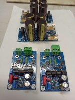
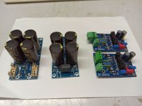
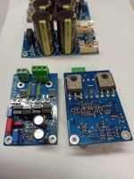
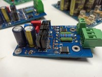
Eton silk some vs the Magnesium Ceramic Dome?
- By Jeffrey 01
- Multi-Way
- 4 Replies
Good afternoon everyone..Happy 4thof July. So I have never used a Eton tweeter before? I have use seas textile domes.and other planner and tweeter's and the L.G. metal some tweeter's from the past..So I have a few questions? I would really like to use the Eton magnesium ceramic dome model number 29HD2. I also like the sound of the silk Dome model number 28SD1. So can anyone tell me how the Magnesium Ceramic tweeter's sound like?Are they bright or tinging sounding? Thanks Jeff
Converting active monitors to passive
Hi everyone
I have these Neumann KH120 studio monitors, I quite like the sound but there are some reliability issues.
A while ago one of the monitors died. The problem lies within the smps.
Before that I had a customer bringing another one with the exact same problem, and on the internet there are several reports of smps failures.
I am not inclined in paying the official repair centre to fix the monitor and then having the same problem again at some point in the future.
I won't get much money for the broken speaker so I am starting to think I could have a play with it removing the whole psu + amp board and converting the speaker to passive.
I am totally new to crossover design so I am wondering wether this project would be worthwhile at all.
Very keen in knowing any opinions from who is more experienced in this subject
Here are some specs for the KH120 active monitor
NEUMANN
Breakups are the hardest thing to do!?
I've always wondered about how far I should drive breakups.
Some say 20dB is enough, others say 30dB, others go for 40dB or more.
after the driver (eg. Tweeter) overlaps, how much does masking affect the ability to hear these breakups?
Here's my driver + LP filter. Measurement conditions 0.5m, on baffle. Equivalent to 90dB/1m.
Are my breakups adequately suppressed? Perhaps this is one of those things where I need to test empirically with a DSP...
Attachments
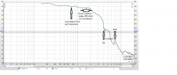
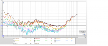
LEMF & ACE
- By merovingio
- Subwoofers
- 3 Replies
Hello everyone.
I have implemented a version of the LM3886 & ACEBass amplifier on the same circuit using the AudioPRO b1-45 circuit.
I saw an alternative called LEMF, has anyone implemented it? I would like to try it but I am not clear how to do it.
Thank you all.
I have implemented a version of the LM3886 & ACEBass amplifier on the same circuit using the AudioPRO b1-45 circuit.
I saw an alternative called LEMF, has anyone implemented it? I would like to try it but I am not clear how to do it.
Thank you all.
Tango line output transformer 8K : 600ohm
I consider to sell Tango custom transformers
8k / 600ohm 60H suitable for line output, preamp linestage with 5687 or as I planned - 46 type tube
can size of Xe20s
no discounts, no exchange, fixed price.
550 EUR TOTAL within EU
8k / 600ohm 60H suitable for line output, preamp linestage with 5687 or as I planned - 46 type tube
can size of Xe20s
no discounts, no exchange, fixed price.
550 EUR TOTAL within EU
Load more
Projects by fanatics, for fanatics
Get answers and advice for everyone wanting to learn the art of audio.
Join the Community
507,689
Members
7,884,368
Messages