Separated Aleph 5 (Butchered?)

Hi all. I'm starting to put an Aleph 5 together and have ran into some questions I figured I'd run by the folks over here.


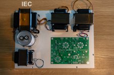
If you care to know the reasons why, you can read on after the questions, but suffice it to say that my build is going to be 3 boxes: 1 P/S sitting on the ground and 2 mono blocks getting their DC feed from the P/S. Obviously the amps will not have IEC ground as that'll only be on the P/S. The questions:


1. Should I still do an isolated star ground in the amps? Or is it okay to liberally use their chassis for ground?
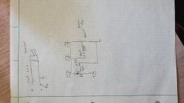
2. Should I duplicate everything from the P/S after the coil in each amp? Or should I go ahead and finish the P/S outside the amps and just supply the final voltage to each amp?
3. Am I okay running my DC power from the P/S over to one amp and then the other?


Thanks!


The reasons:

So, after reading posts for a few weeks on DIY Aleph 2 I finally decided that I couldn't stomach a 600W heater for 8-9 hours a day, 5 days a week, so I decided to take the plunge and settle for a 300W heater instead. The decision wasn't an easy one, since my NHT 3.3 speakers are only 87db SPL and would have appreciated the Aleph 2, but I decided that I'd instead do passive bi-amp, keeping my ATI AT-1502 for the subs and the double A5 for everything else. That would bring my overall power requirements much lower, since the 3.3 splits the woofer at 100Hz and 60W for everything above that should be fine..


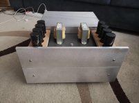
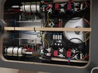
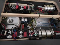
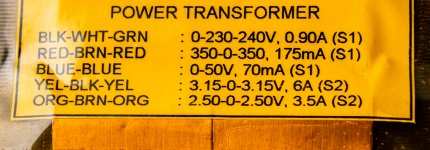
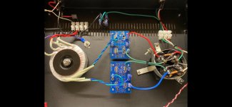
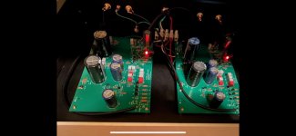
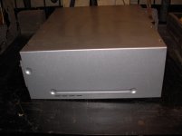
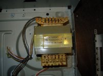
One of the things I wanted to do, since aesthetics don't mean much to me (although I love the stock look of the A2 and A5), was to separate the P/S from the amp, per one of Nelson's preferences. So after reading much I settled on a 30-0-30 1000va transformer (hoping it'll be +/- 37v) and running +/-V over to the amp. Then I thought purchasing a massive chassis with nothing in it seemed like a silly idea, so I decided to do 2 very small chassis. Each comes with 2 heat sinks of 0.36 C/W each, so my total after 4 heat sinks would be 0.09 C/W which I think should be able to handle 300W without any issues. The chassis run 10" wide and would sit side-by-side.


I'm still trying to figure out how to do volume matching between not only these two amps, but also between this set and the ATI that is going to drive the subs, because I'm using a home-made passive preamp with just one volume control and no balance, so I may have to do an op-amp with a volume control when I build the two A5s to feed the existing amp.

Help me re-engineer my 2A3 amp.

I bought this of eBay a few years ago as I figured it was priced not much more than the cost of the parts, and I had a 2A3 itch. It has worked reliably, it came with JJ tubes, I got some Sovteks for day to day.
It was never very convincing though. I recently acquired some Sonus Faber Electas. The 2a3 will, says with gritted teeth work nicely with the Electas, bit they don't. So I finally measured the amp today, it is significantly rolled off at the top and bottom, and manages a whopping 1.5 watts with the Sovteks, and 2 watts with the JJs.
I have been plotting their reinvention for some time, and have just got some ISO FC20s, and am open to ideas for a circuit, but I feel maybe a three stage with SRPP driving the grid, or maybe fixed bias and a cathode follower for the grid.
attachment.php

attachment.php

Attachments

  • IMG_20210709_191347.jpg
    IMG_20210709_191347.jpg
    123.3 KB · Views: 1,180

Balanced Output PCB

I'm wanting to add balanced outputs to some of my pre-amps. I've read the Jensen document and am planning to use the 'simple alternative', which I'm attaching for convenience. This just involves adding two resistors and a capacitor to balance the impedence.

Since this question comes up often enough, I'm thinking it would be worth it to make up a simple PCB that would contain the required components. The other two attachments show how this would go in the context of the Pass B1 Korg and then just the parts that would be on the PCB. Of course the actual board would be designed so that any values could be used. Can someone verify that I've got this right before I fire up KiCad to build the board?

One slightly unrelated question about KiCad, in case anyone reading this happens to know: How do you add mounting holes?

Attachments

  • Balanced.png
    Balanced.png
    27.6 KB · Views: 557
  • B1K-Bb.png
    B1K-Bb.png
    32.1 KB · Views: 355
  • B1K-Bc.png
    B1K-Bc.png
    21.1 KB · Views: 353

Like the old Chicago / CTA? These people are GOOD

I stumbled across a random video on Youtube, then spent most of the morning watching every video in their catalog and following some of the links.

This band is mostly from the Ukraine, Russia or eastern Europe, English is not their native language, and they have never seen any of the "Chicago" incarnations play live. Somehow they have learned to play old CTA stuff better than the current "Chicago" does.

(I've Been) Searchin' So Long - Leonid & Friends (Chicago cover) - YouTube

25 or 6 to 4 – Chicago (Leonid & Friends сover) - YouTube

Questions 67 & 68 – Chicago (Leonid & Friends cover) - YouTube

Leonid & Friends | Official Band Website

Input Impedance a Problem?

I currently have a Topping E30 DAC connected to a Schiit SYS (10k volume pot box) connected to a Hafler DH-101 preamp (using for tone controls since I’m hearing impaired and my idea of “neutral sounding” may be different than yours) and that is connected to a Hafler DH-120 amp (22k input impedance) or sometimes another amp with a 47k input impedance. The output level of the DAC is so high that the volume level of the preamp is either all the way off or too loud, hence the Schiit SYS pot box inline. Interconnect cables are very short, the longest being 3’ from the Hafler preamp to the power amp.

Having wired the preamp myself and looking over the schematic, the signal from the DAC/pot box goes directly through the DH-101’s own internal 50k volume potentiometer before it goes through the active high level gain stage. The DAC does have a remote and digital volume control (It can be put in pure DAC mode or preamp mode.) Should I just use the preamp mode instead? I bought the Schiit SYS since my other DAC (Schiit Modi 3+) is fixed line level out only. The Modi 3+ has an output impediance of 75 ohms. Since the Modi 3+ and SYS are wired in what is basiaclly series, it’s 5.075k ohms maximum (Schiit’s website says the SYS’s output impediance is 5k ohms maximum.) correct? I’m not sure what the output impedance of the Topping E30 is, but it would be xx ohms + 5k (max).

I ordered a Schiit Loki Mini+ a few days ago and my plan is to stop using the DH-101 and just use whatever DAC (Modi 3+ or E30), the SYS, and Loki Mini+. Is there a correct way to connect these 3, or does it not matter? I was thinking DAC > SYS > Loki Mini+ > power amplifier. Or do I want the DAC connected to the Loki Mini+ and then the Loki Mini+ connected to the SYS?

Attachments

  • A0E4C576-9D84-41B8-8B7A-DFAF0F8084A4.jpeg
    A0E4C576-9D84-41B8-8B7A-DFAF0F8084A4.jpeg
    258.6 KB · Views: 93
  • 9751B828-5558-4C3D-8261-E8CCF750D30F.jpeg
    9751B828-5558-4C3D-8261-E8CCF750D30F.jpeg
    665.9 KB · Views: 92

Woofer and Subwoofer sharing airspace?

I have asked this question before and been told that it is ill-advised but I suspect the answers are led by the lack of facilities to calculate.

Logically, two 6.5" woofers in a 20l cabinet will perform better than one. By the same logic two 6.5" subwoofers in that same cabinet will perform better than one. Subsequently, one subwoofer and one woofer will offer better bass performance than two woofers. Perhaps lower the bottom end by 10hz?

I ask the question because many floor-standing speakers appear to be a waste of volume.

The simplest solution would be to wire the drivers in parallel. However, a rumble level high-pass filter on the woofer could be used, but this brings the passive radiator effect into the equation.

What factors govern the frequency response of a driver? e.g. If I feed 25Hz into the sub driver it oscillates wildly, The same signal into the woofer is largely ignored.

Thoughts.

FS: 4x AK4137EQ

After months of seeking the AK4137EQ all over the possible places, I finally managed to buy 5 pieces still sealed in reel. I do have to pay an overpriced total for them though, not a surprised at all. These all come from a shop in Japan. I only share 4 of them, want to keep one for my DSD-PCM build.

Price is $48/ea plus fee and $15 shipping by Registered Airmail. Unfortunately I'm not able to ship to destinations that have very strict custom like India or Russia.

An externally hosted image should be here but it was not working when we last tested it.

Newbie - 2nd Strike - idea - thumbs up or down?

Hey People!


As I like diy and music, I was hooked from the first second. They're not really complete yet, but right now I'm hearing Nick Cave with my first diy speakers and it' great. It's a 2.1 - 7-channel fully active 2.5-way + SW system with chipamps built on a pretty low budget, but it sounds just wow!


Sure I'm thinking of what could come next.
One of the many ideas could be the next step getting deeper in "real" diy audio. I have no experience, therefore I ask you.


What do you think about a FAST, with Dayton PS220-8 ( 404 Not Found ) and built in Pass Class A mono blocks (and a 12 or 15" active SW).


Hell yeah or let it be?

Audient iD14 and Kenwood Basic M1 matching

Greetings,
trying to understand i/O voltage/Impedance matching:
to explain:
1) purchased Kenwood Basic M1 Amplifier, and Basic C1 Preamp; very satisfied
M1 Amp: Input sensitivity: 1 V 47KΩ..
C1 Preamp: "Output Voltage & Impedance: 1 V/less than 600Ω, maximum output: 5V Load Impedance: 47kΩ"... everything wunderbar

2) Went shopping for additional Basic M1 (for my workshop), purchased via Ebay, UK
M1 Amp purchase also included Basic C2 Preamp (oh goody! lots of extra features!):
C2 Preamp: "Tape Rec: 150mV, 220Ω", PRE OUT: 1,000mV, 100Ω"
Assumed was included in Kenwood Basic series, was compatible...
However, at approx. 1/3 - 1/4 volume... distortion extreme (mis-match... really stupid move by Kenwood??)

To the Point:
Audient iD14 as DAC/master volume control:
(one audio source: my PC/TOSLINK)
"Maximum output level - +12dBu (0dBFS digital maximum)"
"Output Impedance <100Ω"

Audient iD14 has Balanced TRS outputs - intend to use unbalanced TS-RCA adapters

Is the iD14/M1 Basic combo a mismatch problem? (haven't tried it yet... would really hate to brick something)
solved with HiZ/Loz adapter? or DI box (before the Amp)
thank you for a useful recommendation (if this works, C2 will become a doorstop or boat anchor)

Parasound DAC 1600HD mods

I finally got around to a modification to my DAC1600 and was wondering if anyone else has tried the same.

I do not use the balanced outputs, since the rest of my system doesn’t support it. I had decided early on that I could pull the unused complimentary PCM63s and stack them onto the existing chips. I was hoping to see how much better/smoother the DAC could be.

Before I pulled them I reviewed the schematics and realized that the complimentary ‘balanced’ half of the circuit was identical to the ‘unbalanced’ circuit with the exception of running the signal through a hex inverter to make the signal a mirror image.

I decided in the end to try and remove the inverters so both chips pass the same signal and sum them after the IV stage at the XLR jack with a custom cable. Tests proved that this worked and is easily reversed back to stock if I ever wanted to.

The difference is subtle, but noticeable if you look for the differences. I have especially noticed that some background acoustic guitar picking sound much more realistic than the stock unbalanced unit the guitars went from sounding ‘hard’ and like steel strings to much more detailed ‘gut’ strings with better attack and decay.

Ultimately I have just created a jumper plug out of an old XLR connector, which sums the two signals and can be passed through the standard unbalanced jack with my normal interconnects. The unbalanced jack shares a trace with half of the XLR so making the jumper plug just connects the two signals which pass it to the unbalanced jack. Pulling the jumper reverts the unit back to a stock unbalanced output so A/B testing is also not too difficult.

Has anyone ever done a similar modification to their DAC? I’ve searched the web but didn’t find anyone who summed the signals after the opamp/buffer section.

Reliable source for BF862 ?

Hi guys,


as the title say's, I need original BF862 for a project I'm working on.
Interested in quantities of +100pcs and more.

Anybody care to share their stash or point me to a seller that is legit ?


Currently I have more then 1k fake jfets laying on my table from failed attempts on eBay and Ali and although I got refunds for most of them this is getting really frustrating 🙁


You guys are my last hope 🙂

Attenuator for Headphones?

Hi,

I have recently bought a Tascam LM-8ST line mixer, which has a headphone output on the front. However when I use my Beyerdynamic DT 250 headphones with it, the output is far too loud - and I end up only using the very bottom of the volume control.

DT 250 Impedance: 80 Ω
LM-8ST Headphone Output: 250 mW + 250 mW (32Ω)

While I know that beyerdynamic also make a high-impedance version of the headphones - I am slightly surprised by the how big a mismatch there is.

I would like be able use the full range of the headphone control (without destroying my ears). Would some kind of attenuator circuit work? How do I calculate the resistor values?


Thanks!

njh.

Power Supply, Ripple, Noise Floor Questions

Hello--

I borrowed an oscilloscope from a friend recently. Actually, not much of an oscilloscope at all--a dinky DIY kit. Minimum sensitivity is 8 mV, maximum input voltage is only 50V. That leaves me able to test the signal outputs of my components. I've consulted a number of sources (Radiotron handbook, https://dalmura.com.au/static/Hum article.pdf, Neurochrome's articles, Eli Duttman's site), I'd like to bounce a few measurements and some questions off of anyone whose willing to lend some of their time.

On my integrated tube amplifier, for example, I measure 8-10mV pp with the volume knob at 0. So I am at the minimum measurable threshold of the oscilloscope. It shows a 120Hz waveform there. Through my ~88dB monitor speakers, I can hear this with my ear near a cone. It does not increase with volume. I can swap in other tubes and measure anywhere from 12-30mV pp with them.

When I get the volume control at about 75%, or 12 o'clock, a 60Hz waveform appears. This increases with volume and by 100% can bump the measured voltage to about 50-60 mV.

The 120 Hz waveform is the ripple in my rectified DC, correct? The amplifier is SE 2A3 transformer coupled output with two gain stages. Each 2A3 has its own DC supply.

So the point of the post is to try and understand the sources of the noise and how much I can expect to do about each.

Obviously the answer varies with speaker sensitivity, but within reason, what mV (or sub-millivolt?) measurement of the noise floor should I be aiming for?

Is the 120Hz waveform from the B+ going into the output transformer and/or the B+ ripple on the two gain stages and/or ripple from the filament DC?

With regard to the 60Hz noise, which I am 99% sure is from the input stages AC heaters (all indirectly heated triodes): Is it possible that a humdinger on the 6.3V transformer secondary (artificial) CT would be able to "null" this noise source? Obviously, switching from AC to DC supply for the heaters would eliminate that noise source, so perhaps it's best to pursue this approach. I am assuming that none of the 60Hz noise is coupled from, say, the heater or primary TX, but I have reason to believe that any 60Hz coupling is minimal. Both TX are toroids; one is mounted on top with an iron shield; the other is mounted underneath but very far away from OPT or signal circuitry.

We recently moved our audio room and discovered that in the new location, if we have our dining room dimmer-switch canister lights on, we can hear a very harsh buzzing noise in the amp. It's not a big deal for us to have the lights off in another room when we listen to our amplifier, but for my own edification, is this a noise source that adding a snubber to the power supply would mitigate?

Lastly: We live in an old house. Unless I run a line from our breaker box in the basement (which I did), there is no grounded 3-prong outlet available to us. Before I installed this electrical line, the noise floor of my components was much higher. On tubed gear, I could put my hand near input tubes and generate substantial hum in the output. What exactly causes this? Is this the potential voltage difference between myself (standing in my socks on a wooden floor; components mounted on a wooden shelf) and the voltages present in the amplifier interacting via capacitance? (I could be way off on this last point, but would really like to understand!)

Thanks for your time!

Valve amp inrush question

Hi,
I have just finished my new valve amp and I am now aware that there is a large inrush current.
300bPS.PNG
Here the HT is connected to a GZ34 and then CLC, and the filament supplies a Rod Coleman regulator.

The question I have is, can I just add a thermistor straight after the plug (as shown above), and if so, can someone tell me exactly which thermistor I should use?
Thank you so much - I feel very old to be a noob, but hey ho.
Thanks again
Bass

Buzzing mains transformer - what helps?

I have a buzzing mains transformer on a SE amplifier. It's an old transformer. I've read up on some things to do like re-gluing laminations, dipping it in shellac and methylated spirits etc. But are there some simpler things that will lessen the buzz? For instance:

- Mount it on rubber feet
- Insert bolts into any unused holes and bolt the laminations tighter?
- ??? anything else

The transformer is a good size and doesn't get hot, so though there's no markings to identify it, it shouldn't be stressed.

Photovoltaic Inverter ?

Mains 230 V Photovoltaic Inverter = Class D !?!

A friend's home mains tied PV inverter just failed and the solar power companies seem to do no repairs, just sell a new one, so I scored the old inverter.
It's an Aurora PVI 3600-AU, as you would expect from the model code it's 3600 watts, Australian 230 V model.
It may not be repairable, it's all driven by a micro controller and there's no source code, or schematics, or service manual, AFAIK.
But the failure was an "Over Temperature" even with no sun and the inverter stone cold so maybe just a bad temperature sensor
In any case it should have some useful bits inside and it will at least be educational to pull it apart.
The inverter core is basically a 3.6 kW Class D amp that is fixed on 50 Hz so I wondered if anyone here had pulled one apart?
What does the screw labelled "Warranty Void if Removed" do?😉

David

Revox G36 120 vs 240 Tape Speed

I recently obtained a Revox G36 reel to reel that started life in a 50hz, 240 VAC environment. The machine came with a 120 to 240 volt step up transformer and old recordings made on the machine appeared to play back at the correct speed using the transformer. I'd prefer not to use the large transformer so I set up the machine to run in its 110 volt setting. The problem is that running in the 110 volt setting, the machine is recording and playing back way too fast. This was verified by playing back a recent Revox recorded tape on a different, fully calibrated machine. I have to assume that plugging a step up transformer into a 60hz 110 volt power source would yield 240 volt, 60hz power which leads to several questions. Would a 60hz power source cause a 50hz motor to run way fast? Will I need a different capstan or capstan motor for a 110 volts? Should I just blow off the idea of not using the power supply and if so, why would the machine run at the correct speed on 240 volts or the wrong speed on 110 volts? Any input about this would be greatly appreciated. Geoffrey

What DIY Amps are available for Stax?

The only two that I am aware of are the KGSSHV, and the Blue Hawaii. Unfortunately, it appears that Kevin Gilmore's website was taken down when he retired from Northwestern, and that had the BOMs and schematics for both of those amps. I'm also unsure if it's even possible to get boards for these amps anymore.


Are any fellow Stax enthusiasts able to shed some light on this?

bare copper wire (soft) 0.4mm and 0.5mm ?

I didn't realise that I was running out of both of these and have to put on hold rebuilding my Heybrook speakers and i/connects.

Used to use a very good supplier in the UK but with July 1st came ramping up of prices with TVA being added and a rip-off customs inspection price to boot.

So I go looking for a supplier in the EU, preferably in France where I live . So I checked out RS.fr couldn't find what I wanted so look at RS.uk - no problem got what I want but then there's postage and of course 20% EU import charge and TVA added on total cost. Why isn't the same product available on the French site? I want 40 M of 0.5mm & 0.4mm. I don't want industrial quantities.

Take note 'bare' not enamelled wire.

Simple CFA for High Frequency

Hello,

I'd like to make an amplifier for High Frequency (500kHz-1MHz), with AB topology and 5-10W over a resistive load of 20 ohm.
It's not for audio application, just for research/lab fun.
I used a CFA amplifier, with the attached schematic.
I need it is simple, working and easy to made in a PCB.
What do you think about this schematic, anything wrong, something to add/modify?
Thanks

Immagine — ImgBB

recommendations for 12V class-d board

I'm in search of a quality mono class-d amp board to be powered from vehicle or AGM battery 12V power. What would you recommend, or can you point me to a vendor, or a diya thread?
Right now my choice is one of the TPA3116/18 boards with PBTL out.
Bluetooth would be nice, but can be added separately.
The amp will be integrated into a portable powered speaker, an 8-ohm Bose 301 to be exact.
Any help would be most appreciated.

Cordell capacitance multiplier current capability?

Hello,

I'm thinking of implementing the cap multipliers from Bob Cordell's VinylTrak along with a SMPS for low-power circuits like headphone amps.

This is the link: http://www.cordellaudio.com/preamplifiers/vinyltrak.shtml

And the schematic:
fig4.jpg

My question is how much current is this capable of delivering? Will one of these be suitable for powering 4 op amps?

SymAsym 5.3 amplifier for sale

Completed with top parts and CLC power supply with 53000uf-L-26000uf.All capacitor Kemet screw typ wit verry low Esr. Input capacitor Siemens Mkv 4,7uf.Amplifier is about 20kg heavy so the shipping would be about 70-80euro in EU. Amplifier is without hum or hiss, and sound superb. Price would be 500eu plus shipping. Or best offer.

Attachments

  • IMG_20210712_123713.jpg
    IMG_20210712_123713.jpg
    788.2 KB · Views: 191
  • IMG_20210712_123721.jpg
    IMG_20210712_123721.jpg
    459.4 KB · Views: 196
  • IMG_20210712_123800.jpg
    IMG_20210712_123800.jpg
    590.8 KB · Views: 188
  • IMG_20210712_123851.jpg
    IMG_20210712_123851.jpg
    684.1 KB · Views: 193

Seeking help, unusual CD problem

Hello everyone!
Here is the scenario: Creek CD43 MkII player, with the obnoxious Philips CDM 12.1 mechanism. Reding and playing is erratic, skips, some discs -mostly CDR-s- not even recognized, etc. Well, this usually indicates a weakening laser head.

Then comes a brand new VAM 1202 (theoretically fully intercangeable) mechanism, and here is the twist:

With the new one, newer CDR-s and factory original discs rejected (laser starts, disc spins, then: "no disc"). BUT! Really old CDr-s with blue and green substrate material read and played flawlessly..... 😎 Seems like it can recognize only those 15-18 years old crappy written discs.
Any idea? Maybe too much RF output from the head amp? Unfortunately I cannot measure eye pattern because my scope is half dead.....😡
Also, service manual is unobtanium...

Autotek ss750.1

I'm working on an Old-school autotek and have rebuilt the PS new fets and gate resistors. The trouble I am having is, if i apply the remote the amp draws massive current and the tl494 does not generate pwm. But if I pulse the remote on and off a few times I get pwm and and the amp functions perfectly. I can even turn it off and on normally. But if I wait a few minutes, I have to pulse the remote again the same way. I have already changed the tl494. I have never run into this issue. Any ideas?

need assistance on SSE build

Hi everyone,

I am finally starting my SSE build, I got the pcb from George awhile back, 4-5yrs ago if my memory serves me right. Then life happened, moved to a new country, moved houses etc etc. Anyway, I am asking for assistance on my build and would appreciate any help I can get.

First question is about the power transformer, I got this PT which doesn't have the standard wire color coding used by Edcor or Hammond. It also has extra wires which I am not clearly sure where to hook up in the pcb or if they need be at all. Attached is a photo of the label underneath the PT.

Second question is about layout, attached is the photo of my mock up. the silver plate is the actual top plate of the chassis. Pls let me know if this is ok or if I need to move anything.

Thanks in advance.

Attachments

  • PT.jpg
    PT.jpg
    594 KB · Views: 301
  • layout_1.jpg
    layout_1.jpg
    896.2 KB · Views: 303

SE class A regulator-chip-amp madness

Here is the next in the series:
http://www.diyaudio.com/forums/chip...ator-chip-amp-family-welcomes-new-member.html

It is a (relatively) efficient class A single ended stereo amplifier utilizing the correlation between L and R channels to improve efficiency.

This one is a really top-class amplifier, boasting less than one ppm THD!

Have fun!!!

Attachments

  • SEchipAmp2.GIF
    SEchipAmp2.GIF
    13 KB · Views: 4,509
  • SEchipAmp1.GIF
    SEchipAmp1.GIF
    57 KB · Views: 4,367

Trying to figure out the alignment for JBL 2216ND-1

Hi all,

I am trying to arrive at a alignment and thus box / port size for the JBL 2216ND-1. The cabinet will be vented and the driver should handle anything from F3 (whatever it ends up to be) up to 1kHz. My goal is to have a good tight bass but at the same time not sacrificing F3 too much.

For the JBL 2216ND-1, a member in another forum measured a pair of 2216ND-1 to have:

T/S data measured from the first driver:
Re = 5.556Ohm
Fs = 28.26Hz
Qts = 0.376
Qes = 0.397
Qms = 7.12
Le = 0.461mH
Mms=134.1gr
Vas = 332.8liters

T/S data measured from the second driver:
Re = 5.52Ohm
Fs = 27.59Hz
Qts = 0.3572
Qes = 0.3776
Qms = 6.589
Le = 0.4703mH
Mms=123.8gr
Vas = 378.4liters

they differ a little as one is warmed.

I tried plugging into WinISD for a few different standard alignments.

SBB4 : 7.443 ft^3, tuned to 28.26Hz, F3=33.8, GD@40Hz=9.6ms, GD@30Hz=15.25ms
SC4: 8.869 ft^3, tuned to 29.48Hz, F3=30.5, GD@40Hz=10.6ms, GD@30Hz=18.5ms
QB3: 9.017 ft^3, tuned to 29.62Hz, F3=30.5, GD@40Hz=10.8ms, GD@30Hz=18.6ms

Those are pretty big boxes, but their FR is pretty flat with no hump. And supposedly they are the alignments with tighter bass.

QBB4 seems to be the most practical in terms of size.

What I still trying to understand is...

The JBL 4367 cabinet (where the 2216ND-1 is used) is way smaller than the QBB4. From the 4367 dimensions, I estimated it to be less than 5 ft^3. Is there something JBL knows? or is it just a marketing decision to go with a smaller box as a compromise?

SBB4 traded off 3Hz for a few seconds GD. I know 3Hz is probably audible, how about a few mseconds in GD?

There are also some stuffing in the 4367 cabinet. Is that something worth considering ? supposedly in closed box, it "adds" 10% effective volume.

What would be the sound quality difference if I go with a even smaller boxes? I know GD will go up which means slower and less tight bass?

I want to make sure the bass is tight good quality. If there is small sacrifice in F3, I can EQ it back. But how about a few ms in GD?

To offset or not to offset in TL

For those who have played around with woofers in TLs... As a practical matter how big of an advantage is there in using the 1/3 pipe length offset driver positioning? The application in view is a woofer (not subwoofer) enclosure to be used up to about 500Hz. The closed end driver positioning is much simpler and hornresp simulations of quite of few drivers seem to show more even response in the frequencies below the first resonance.

For a folded end loaded TL of this type with reasonable stuffing is the reduction of the first (or I guess actually second) resonance a huge practical advantage? If we are running up a few octaves higher is it really a big deal in the overall stuffing scheme? Also is it best to have unequal segment lengths in the folding and truly tapered walls rather than stepped?

Warm Up Indicator Circuit

Hi. I am building a tube amp and I want to incorporate a warm-up indicator light as shown in my schematic. It acts as a visual indicator that the amp is warmed up and operating and is mainly intended to avoid confusion from newbies to the world of tube amps who, being accustomed to the instant start-up associated with solid-state amplifiers and electronics, may be potentially mislead into thinking the amplifier is defective when it actually isn't just because it makes them wait up to 15 seconds after turning it on before it lets them hear anything!

My circuit takes advantage of the rise in output tube cathode bias voltage to trigger a relay (with a DC operated coil) that has its armature wired in series with a #47 light bulb (this is in addition to the "normal" power pilot light). As the tube or tubes warm up, the voltage rises past the minimum "pick up" voltage required to trip the relay and, just like the pre-heating light on an oven, this causes the warm-up indicator light to go out, indicating to the observer that the amp is in fact warmed up.

Actually, I cannot take all the credit for this design. This actually was partially inspired by the "quick start" function on old Wurlitzer jukebox amplifiers. This involves a cathode-voltage controlled relay, but instead of using it to operate a light, it is used to temporarily increase voltage to the tube filaments when the cathodes are "cold", and switch to the normal 6.3 Volts when the tubes have warmed up.

I've done some preliminary tests in LTSpice that give some guidance for the design.

1. In a zero-signal state, the cathode bias voltage must be above the pick-up voltage of the relay. Otherwise, the relay will not trip and the warm-up light will stay on after the tubes have warmed up.
2. In a maximum-signal state, the tube should not be driven to the point where the cathode voltage exceeds the maximum rated voltage of the relay coil. Otherwise, the relay coil may be damaged or burned out.
3. Since the relay coil is in parallel with the usual bias resistor (Rk), this reduces the net resistance the cathode "sees" (Rnet=1/Rk+1/Rcoil). Therefore, cathode resistor Rk must be made significantly larger in resistance (ideally more than twice as large) in order to properly bias the tube or tubes than if the relay were not present.

However, in my LTSpice simulations, I want to take into account the effect of the inductance of the relay coil on the rest of the circuit. Unfortunately, the coil inductance is usually nonexistent on most relay data sheets. Could you guys help me out here?

Any other improvements you guys recommend?

Attachments

  • warmupind1.png
    warmupind1.png
    45.8 KB · Views: 377

can you look at this sub for me?

Looking to make a marty/devastator box for the house.
Need the deep breath I am missing from my sealed 15.
It hits hard. and is great musicly.
But missing the thunder storm and the deep power.

Going to feed a PAIR of these 125 per coil
and use a pair of them.

Thiele Small Specifications

Revc = 3.400 ohms
Fo = 36.121 Hz.
Sd = 53.093 mM
Md = 60.000 g
Bl = 9.458T
Qms = 2.443
Qes = 1.225
Qts = 0.816
No = 0.431%
SPL = 90 dB
Vas = 115.926 mM
Cms = 289.613u M/N
Krm = 4.148 m Ohm
Erm = 0.793
Mms = 67.034 g
Mmd = 60.000 g
Kxm = 31.652 mH
Exm = 0.625


Looking to make a tall marty or devestator style sub and feed it 70hz and below only.

Wiring for Lundhal transformers - TU-8200R What I did.

I wanted to show how I wired my Lundahl transformers, as I like detail and input from others. In case someone is looking for instructions on these, here is what I did. Feedback and criticism are welcome.

1. First I installed the mounting plate. Make sure you have the bevel for the bolt facing out.20210520_093356_resize_2.jpg

2. Next I placed the circuit board on the Lundahl making sure it was flat20210520_093812_resize_58.jpg
20210520_093630_resize_41.jpg

3. I soldered the corners (top right and bottom left) and rechecked if that it was flat
20210520_093800_resize_8.jpg

4. Then I soldered the remaining leads
20210520_094116_resize_85.jpg

5. Next I thinned the pads for the wires to the connections.
20210520_094348_resize_27.jpg

6. The wires were stripped fairly long, so I cut about 3/8 (10mm) off each.
20210520_094459_resize_96.jpg

7. I tinned the wires
20210520_094734_resize_65.jpg

8. Here things got interesting. Do I solder the wires up or down. I originally soldered them towards the bottom, but that made them awkward to connect to the boards, so I resoldered them going up. The leads that connect to unit one have to go a long way, and I think they have to go up to reach, but they do pass close to the transformer. In the end I stayed with them going up, as shown I these images.
20210520_095311_resize_24.jpg
20210520_095350_resize_49.jpg

Let me know if you see any obvious errors
Hope this helps someone.

Pioneer VSX-D514 help

Hello everyone I am looking for some help if anyone could help me fix my Pioneer VSX-D514 amp.

It was working fine up to now and last week when switching it on the relays started oscillating meaning clicking on and off continuously until the unit switched off completely and would not turn on.

After a lot of turn on and turn off attempts it switched on. I checked the output there was only 2 mv DC offset and it stayed on without saying AMP ERROR or DC OFFSET. All normal

Tuned it off opened it, turned on, did the Advanced surround + Enter keypress and noticed the clicking relay was from the Main AC board. After that it would not turn on at all i.e. the relay on the main AC board is not longer working

I checked the voltages based on the service manual there is a proper +5V standby and i am getting 3.3V from the AC WK signal. Traced the AC signal path there is no blown fuse. Did also a check on the amp protection lines DC DET and overload lines are at zero volt. There is proper voltage at the relay pins but the relay driver transistor base is at zero volts.

Is there anything else anyone might suggest me to check? Thanks

Attachments

D3a pentode as driver? History of this tube?

D3A Pentode as drive?, history of this tube?

I ran across this schematic of a parallel 2A3 with a D3A as a driver (Redrawn from Audiodesignguide.com)....I can't seem to find any info on this tube!
Most of the more "common" tubes have entire colorful histories associated with their development. This D3A I can't find anything..what was it used for , when did it first come out et al.
_______________________________________Rick..........

Attachments

  • 2a3 parallel, pentode drive resize.jpg
    2a3 parallel, pentode drive resize.jpg
    56.3 KB · Views: 2,447

Driverack pa2 , dB-Mark XCA26, etc, etc

I am looking to purchase one of the two items, or maybe something different if there are better options for the task of speaker voicing and room correction. The Driverack has the most eq control points and the Db-mark has a higher sample resolution. Are there better products that I am unaware of within the same price range? I'm creating a 2 or 3 way system and need the active eq and crossover, and room eq might as well get done at the same time.

5v Precision Voltage Regulator using ADR02

Hi folks

I happen to have several ADR02 and noted in the datasheet that a Precision voltage regulator can be made using this chip plus an opamp and a mosfet.

attachment.php


The example with a 2N7002 mosfet gives an output for 50mA, which is a bit lower than I need, but it states that a larger mosfet can be used to get a higher output current. However, I don't know what parameter of the mosfet must be larger. If I wanted to create a regulator with say, 150mA output, how would I select the larger mosfet?

Also, the opamp used in an ADA4522, I take it because it is a zero drift type. Can a normal opamp be substituted as ADA4522 is rather expensive?

Attachments

  • ADR02 Boosted Output.png
    ADR02 Boosted Output.png
    50 KB · Views: 393

Improving Hybrid Guitar Amp - Johnson T15R

Hi DIYaudioers,
I was fortunate enough to find a cheap hybrid tube amp on the local buy and sell. It's my first tube amp and I'm a big fan of the sound.
Johnson Guitars Its a made in china combo amp that has an 12AX7 preamp stage.

There is a hum which I'm told is normal. It's nothing major but its noticeable to me coming from solid state amps. I took it apart an looked at the amp circuit and it's pretty easy to work on. On some other forums they suggest increasing the 47uF filter caps to a 100uF.

Just wondering if you tube wizards have any thoughts on improving this amp. I know nothing about circuit design but am comfortable with a soldering iron. May try the cap swap but before I go to the local electronics store figured I'd ask here.

Johnson Audio was nice enough to send a schematic (attached)

Any thoughts? Hope you can help!

Attachments

FS: Pearl 2 Phono - Pesante 2u in 10mm Black

For sale is a Pearl 2 Phono built in Pesante 2U 10mm black chassis'. It's currently set at 1K "user load" for MC cartridges. JFets purchased directly from PassDIY so they were closely matched.

It works and operates great. I just do not have the space anymore.

Asking $500 and i'll cover shipping.... CONUS only.

Attachments

  • IMG_4125.jpg
    IMG_4125.jpg
    644.8 KB · Views: 223
  • IMG_4124.jpg
    IMG_4124.jpg
    77.5 KB · Views: 228
  • IMG_4123.jpg
    IMG_4123.jpg
    60 KB · Views: 224

Active+passive crossovers for open baffle

Hi

I am thinking about building myself a pair of open baffle speakers. I am thinking about using my two crown xls 2002 amps and my moon 240i to drive them. The crown amps driving 12" woofer + 8" woofer and the moon for a fullrange driver. Crown xls have built in 24db LR filters so for example lowpass 250hz for the 12" and lowpass 500hz for the 8" and maybe a passive hipass between the moon and the full range driver. Is it all all possible to make this work? I can us EQ in roon if necessary.

My primary idea was to sell my moon and buy myself a minidsp 4x10hd and buy myself another cheaper amp for fullrange, alternatively two stereo amps for midrange and tweeter. The thing is I really like my moon and dont really know if it is worth to sell.

/Jakob

Definitive technologies sub help

I have an old Definitive Technologies Powerfield 18 subwoofer that died years ago. I am just getting around to fixing or moving on. From what I have found the transformer is bad. I need help locating a replacement transformer. I believe from the schematics the secondary output should be 66v. Maximum output 500 watts at 6 ohms. There are numbers on the transformer but Google search has come back with nothing on any of the numbers.

Any help would be great…..if this should be posted in another section please let me know and it will be moved.

Thanks

Antek AS-4T360 - 400VA 360V Transformer - $20

Just purchased an Antek AS-4T360 - 400VA 360V Transformer and will not be using it. It is still in it's original packaging. I am assuming that it is complete, complete meaning with mounting hardware. Asking $20 for USPS Priority Mail 2-Day Medium Flat Rate Box shipping. My on a whim purchase, your gain. Here are the specs:

Weight: 9.0 lb
Dimensions: 5.1" d x 3.1" h

Electrical Characteristics
Outputs 4x
Power 400VA
Voltage Current
360V 0.55A
360V 0.55A
6.3V 4A
6.3V 4A

Trimming a TH design

I would like to build the tapped horn design in this thread: https://www.diyaudio.com/forums/subwoofers/170771-single-sheet-th-challenge.html

However I would like to trim the width from 22" to 21" so it can lay flat in my truck and still close the bed cover. What is an acceptable way to make this adjustment? Should I scale all dimensions down by the same ratio or is it OK to reduce the width only?

Thanks in advance!

FS Case housing for amp or DAC with mains transformer Pioneer

DIY stuff
Pioneer dvd receiver - large
Any interest, I'll go measure it (but guess 20x20x6 inches)

Case [in good condition] and a few parts, incl. mains transformer;
a stiffener bar or frame inside, for solidity;
main face plate of plastic was broken, now removed - you need to cover the metal skeleton front

I assume it's pressed steel.
Case this size would be 50-100$ new.
See pics, please.

Post will be 27$ all of Canada

Attachments

  • DSCN2886.jpg
    DSCN2886.jpg
    436 KB · Views: 142
  • DSCN2893.jpg
    DSCN2893.jpg
    367.1 KB · Views: 134
  • DSCN2887.jpg
    DSCN2887.jpg
    357.8 KB · Views: 134
  • DSCN2888.jpg
    DSCN2888.jpg
    592.1 KB · Views: 135
  • DSCN2890.jpg
    DSCN2890.jpg
    405.6 KB · Views: 128

KEF Reference UniQ driver in ??? box? back-loaded horn?

I have 2 KEF Reference Uni-Q 6.5" drivers on hand and am looking for an enclosure and setup options for them. I would use them on my desk as near field speakers or possibly on stands in a living room area. These are the same drivers used through the entire KEF Reference series from the Reference 201 bookshelf up to the flagship model 207.

Part info: B160 Uni-Q SP1447
$_12.JPG


KEF Website link with models and drivers

KEF 203:
An externally hosted image should be here but it was not working when we last tested it.


Here are the specs including crossover points.
Drive Unit Array :
2 x 165mm (6.5in.) LF
1 x 165mm (6.5in.) Uni-Q MF
including a 25mm (1in.) titanium HF

Frequency Response :
(@ 15° horizontally off axis ± 3dB)
50Hz - 60kHz

Crossover Frequencies :
300Hz, 2.3kHz

Amplifier Requirements :
50 - 200W

Sensitivity :
(2.83V / 1m)
89dB

Maximum Output :
113dB

Impedance :
8Ω (3.2Ω min)

Bass Extension :
40Hz (-6dB)


I guess I have 2 main questions:

1 - Is this speaker feasible as a "full range" single driver speaker? I don't know a lot about crossovers but it looks like it might be a 300Hz + speaker and not suitable to get down into the lower Hz as a full range.

2 - If this speaker will work on it's own, what kind of box would you recommend?

Here are a couple of options I was considering:
$_12.JPG

PRODUCT LINK | eBay


JN0FEIX.png

PRODUCT LINK | Alibaba Group

Lexicon RV-8 Amplifier

I have a lexicon RV-8 Receiver. The SMPS is defective and I believe the Mainboard is defective. I have been doing some research on the repair. It is unlikely that I will pursue the repair but I read in a few places that it has a very good set of amplifiers. The torroid is fused at 15 amps so it would make some power.
There are two massive heat sinks. 1 with 3 amplifiers, the other with 4.
I was thinking that this might be ideal power for 2 active 3 ways and one full range summed mono for a recording studio setup.
The amplifiers are made for lexicon by crown and are apparently reference quality. I'd like opinions about this amplifier. I have parts list and PCB diagram of amp but no schematic.

Attachments

  • rv1.PNG
    rv1.PNG
    137.6 KB · Views: 393
  • rv2.PNG
    rv2.PNG
    171.1 KB · Views: 390
  • rv3.PNG
    rv3.PNG
    135.7 KB · Views: 392
  • amp2.PNG
    amp2.PNG
    42.5 KB · Views: 368
  • ampcb.PNG
    ampcb.PNG
    194.7 KB · Views: 429

In Vane? Or LxMini meets Bose 301...

Has anyone ever been successful with using an acoustic reflector? I recall the Bose 301 had that - with a dial on the cabinet you could adjust. However, I've never seen - besides attempts at omni - anyone use such a thing seriously.

Being enamored at the moment with the sound of an upward facing driver in a stuffed pipe, I wondered what would happen if I was able to deflect a bit of the sound at a right angle - and towards me in at my listening position. The reflector to be placed in analog to where Linkwitz put the FR in his LxMini.

I started by attempting to make just the base plate to fit as a collar around the 4.5" tube, but I simply cannot make a machine-clean and square 4.5" hole in a 1" thick wood piece with the tools I have. So I soldiered on using material I can handle - a piece of plastic signage and a hot melt glue gun.

I'm getting soundstage at my listening position - plus whatever else this speaker configuration is doing that I seem to like. That's 90 degree off axis...

Is this tack worth pursuing? Or will any efforts be ultimately in vain, as no one has ever made a serious loudspeaker using such a device? It actually sounds pretty good for a first shot, giving me some hope.

I have a set of MA 3" drivers to try this on as well; as I read the 4" id tubes may be a little constrictive for the Pluvia 7 HDs.

Attachments

  • DSC02707.JPG
    DSC02707.JPG
    187.1 KB · Views: 599
  • DSC02709.JPG
    DSC02709.JPG
    208.5 KB · Views: 611

Use of amp in bridge-mono mode

I have a crown XTi 2000 and 2 SRX828 subs. One sub is powered, the other is not. The XTi 2000 is rated at 800W @ 4 ohms per ch, the SRX828S is rated at 1200W @ 4 ohms. To utilize the full power of this sub with the XTi2000 I was thinking of putting the XTi 2000 in Bridge-Mono mode, which according to the manual outputs 1950W @ 4 ohms in a single channel.

1. Is it advised to do that? One sound guy told me I could break the amp in the long-run. But since this is an official mode supported by the manufacturer and also I won't use the full 1950W of power, why would I break the amp?
2. How much dB should I remove in the amp's DSP settings to make sure I won't overload the sub, which is only able to handle 1200W?

Thanks

FS: Supravox 215 RTF 64 drivers

For sale a pair of high efficiency Supravox 215 RTF 64 drivers, 25W / 99dB / 8 Ohms.

Condition: new, never used.
These are the 2020 updated model, see the specs here: 215 RTF 64 Extended bass-midrange driver 25W / 99dB / 8 Ohms - Supravox
They were used for example in this TQWT project: Supravox DTQWTSupravox 215RFT-
Supravox recommended TQWT: https://www.supravox.fr/wp-content/uploads/2017/12/Fiche-Produit-KIT-TQWT-215s-UK-web-1.pdf
Works well in open baffle too!

Price: 300 euro for the pair.

Attachments

  • 20210625_131310.jpg
    20210625_131310.jpg
    122.7 KB · Views: 249

Audio Research Preamp Restoration Project and Can DIY Improve It?

I have started on building an entirely new system for my living room. Transformers and many parts for my hand built monoblock amps are on back order or delivery dates months out. So I turned to the preamp I am going to use with them.

I bought 2 Audio Research LS1s (same as LS9 minus built in phono stage) for the project. The LS1 is a hybrid FET/MOSFET/Tube design, using a 6922 in the tube role. It's fully regulated on the B+ as well as the heater supply. I know there is huge debate over this, but I am quite fond of the idea.

The black LS1 was in mint condition and the silver LS1 arrived in terrible condition, nothing like the seller described. But my plan was to modify one, compare to stock and decide if I could actally improve the preamp. So I kept it. What that added was a restoration as well as modification.

The goals of this were:
  • Replace all the electrolytics with new ones as this pre is pretty old at this point
  • Update the audio signal and possibly the power capacitors
  • Not break a single connection of the Litz wire anywhere in the preamp which meant try to salvage the RCA jacks

So having the preamps, this is how the Silver LS1 restore and modification went:

  • Polish RCA Jacks with Simichrome metal polish and a rotary tool
  • Carefully clean front panel and knobs with bleach spray to remove years of dirt and film
  • Clean pots and switches with CRC 2-26 spray - an electrical contact cleaner I prefer to Deoxit and it's way cheaper and available at Home Depot
  • Cut off hardwired power cable
  • Cut and drill aluminum for can capacitor and IEC radio filtered power jack
  • Sand top and bottom to bare metal to get rid of corrosion and bad paint
  • Soak hardware in white vinegar to neutralize and remove corrossion
  • Sand handles of corrosion spots and bad paint
  • Respray the top, bottom, handles and hardware with black rust inhibiting paint
  • Blow out as much aluminum bits and dirt as possible with canned air
  • Sprayed 32 oz white vinegar through out pre and scrubbed with acid brush to neutralize corrosion
  • Sprayed with 32oz 91% isopropyl alcohol to work on dirt and oil
  • Sprayed with multiple cans of CRC Lectra Clean and Contact Cleaner to work on dirt and oil
  • Replace all Rel Cap and Wonder Cap with 630V Solen Fast Caps (metalized polypropylene) in power section and Dayton (film and foil) 250V/400V capacitors in audio path - the film in regulated suppy was bumped from 2.0uf to 4.7uf and the last output cap went from 5.0uf to 6.2uf. All others are same value
  • Replaced Sprague 100uf/450V with Illinois Cap 100uf/450V and added a JJ 100 + 100uf/500V can capacitor
  • Move the 7815 regulator to the chassis as it gets very hot and it is visible where it darkened the board from heat. It stays very cool in this position.
  • Replace the EH6922 with a NOS GE 5670W and added silicone tube dampening rings

So the verdict?

Well it looks great and is very clean. The corrosion is removed and halted and hard to even see where it was. The sound is a definite improvement over the stock LS1... there is a slightly darker background, there is definitely more top end and air. The LS1 has exceptional low end by default, but it still tightened up nicely, but then again all of the signal did. It's less harsh with the GE tube as well. Most of the LS1 issues that were critiqued in the press are sins of omission (it's an entry level ARC pre) and these changes remedy them IMO. There was such an improvement in the sound, even my significant other went, it does sound better. And she has 0 interest in audiophilia or electronics.

I am certain any high quality modern capacitor is an improvement over the Rel Cap and Wonder Caps in these old units for those wondering... and this seems to be a popular internet question.

So part 2 is going to be to redo the black LS1 as well, but using premium parts. I am planning on using Auricap XO capacitors and probably will stiffen the power supply even more.

Have a look through the pics to see begin to end progression.

Attachments

  • 01.jpg
    01.jpg
    378.5 KB · Views: 558
  • 02.jpg
    02.jpg
    353.9 KB · Views: 553
  • 03.jpg
    03.jpg
    454.7 KB · Views: 545
  • 04.jpg
    04.jpg
    508 KB · Views: 566
  • 05.jpg
    05.jpg
    204.5 KB · Views: 603
  • 06.jpg
    06.jpg
    247.1 KB · Views: 465
  • 07.jpg
    07.jpg
    178.7 KB · Views: 439

Opinion on BT TPA311BD2 board

Guys,
I am am totally novice here but decided to kit out my garage with some old Mordaunt Short speakers and thought I might be nice to wire up a small BT Amp. So what are people opinions on these from AliExpress:

Bluetooth 5.0 2*50W 2*100W AUX TPA3116 Digital Power Amplifier Board Speaker 2.0 CH Stereo Home Music Wireless Module Audio AMP|Amplifier| - AliExpress

I know they are cheap but I am probably only going to use these occasionally (Garage gets cold in the winter) so I am on a budget and just wanted to get something that mostly works? Maybe next year when I have a better understanding of the capabilities I might go totally DIY.

Anyway, anyone opinion on these or similarly priced alternatives?

Thanks

any experience with the kaventsmann 3-way speaker?

while browsing the DIY web pages thread I fell upon the excellent donhighend site which is in German. Using an online translator I was impressed by the Kaventsmann which is pretty much what I have in mind for my future (and maybe final (?)🙂) loudspeaker.

Problem is that I could not find anywhere else a reference or someone who has built it, apart from the author.

So any comments/insight on this or other similar designs will be very welcome.
tia

Vintage SS Amps

How good are 1970s-1980s solid state amps if properly restored (all electrolytics and noisy transistors and diodes replaced, etc.)?

I'm referring to Sansui, Accuphase, Kenwood, etc., particularly their top of the line models.

Did they suffer from poor sound on average due to excessive (and poorly implemented) global feedback to achieve low distortion ("the THD wars"), or are they as good as modern amps if properly restored as far as circuit technology?

The Renditions - An Anarchy TMM/MTM Build

Originally, I built this Anarchy TMM system using 2 8-ohm woofers wired in parallel, mated with a Dayton RS28F-4 tweeter, as an active system. The active crossover was done with the Behringer DCX2496, but I also liked having the flexibility of using these as a passive system, so I modeled a crossover in PCD. The actual measurements came out to exactly the same as the sim, so I was quite happy with the results. After running it through a variety of music, the Renditions are still my favorite speakers. Bass is insane, and the RS28F tweeter proves to be one of the best values out there. Here are some data on the build:

- Crossover frequency: 1,800Hz
- Box Volume: 1.0 cu.ft, tuned at 36Hz
- 2nd order electrical on woofers, 3rd on tweeters
- 9 total components, so inexpensive parts overall

Hong

Attachments

  • P4280605.JPG
    P4280605.JPG
    412.7 KB · Views: 1,748
  • P5060608.JPG
    P5060608.JPG
    376.9 KB · Views: 1,577
  • RENDITIONS FR W.jpg
    RENDITIONS FR W.jpg
    143.4 KB · Views: 1,491
  • RENDITIONS 0-30-60 W.jpg
    RENDITIONS 0-30-60 W.jpg
    160.1 KB · Views: 1,443
  • RENDITIONS - Phase.JPG
    RENDITIONS - Phase.JPG
    108.3 KB · Views: 1,432
  • Impedance Sweep - Renditions.JPG
    Impedance Sweep - Renditions.JPG
    137.2 KB · Views: 354
  • RENDITIONS DIMENSIONS.pdf
    RENDITIONS DIMENSIONS.pdf
    44.1 KB · Views: 228
  • RENDITIONS X-OVER 4-27-15.pdf
    RENDITIONS X-OVER 4-27-15.pdf
    30.6 KB · Views: 334

Berstis Lens

@speakerscott clued me in to a really interesting acoustic lens.

M76xExG.jpg


z0zoDRk.jpg


So... What is it?

According to the author:

"The conventional approach to achieving relatively uniform directional dispersion of sound from an audio monitor is to use drivers substantially smaller than the wavelengths of sound they are reproducing. However, it is desirable to use larger drivers to counteract difficulties in producing sufficient amplitude and linearity. Larger drivers emit nearly planar wave fronts that produce substantially larger amplitudes on axis, known as “beaming.” With the advent of 3D printing technologies, it is possible to print acoustic lenses that have negative focal length, better dispersing the sound. The approach uses an array of physical channels to delay portions of the planar wave front shaping it into a spherical wave front having an apparent point source."

Here's my interpretation:

Diffractiongreen.gif


One can use a diffraction slot to turn a planar wave into a spherical wave, as pictured above.

317515.jpg

JBL uses a diffraction slot on the woofer to widen the beamwidth at the crossover point. IIIRC, this is a Charles Sprinkle design, along with the new Kali audio speaker that I measured last month and the JBL M2 that I've analyzed to death.

The Berstis lens changes the wavefront shape without a diffraction slot. (There may still be diffraction, due to discontinuities, but there's no slot.)

The Berstis lens achieves this by using a series of channels. The channels in the center of the lens are straight, and the ones on the perimeter are spirals. The closer you get to the perimeter, the longer the spirals are.

Neat!

Now, the thing that's *really* interesting here, is that it can obviously be reversed: you could design a lens that takes a *spherical* wavefront - like a tweeter - and turns it into a *planar* wavefront - like a ribbon. You could also vary the pathlengths to get a diverging or converging wavefront.

Danley Paralines can do all of this already. But Danley Paralines have THREE 180 degree bends in them. (OUCH!) The Berstis lens has very very gradual bends, nothing over 90 degrees that I can see.

Interestingly, the Berstis lens is actually a bit similar to a patent that Danley cites in his Layered Combiner patent.

Anyways, it's something to geek out on, kudos to Speakerscott for finding it.

AES E-Library >> 3D Printed Acoustic Lens for Dispersing Sound

Bluetooth Audio receivers in 2021 for car audio use

Hello, and Good morning everyone.

Well, today I would like to ask the other tinker men & women here what do you use to Stream your Bluetooth Audio from your phone or tablet to your Amplifier?

I have looked a a few items and I found out my phone supports APTx, (Redmi-9c) and some other things like ACC etc.

I have to admit, I have spoiled myself getting the signal from my Asus Chromebook Flip direct to the Amp in my car, and BOY it sounds good!

I use Spotify and Amazon HD (doing testing on Amazon HD) and can control Spotify, but not the Amazon App on the chromebook. Weird.

So last night I broke out my USB DAC (Topping Clone) and tried it out. Hooked up the USB to the Redmi 9c, no dice. Then tried my chromebook. WORKS PERFECT! SO on to do testing.


Its been the most quiet and noise free of all of them. With the Chromebooks audio output sounding a bit more airy, and musical, but the topping is dead nuts silent. No hiss, no noise. Its just the music and nothing BUT the music.

It seems it would work better with another amp as the amp I am using is more suited to the lower voltage level of my chromebook and the Android Chinese audio touchscreen i have that can't even DRIVE the thing! LOL.

Anyways, also tried with my Samsung Tab PROs (SM-320) Wonderful! Works great! Running it with the USB power supply and Samsung OTG Adapter. Getting 48 Khz PCM out of it. So far very impressed. Sounds better IMO then from the chromebook with the USB DAC.

So I was wondering. What devices have you used that support APTX HD and other Bluetooth protocols that you use?

I'm tempted to just keep a Tablet in the car, or an extra Chromebook and just keep doing it that way. (With HIGH quality cables of course!)

I like the fact that with the tablet? I can even stream things to it as I have the app so I can do that as a Media Extender.


Latter on today, I am going to see if the chromebook does anything more then 44.1 I also have a HDMI Output on both the chromebook and the Asus tablet. So I can use that as well in a pinch.

But so far, this has been the best method for me to actully get the BEST audio I can out of streaming services to my amps in the car.

For Convenience, I would LIKE to ask what do you guys use as a Bluetooth receiver? I have seen a few bargins out there, and wanted to try them out since amazon has a return policy, I might try a few and see if I want to go with the more expensive 50-80 dollar models and see how they compare with the 10-$40 range of stuff.

I was just going to throw in a pioneer deck. But all of them only support SBC audio. Its not bad. But if I am already paying good money for the good quality stuff? Why limit yourself? Streaming vs the USB imput, USB Wins hands down.

But I have to say, when I did it directly from my Chromebooks audio output? Selected HD Audio, and ran it? IMPRESSIVE! from Amazon Music app. But it still showed 44.1. Vs 48 on the Samsung Tablet. I tired a few tracks but no change.

Amazon Music however is not available for my tablet. Just spotify, No loss here. On trial anyways and testing.

Its just a shame to me that Pioneers Mechless units do not support APTX, but much of their Home audio stuff does. Kind of weird. But I'm sure there is a reason.

So with your devices that you use, have you been able to hear a large difference? I know I got some that were only MONO output. But those were impulse cheap buys anyways. I was looking at some of these units on Amazon and Ebay. And was just going to order a few.

I already tried AMazon Auto, and IT WAS A MAJOR DISAPPOINTMENT!
It was even worse then my Android car touch screen for noise! Would have been the PERFECT thing if it did not have so much noise and THD and other crap you can hear via the AUX JACK. And I tried EVERYTHING to get rid of it.

It even came through with headphones. Even a USB Power supply ran on batteries. Still. Same noise. And Only when playing audio. It even sounded destroyed at LOW volumes. Crazy! Like the unit was on OVERDRIVE and came with a FUZZ pedal in the small box!


I would like to try out your Budget recommendations if you have any.
This is just for testing. If I want to get serious? Then I just load up a Linux box to put in the car and just go from there. Nothng is better then a CAR PC IMO for all that you can do and the S.Q. that you can get. (DSP, X/over's etc, outboard DAC's if needed etc.

In the future, I am planning to use a NanoDigi with 8 digital outputs but right now, it seems I am leading towards a full Car PC with DSP software and Asus SONAR sound card to get the job done in the car all with a floating DC Power bus.

(pics on what I have an what I did coming up in next post. Along with Items I am thinking about trying out. )

BRB.

Help wanted with K-16LS - has a noticable hum

A while ago I build a wooden housing for a K-16LS tube amp kit. However, its been sitting my lounge for some time collecting dust. Although it works, it's got a noticeable hum. I live in NZ so have 230V/50Hz power supply and the hum is clearly 50Hz and it's harmonics (I measured it using a simple audio spectrogram).


Attached are some photos. The housing is entirely wooden, except for the back plate for the audio input/output and the front plate for the volume knobs.


After turning the amp on it takes a few seconds for the hum to appear, it's quiet at first, but then gets louder over a minute where it reaches maximum hum. The hum increases linearly as I increase the volume. The hum gets worse a while after I put the top cover on the amp housing, I presume because it's getting much warmer. This hum is louder and sounds "angrier".


Sometimes when the amp has been running for a while, maybe 10 to 30 minutes it can make some really intense hums... very angry noises. I've noticed this when the music being played is stopped, then the normal hum is there for 0.5 to 1.0 seconds, but then a very loud hum appears for 1 to many seconds and then disappears, all this time the music has been stopped.


Any ideas on how to troubleshoot? My equipment is limited.


Attached are some photos so you can see the layout of the amp.


attachment.php


attachment.php

Attachments

  • image_50409217.JPG
    image_50409217.JPG
    946.2 KB · Views: 176
  • image_67179009.JPG
    image_67179009.JPG
    350.6 KB · Views: 184

Anyone modified a naim AV2 for multichannel analogue ?

I have spent some considerable time realising that AV processors are a compromise and as I am running 7.3.0 with no overhead channels and high quality amplification and definitely appreciate that replacing analogue out is an expensive compromise.

I wondered if anyone had added additional power supplies, modified a supercap and improved the AV2 ?

I also only need the unit to do multichannel analogue out

Attachments

  • AV2.jpg
    AV2.jpg
    1 MB · Views: 319
Projects by fanatics, for fanatics
Get answers and advice for everyone wanting to learn the art of audio.
Join the Community
507,685
Members
7,884,222
Messages

Filter

Forum Statistics

Threads
406,035
Messages
7,884,222
Members
507,685
Latest member
EvenLouder