Hi amigos,
I don't know if you've heard of the Poppulse T180, in its MD version for the German market. But I was lucky to be able to have one)
The MD version was specially made for the German market with best caps and some improvements (wiring, OP amps etc).
I discovered this amp on a German discussion thread and was very skeptical of its praise. This amp has been compared to many amps above the 10,000 euro mark, including the ASR Emitter 2.
I am one of the people who prefer to test rather than read too much .... I am quite pragmatic in my approach so here is a small review of this beautiful amp
You can see my reviews from ASR and Diyaudio, I own many amps : Purifi / Hypex Ncore / Dual Merus Infineon / Top level TPA3255 etc...
So I have a good basis to be able to compare this Poppulse)
Spec :
Poppulse T180 MD version
Dual Mono Tripath TA2022 chip
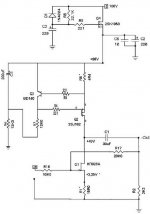
Update : OPA1656 for Output path (XLR) + OPA1692 for the preamp section
Linear PSU
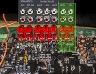
Full Balanced inputs
Unbalanced inputs
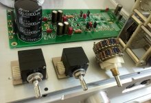
ALPS motorized volume controller
Anti RFI/RMI filter
2x120W / 8R
Full aluminium case
412 x 340 x 80 mm
8 KG
My setup :
Gustard AK4499 Dac (full balanced)
HD Audio stream source
DACS 33 floor speakers with Ribbon Tweeter 3 way
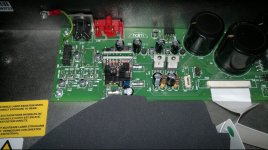
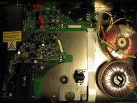
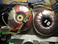
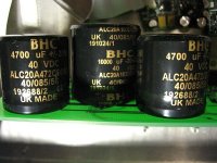
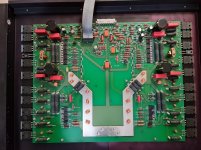
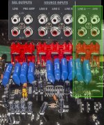
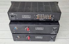
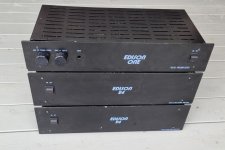
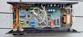
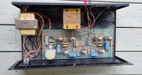
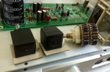
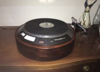
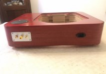
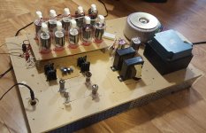
The amp already seems very well built and robust, it is quite heavy given its toroidal power supply (8KG). It is assembled in a black aluminum case and the connectors are of good quality.
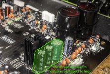
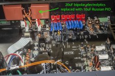
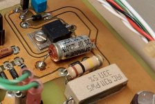
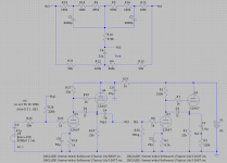
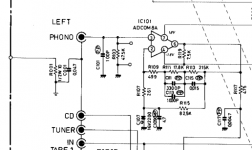
By opening the case we discover a fairly simple but very clean circuit which highlights the two Tripath chips in a dual Mono configuration, so one chip per channel. Basically it comes with two genuine OP5532 that I updated.
Everything is well made in and it's readable enough to understand that we are dealing with a well finished amp. In this price range it is also very rare to find a motorized volume controller, the amplifier comes with a small remote control.
I have a small downside concerning the automatic protection mode: indeed a chip resets the volume controller to 0 each time the amplifier is turned on.
But in the end it may be a good point to protect the speakers
The manufacturer recommends a 40-hour break-in to polarize the components; I am still far from it because I barely did ten hours of listening.
I listened to multi styles in HD Audio to see the potential of the amp and I can already tell you that the amp has enormous potential!
You have the option of bypassing the internal preamp via two small switches. (bypass preamp 0db or use preamp 12db)
I made the test with the preamp only for the moment. The OPA1692 update on the preamp section allowed me to considerably improve the soundstage and refine the highs.
Here is my feeling:
Highs :
Tripath is well known for its definition, especially at the top of the spectrum. On my jazz register, the ride "chabadas" are sublime! The hi-hat, cymbals and effect cymbals come out beautifully and the Tripath / Ribbon Tweeter combination works wonderfully.
The higher-pitched voices come out extremely well in the mix in most of the albums listened to and the amp is in no way aggressive in the treble, the listening is very musical and muffled.
Mediums :
With the OPA1656 the mids are straight and very neutral. Compared to the 5532, I found that the OPA1656 brought a lot more warmth and "naturalness" to the vocals.
Here we keep the analytical dimension of class D with the advantages of class AB.
all the voices come out wonderfully, the baritone, soprano and tenor are really well transcribed.
Bass :
I never liked amps with bass transcribed too far forward. Here the bass is balanced, fair and round as it should. in the Pop to Rock register, it's clean and it doesn't bleed.
The delicate bass acoustic articulations are reproduced very well. I refer in particular to the mix in the rhythm section double bass / drums which stands out to me in the Jazz register.
Conclusion :
I was very skeptical when I read the German forums. But I can tell you that this amp is a killer considering its price. I was able to compare it to my Dual Merus reviewed recently on ASR and even against my Purifi, this amp is probably the most "musical" of the class D that I have been able to test. It is silent, very dynamic and absolutely warm in all registers.
This amp has everything a big one, a huge soundstage, enough power to drive big speakers and above all flexible with the possibility of personalizing your sound with your favorite OP amps in DIP8 format and even the possibility to bypass the internal preamp.
I have not tested the ASR Emitter 2 highlighted on the German forum (
Kellerkind-Audioforum - "MD"- PopPulse T180) and which has been compared to this Poppulse but in my humble opinion this amp will overshadow much more expensive amps. I had the pleasure of testing a bunch of amps much much more expensive but really less efficient than this Poppulse! If you find one, go for it!
Demo Video :
In progress. Will share later
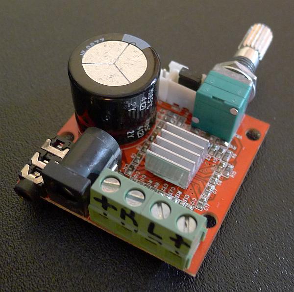
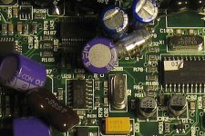
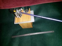
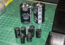
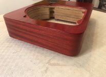
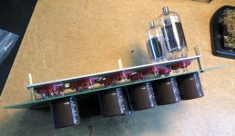
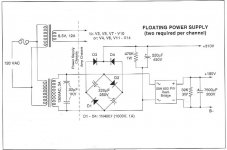
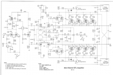
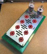
Pictures :

 envoyer des photos gratuitement par internet


 envoyer des photos gratuitement par internet
 envoyer des photos gratuitement par internet


 DSC04869
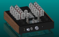


![[Real attenuation that was recorded].jpg](https://www.diyaudio.com/community/data/attachments/871/871621-d04f53c283aaec5756695a9cca49a8a2.jpg?hash=0E9TwoOq7F "[Real attenuation that was recorded].jpg")