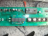
Luxman MQ68C tube substitution - potential for Screen Drive?

Hi,

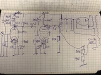
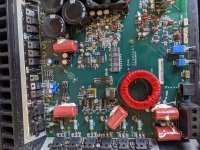
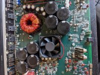
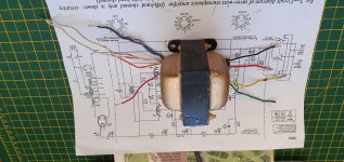
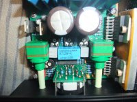
I need some input....I was gifted a Luxman MQ68C a while ago. Originally, the power tubes are the obsolete 50CA10 in triode mode push pull fixed bias with a plate voltage of 400VDC and a 6K OPT. The tube is capable of 35W in that way, Luxman rates the amp at 30W. The original tubes are long gone, and the Chinese replacements have a dubious reputation and are not inexpensive.

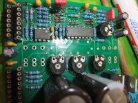
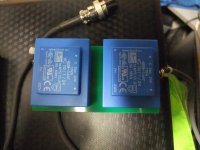
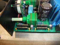
I have been putting this project off because I am not happy with the idea of running EL34 in this amp. I did install a 6A 6.3VAC transformer to power the new power tube heaters, and installed octal sockets. The PT has a 0-360V 280mA HV winding on the PT, the 50V heater will be released from duty, reducing stress on the PT.

The original EL34 would put out 19W according to the datasheet, and new production tubes would obviously be less.
The alternative is 6550 in triode PP, this does around 25W, still not at the 35W mark for the 50CA10.

The KT88 does not fit, the sides of the bottles touch. *yikes*

So then I looked at alternatives and came up with two options that I am considering:

1) KT90 biased at 50-60 mA in triode mode. The skinny bottles fit well in the amp.

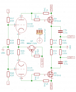
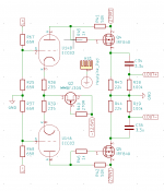
2) JJ EL509S in Enhanced Triode mode (screen driven). This way, the bias current will be about 10mA per tube and this will make the PT run much cooler. I may not have enough drive from the inverter to get enough power from this tube. But that can be fixed with a Mosfet.

Has anyone done this before, or anything similar? What are your thoughts on these approaches?

X-over realized by Laptop, Open Source and 7.1 AV Receiver over Display Port / HDMI

Good Day,

enclosed find my first Howto. Its about my setting up a X-over with a Laptop, open Source Software and one 7.1 AV-Receiver over DP / HDMI.

https://1drv.ms/b/s!AnKX4vLSHn4Nh5cTCw2UlL4DP9Ly5w

With this solution you can activate two 2 Way or 3 Way Loudspeakers without need of any additional hardware.

If any comments please feel free to contact me.

Regards
Guenter

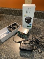
FS: Turnkey Raspberry Pi DAC Setup

IMG_0352.jpg

Here's a turnkey Raspberry Pi DAC setup - just plug it in, everything is included.

Raspberry Pi 3B+ (Retail $35)
Micro usb to barrel connector power connector (Retail $5)
MicroSD Card 16 GB with a fresh install of MoOde Audio (Retail $10)
HiFi Berry DAC + Pro - this is one of the few DAC Hats that has on dual board oscillators (Retail $53)
Misc. mounting hardware and 6061 T-6 aluminum top and bottom plates forming an enclosure (Retail $15)
iFi iPower power supply (Retail $49)

The retail value is $167 plus shipping from all the various sources. AND, this is built and ready to go.

Yours for $125 plus shipping.

Popping sound from speaker Pioneer A301 Integrated Amp

i was able to repair my Pioneer A301 integrated amp after years of slumber. The amp is working fine but when i hook up my Pioneer GR333 equalizer after an hour of music popping sound comes out from my left speaker. My equalizer has some tight sliding knobs of some of the bands which i loossen it with a contact cleaner. I checked the components afters hours of troubleshooting and they are seem to be fine. Does the sliding knobs of the bands has something to do with the popping sound? since they are stucked for a long time? Thank you in advance.

Help needed: diaphragm sticking to 1 side of stator

Hi,

I just finished building a new pair of esl's. The first days they played fined. But one channel now has problems: it's diaphragm sticks to one stator. I can lower the bias voltage to solve this problem, but this costs me 15 dB sensitivity...
Sometimes the diaphragm doesn't stick to the stator and then everything seems fine.

I have to admit that I forgot to put small (1x1 cm) spacers between diaphragm and wire stators: in my previous esl's I put these spacers in the horizontal middle, every 30 cm vertically, to reduce the effective with of the diaphragm, similar to the silicone dots used by Audiostatic. After attaching the first diaphragm I became aware that I forgot to attach these "spacer dots", so I just tested the esl and it worked fine, until today, now one channel sticks to the front stator.

I'm wondering what can be the cause and what would be a solution? My own ideas:

* diaphram too wide in relation to diaphragm - stator distance: according to a Duch book about DIY els building, a max. ratio of 1:100 should be used for diaphragm width: my d/s is 1.7 millimeters, so 1.7 * 100 = 17 cm width is max. allowed width to get good static stability. But the book suggests to be on the safe side and use 1:70 which results in 12 cm width. My diaphragm is 23 cm width. Solution: put the small 1x1 cm spacers which I forgot in the middle of the diaphragm.

* diaphrahm tension: raise tension. I think this will be difficult. I didn't put much tension as I used ducktape to tension.

* too much difference between distance of stators and diaphragm. (asymmetry)

Any advice what to do and what would be the cause? I tend to remove the diaphragm and put the extra 1x1cm "dots" vertically very 20 or 30 cm.

Power trace on top or bottom layer?

Im trying to optimize a diamond buffer module for my preamp. In doing so ive come to ponder if its a good idea to keep the power traces on bottom layer and then all signal traces on top layer, which is the opposite of the advice ive read in the past.

My thinking is that if the power traces are on the bottom then shieled by a top layer ground plane then top becomes the layer with the lesser radiated interference and thats where the signal traces should go. Please let me know if thats a sound plan 😀

FS: Behringer A500 Amps

FS: Behringer A500 Amplifier

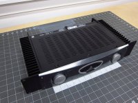
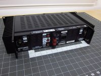
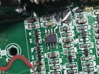
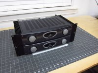
I have a Behringer A500 stereo power amplifier for sale. It is used and has had the RCA input jacks removed due to a design defect. The TRS and XLR inputs work fine. Other than the removal of the RCA input jacks and jumping the required signal-detect lines, there have been no other modifications. It is fully functional and has no issues.

Full specifications can be found here:
https://mediadl.musictribe.com/media/sys_master/hb9/h18/8850223366174.pdf

Product page:
Behringer | Product | A500

Shipping is only within the lower 48 states of the USA, will be via insured UPS Ground service and tracking will be provided upon purchase. Payment is via PayPal ONLY.

I am asking $125 SHIPPED for the amplifier.


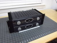
[12-Oct-2020: Disregard the fact that two amplifiers are shown in the attached pictures. I originally had two for sale, one of which has sold]

Attachments

  • Behringer_A500_power_amp.zip
    Behringer_A500_power_amp.zip
    139.9 KB · Views: 79
  • 01.jpg
    01.jpg
    129.9 KB · Views: 341
  • 02.jpg
    02.jpg
    127.4 KB · Views: 345
  • 03.jpg
    03.jpg
    87.6 KB · Views: 342
  • 04.jpg
    04.jpg
    134.3 KB · Views: 343
  • 05.jpg
    05.jpg
    129.9 KB · Views: 341

Designing my matching TABAQ center speaker

Hi all,

I built myself a pair of large TABAQ. I am satisfied with its performance. Compared them to a set of Elac Unifi 2.0 UB52, they are not far behind.

Now I am thinking to build a matching center speaker. I know 99% of center speakers are in the MTM configuration. Mid range - Tweeter - Mid range.

However I am not planning to use a tweeter as I am not verse with building x overs.

So my question is there still a benefit of having two drivers in series (two 4 Ohm full range drivers in series).
Would that be same as using one 8 Ohm full range driver?
I assume the output in terms of SPL is the same?

Is the reason of a MTM configuration is to be symmetrical putting mid range drivers on left and right of the tweeter?

Pilot 505 Amp

Some years ago I tore apart a couple of console units. One was a Pilot 505. I put new capacitors in the amp and was working on the MPX unit when I got distracted and never got back. I've just ordered JJ tubes for the amp and would like to see if it works.

What can I do for a pre-amp? I'd like to build your kit unit but haven't the time right now. Is there a reasonable priced phono unit I could use just to test this?

What kind of power does it have and what to do for speakers? The original speakers were largish but without heavy magnets and no enclosure so I'm guessing I need easy to drive speakers, correct?

(this stuff is probably in your beginner's thread, sorry.)

Anything overly bad here?

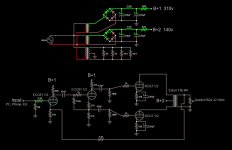
I have prototyped this on the bench and am hoping that someone with more experience than I can point out anything that I've gotten out of whack. It works fine and sounds amazing to my ear. I just don't want to build a seriously flawed design. The power supply shown in the schematic is using a toroid that I wound myself, using the original primary. I had to draw it as three transformers, but it's actually just three secondaries on the same transformer. I may or may not incorporate a filament rectifier. I'm very interested in regulated power supplies, but have only found information related to specific supplies and voltages. I don't know how to modify them to output different voltages. I'm open to some good reading material if someone can point me in the right direction.


The phase inverter bias is something that I'm particularly concerned about. I am having some trouble grasping how it works exactly. I really like the sound of the ECC81, despite it not being particularly linear. I also happen to have a few of them on hand. The preamp triodes are biased to 3.5mA and 112v plate voltage (310v B+) using a 56k plate load resistor. The 6CG7s are in push-pull and are biased to 13mA at 140v. They are driving an Edcor 12k:4R PP OPT and I am using 32 ohm Grado RS2e headphones. I am currently in the process of winding another toroid to ~450V so that I can run the ECC81 a little hotter without reducing the plate load resistor very much. I tried it with a 10k with the current power supply and it just didn't sound as good to me. The highs weren't as twinkly if that makes sense. I am considering some other preamp/phase inverter tubes as well, and would like to have the extra B+ to push them a little. Thoughts? I appreciate all the help that I've gotten here.


Edit: After posting, I realized that I had the 6cg7s running too hot. I replaced the 820R resistor in the PSU with a 1k6. That dropped the B+2 down to 120v and the 6cg7 plate current to 10.4 mA. 1.24 watts dissipation per triode now. Under the 5watt total (per tube) maximum.

Attachments

  • Audity III.JPG
    Audity III.JPG
    74.5 KB · Views: 445

Mpl

I am planning to build a loudspeaker that complements my MPP. I have build a preamp and Brianco is doing a poweramp so in the next month a system will be made of Phonoamp, Preamp, Poweramp and Speaker for DIY.
The speaker is based on a wideband unit in a baffle.
Under 80 Hz it will be complimented by a dipol woofer and over 7kHz there will be a horn loaded Ribbon.
The wideband driver got developped over a period of one year.
It has a classical paper cone and Alnico magnet.
I got the finished samples some days ago and did some measurements.
The driver is designed for very low distortion.
It is under 0.5% up to 100dB in 1m second harmonic. Thirs id under 0.1%.
Today i will post some measurements.
The driver is in a 90cm by 125cm baffle placed asymmetric due to golden cut.
I will pulish photos and drawings later.
Impedance is 6 Ohm Re and sensitivity is 96dB for 1W/ 1m.

Attachments

New Member from Horsetown

Hello,

New member from Horsetown USA (Norco CA). I've been reading the threads and now I am one. This should be fun thanks for letting me in. I have a couple of vintage systems I working on with a goal to land on the "One". I have a Hafler DH-100 paired with a Speakercraft BB275 and Wharfdale Diamond 9.1 speakers (with GR Research kit) and I have a Harman Kardon TA 5000x paired with TriTrix MTMs. I also have a couple of CD players and a Phillips 777 TT. like everyone I mix and match. I like to tinker with my stuff so almost everything I have has been restored and upgraded. If you have any questions for me about this gear please feel free to ask as I have worked on all of it.

Cheers,
Bill

Phono Pre-amp Tube setup - 12AX7 plate voltage

Hello,

I'm new but I'm going to jump right in.
I have a H-K TA5000x that I’ve been slowing restoring. The only schematic I have found is in two parts, Part 1 has the right side cut off and Part 2 has the left side cutoff, which results in the phono preamp being shown on Part 1 and the power supply on Part 2. Unfortunately, while very similar, Parts 1 and 2 are not same version of the schematic. The specific problem I have is the phono preamp plate voltage feed from the power supply (Part 2) is listed at 190vdc, which I have measured to be 188vdc. This same supply is listed on at the phono preamp in Part 1 as 270vdc, which is then reduce to 170vdc and 120vdc before going to the plates. I have measured the plate voltages to be about 120vdc and 78vdc; this seems very low as these tubes are rated up to 300vdc plate voltage. It plays okay but I think it could be better. I definitely have much lower volume from phono then the radio or Aux and this receiver seems to have a little bit of low volume in general for the watt rating. I’m currently running reissue russian TungSol 12AX7/ECC803S gold pins and I have some used mismatched vintage tubes that work but strength is unknown; there are differences but in general new and old tubes work the same. Should I adjust the power supply voltage to the plates by changing resistor values and if I do what tube performance parameter should I being trying to achieve?

TA-5000X Radio Harman Kardon; New York, build 1965 ??, 9 pic

Thanks for reading and any input is welcome.
Bill

Free to good home

I have been trying thin my collection of audio gear. I have a pair of mltl speakers I built several years ago using the mark audio ch70 drivers. I built them for a bottleneck meet competition for small drivers. These sound very nice with surprising bass. I need to move them on so they are free to a good home. I live in the dc suburbs and won’t ship them. If you want them let me know and come and pick them up.
Viet came and picked them up this morning. I hope the recipient enjoys them.

NAD 3020 series not not helpful!!

So I'm working on one of these that had blown fuses, this appears to be, not supprisingly that the 4 main output transistors were installed without insulating sleeves on the securing bolts. So all I have to do now is sort out the left chennel centre voltage. Now for the good bit, the PCB has no markings to show what resistors are what, only the caps and diodes are marked on are on the board, great!! 😱 Anyone else ever had this?

RIAA Preamp EF804 tube

Hello guys, recently finished my first Riaa preamp with ef804+El84 tubes. The first impresion when started was wow, really good sound, no hum at all and i am very happy with it. Later i have started playing with anode voltage and cathode resistor for ef804, and everytime the sound changes, sometimes it is worse, sometimes it looks better, so the question would be: does anybody in here have expierence with ef804 biasing? It looks like it low current tube, but there is si many variations to try…. Any tips would be a huge help guys, thanks.
I will also upload full schematic, so any sugestions are welcome.

Attachments

  • 40BA0F2F-B87D-4375-8B99-1DE80C91BED6.jpeg
    40BA0F2F-B87D-4375-8B99-1DE80C91BED6.jpeg
    326.8 KB · Views: 565

Wire Voltage Rating For 6V6 Amplifier

I am rebuilding a mono integrated tube amplifier that has been neglected. I will be replacing all of the capacitors, resistors and wiring. The current wiring is 20 gauge SOLID throughout. I would like to use the same because I find it easier to work with than STRANDED.

The 20 gauge SOLID wire I have is rated at 300 VOLTS, the only 600 VOLT wire I have is STRANDED.

Looking over the schematic, there appears to be only a few wires that carry more than 300 VOLTS, pin 8 of the 5Y3 rectifier to pins 4 of the 6V6's. Also 5Y3 pin 8 to pin 1 of V2 (12AX7).

Is it safe to use 300 VOLT wire for the everything else?

View attachment grommes 55pg schematic.pdf

Attachments

TSE-II 300B OPT mA rating

Beginner here, working on putting together a TSE-II 300B with a target operating point of 385v B+ @ 60mA. Jack of Electraprint is suggesting a 65mA rating for the output transformers after I'd initially mentioned wanting a 100mA, saying "all tubes rise in current when driven, it is only temporary or 70% of the peak" (sic).

Is this correct? My reasons for second-guessing this are that, first, most of the OPTs for 300B applications I see have at least a 100mA rating, and I've seen multiple references to a 100mA rating for Electraprint OPTs in particular; and second, my understanding is that in an SE amp the current through the output tubes is relatively constant, varying little with applied signal. I'm not sure quite what to make of his explanation.

How likely am I to run into saturation with OPTs rated for 65mA? Am I guaranteed to run into saturation if I were to later decide to run the tubes at 80mA?

McIntosh C22 preamp clone on Aliexpress

R5jCBuy.jpg


Seems interesting, if perhaps only an MC22 in spirit. Casework looks good enough to fit in a modern system. The input selector is relay based, and the tone stack looks accessible to change for custom breakpoint frequencies. I like that its got room for modifications, and that it's entirely tube.


The original MC22 used six tubes - five 12AX7As and one 12AT7, but it also had a phono section which would occupy several of them. I do think there is supposed to be an additional tube for the output after the tone stage.

Brand is BRZHiFi. I'm not familiar with them so I'm looking for input. More pics of the inside:
BRZHIFI AUDIO MC22 tube preamplifier high and low tone control|Amplifier| - AliExpress

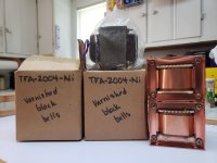
300B TFA-2004 Parafeed w/IT Drive

I have begun a new amp incorporating parafeed, transformer drive and Ultrapath. I already have all of the necessary iron and would welcome comments.

I'm not sure what size small cap I will need to lift the rectifier output from the choke input filter value of 450v to the 520v I need, and I'm not sure if I want to use 10uF or 20uF caps in the driver supply. The cathode resistors are only best guesses as well. Most of the PS caps will be CDE oil motorstarters, as well as the parafeed cap. I want to be able to switch rectification and possibly 300 cathode resistances in order to vary operating points.

I will breadboard (actually plywoodboard!) and fine tune the complete PS through the loading coils and driver transformers using power resistors to draw the necessary current. When I'm sure I have the proper currents and voltages available for the plates I'll repeat the process with tubes to get the cathode resistor values.

Doc B might get a kick out of the transformer/choke picture and the Valve magazine page with the Electronic Tonalities add for the trannies. I was a member of Valve in the late 90's and bought them from him then. $600 a pair for full nickel at the time - those are not the Pinstripes or the Juniors... The chokes are 50H/100ma units I got from Japan a decade ago. I can't remember who made them.

Attachments

MMTMM

So I've read quite a bit on here about using psuedo coaxial arrays to
help control directivity. Using delay with a DEQX Ive been toying with the

idea of making a mmtmm design. But my one preference is to use a 3/4" or smaller tweeter. WHy? Because I like the way they sound and contrary to
many people who say that they cant hear above 10khz I can tell the difference.


I used a peerless 0.5" one time over a 2 inch mid and I loved the way it sounded.


So here's my idea, Im looking for input if this would work and and tweaking ideas you all might have.


For the tweeter using the Wavecor TW013WA01 13 mm, flanked by two Morel MDM 55 followed by 2 RS125T*8 5" Reference Woofer Truncated woofers. With this configuration I can get a very tight grouping.


My crossovers would be around 1100hz and 3000hz. I can get the center to center spacing around 132mm and 322mm for the woofers!


What I'm looking for is really good imaging, nice resolute mids and highs. I dont need super deep bass or loud spl as I live in a condo. Again this would be a purely active setup ran off of a DEQX so no crossovers needed.


Thoughts???

Attachments

NGSpice compatible audio op amp.

Picked OPAx134 op amps because they have a good rep. Couldn't get them to work with KiCad/NGSpice. That's a morning I won't get back. Apparently you need NGSPcice 35 which is due for release RSN.

While poking around I read the OPAx134 doesn't like being a unity gain buffer. Since that's what I need for much of the circuit, BAD CHOICE.

Looking for recommendations for an Op Amp that, in order of priority:

- Has a great subjective sound
- Has models that work well with NGSpice
- Works well with unity gain
- Is easily available in Europe

That's the big ones. Small ones that would be handy but are not deal breakers:

- Is available in 1, 2, 4 versions
- Has the same pinouts as OPAx134
- Works well objectively, for bragging rights

Suggestions welcome. I hope the requirements are too specific for general Op Amp wars!

Unmarked TTA1943 and TTC5200 transistors?

Anyone purchased any of these unmarked transistors from EBay? and do they perform to specifications?
These transistors appear regularly on EBay by a UK based seller called "nikkoelec" which is in fact EBay trade name for Nikko Electronics Ltd, Omar Dalbani, 358 Kingston Road, Epsom, Surrey, KT19 0DT. This is virtually the same company as SWL Electronics Ltd and Dalbani Ltd.
The transistors they offer are specified as "Unmarked" and "Generic"!
As far as we know TTA and TTC transistors are a registered propriety Toshiba transistors which means that no other manufacturer can legally make any such device number. Also, it is well known that Toshiba does not make "generic" versions of their devices nor unmarked ones and all TTA and TTC devices must be laser branded and traceable.
Therefor we feel that it is imperative to bring a strong warning to all members.

FS.Electra Print Audio Co.VT2KB,300b types Pair Single Ended Output Transformers.$600

Electra-Print Audio Co.

Model VT2KB

One Pair (2 matched pieces) Single Ended Output Transformers
about 14 lbs each ( yes, very heavy duty )

$600 per matched pair

it is primary 2.7k ohm with high wattage ( high 160 MA )
Multi taps secondary from 2 ohms to 32 ohms ( color codes available )

for we300b types vacuum tubes ( yes it works with regular 300b tube with better bass )
such as ...
KR 300b 300BXLS KR 52 842 ... Vaic / emission labs VV30b VV52 520b 320b 842 1605 etc
(not limit to, depends on your application, i have tried with all those tubes about up to 30 watt output )

was removed from working amplifiers
so , they are good in working condition ,

will come with new unpainted matching end bells shielded covers
so you can install easily the way you want

with difference position bracket for your need

declaimer .. please be understood that these are amplifier parts, actual application depends on your setting and design spec, however may be able to assist after sales for best of my knowledge

my price is simply including PayPal fee, actual shipping will apply depends on your location

Local pick up welcome ,

Coupling Cap Output in Phono Preamp

I'm upgrading a nice phono preamp. It has inexpensive output coupling caps (some generic type). I'd like to play around to see if a premium or at least better than mass production inexpensive cap would improve things.

This unit has 2 30uF film caps coupling two 6922 tubes to the output to single ended RCA outs. That seems like such a massive size. Do I have some leeway in going down in capacitance? I don't like messing with a designers voicing but caps of that tolerance start getting huge when you buy better product.

Rockford Fosgate T20001BD Problems

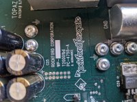
I have a Rockford Fosgate T20001 Power series amplifier, board ID PC-4755-A.

It powers own, without going into protect. As soon as it does, there is a clipped signal coming out of the output at rail voltage. It also drains the rails very quickly as soon as you power off, roughly 30 second. It makes a little screech sound when you power it back on ONLY when it has drained the rail voltage.

I can hear a slight buzzing sound coming from the output area, but I can't pinpoint it.

This is all with no audio input, RCAs are unplugged, and the amp board is still mounted into the chassis.

I did not have any shorted FETs, and the power supply gate drive looks normal (tested without 12v input, just remote and ground). Once 12v and remote are applied, it looks terrible.

Any ideas on what to check?

Attachments

  • PXL_20210722_181730630.jpg
    PXL_20210722_181730630.jpg
    815.2 KB · Views: 125
  • PXL_20210722_180847073.jpg
    PXL_20210722_180847073.jpg
    959.9 KB · Views: 148
  • PXL_20210722_181746490.jpg
    PXL_20210722_181746490.jpg
    1 MB · Views: 204
  • PXL_20210722_181758836.jpg
    PXL_20210722_181758836.jpg
    1 MB · Views: 119
  • PXL_20210722_181803616.jpg
    PXL_20210722_181803616.jpg
    1 MB · Views: 112
  • PXL_20210722_181810811.jpg
    PXL_20210722_181810811.jpg
    1,012.3 KB · Views: 87
  • PXL_20210722_181818880.jpg
    PXL_20210722_181818880.jpg
    993.1 KB · Views: 87
  • PXL_20210722_181823296.jpg
    PXL_20210722_181823296.jpg
    1 MB · Views: 95
  • PXL_20210722_181827868.jpg
    PXL_20210722_181827868.jpg
    1 MB · Views: 88

Leaving amp switch to On all the time

My amp, an Usher R1.5 consumes 55 watts when it is "off" as it retains a current even when the power switch is on the "off" position. This is to keep the amp in warmed up mode 24x7. To avoid using more electricity, what I want to do is to add an external power switch and leave the amp's power switch to ON all the time. Would there be any adverse effect when turning on the power using the external power switch while the amps switch is on the ON position?

RH84 Rev2 - suitable speakers

Hi everyone,

Does anyone have any advice or experience on building suitable speakers to go with a RH84 Rev 2 SE amplifier.
I think it will output between 3-5 watts.
I do have Fostex FE126EN in the Fostex BR design box and can partner a sub woofer with them.

However I’m interested in a 8”, 10” or 12” speaker to avoid the use of a sub woofer.

My listening space since moving is very small 3.5m x 3.5m
With Suspended wooden floors (or floorboards)

Thanks

Lee

DAC tube output stage

Hi! I am building a dac tube output stage designed by A. Ciuffoli. This design draws about 10W per channel with 270V power supply, and output impedance is lower than 60ohms. As i mentioned this is an output stage so i dont need such low output impedance. I changed power supply to 150V (because it is shunt regulated) and changed the plate resistors. The tube is at the same operating point with both power supplies (135V, 2.75mA). With 150V power consumption is about 2.5W and output impedance is 150ohms. Circuit is tested in multisim and work fine in theory. Do you think those changes are worth it? Isn't the plate resistor value too low? Any advice is appreciated. I attached 270V and 150V schematic

Attachments

  • Screenshot_1.png
    Screenshot_1.png
    25.7 KB · Views: 705
  • Screenshot_2.png
    Screenshot_2.png
    26.4 KB · Views: 514

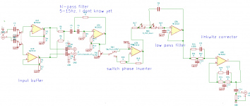
Request For Comments on my future linkwitz corrected sub

Hello, I am a total electronic newbie, I did this schematic, I wanted some comments, if I made big mistake.

I have some few questions :
- where shall I put the volume pots ? Does the resistance of the volume pot impact the opamp ?
- are the input buffer useful ?
- is this design good for phase inverter ?
- how much should the opamp be loaded ? like 10k, is 100k ok ?
- is the high-pass filter usefull ?
- should the stages be in a different order ?

The overall system will work on 24V, I'll make something to have a 12V to have a virtual mass.

Thank you very murch !

Attachments

  • schemasub.png
    schemasub.png
    23.1 KB · Views: 74

Crossover for 10” mtm

I’m posting this in response to Allen’s referencing of the speakers I’m building in another thread as an example of what can be wrong with a mtm! 😱

I'm building a $4000 speaker kit ... Which one?

Allen I’ll link the crossover for the speaker in question and maybe you can help me understand how to improve on it? Drivers are…..
https://www.eminence.com/pdf/Delta_10B.pdf

https://www.bcspeakers.com/en/products/hf-driver/1-0/8/de250.pdf

http://gpoint-audio.com/wp-content/uploads/2013/03/seos10.jpg

Attachments

  • 2EFBA2B5-6E15-4319-B90C-2F59F0B3C404.jpeg
    2EFBA2B5-6E15-4319-B90C-2F59F0B3C404.jpeg
    277.6 KB · Views: 266

Audiophile Re-cap active speakers...Which products?

Despite my total ignorance, I plan to refurbish the electronics in my old Meridian DSP5000.2 active speakers. I have a list of recommended parts to solder in place, but can't find two items:


Ansar "Supersound" caps, 3.3uF and 2.2uF 400V
UK distributors are instead selling a brand called Monacor?


Nichicon 100uF 63V caps #UFG1J101MPM which are out-of-stock


I visited Humble Homemade Hifi to learn which 400V "audiophile" caps are out there today, and now wonder if I should simply replace the Ansar with Audience Auricap XO but don't understand anything about component electronics parts compatibility for Meridian amplifier boards.


Please help a confused Newbie.

Worth a try or simply silly?

Hey folks 🙂

Not strictly a DIY query but I thought you guys are so knowledgeable as to be very well placed to answer it.

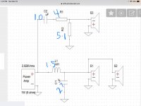
I have recently acquired a pair of Def Tech ST-L towers that have replaced Focal Domes for L/R duty in my 5.2.1 setup.
I'm currently still using a Dome as center speaker and was wondering if I could connect the other spare two with it (in my understanding, a mix of parallel and series should get me ~6ohm).
Below is a rough mockup...

triple-dome-center.jpg

Edit : Focal Dome white-paper (PDF)

What I'd hope to achieve is better dispersion, clarity (less "distortion" at higher volume?) and maybe even better/lower bass response.

The speakers have a base that can be used to fix them to a wall but I would fix them to a plinth of some kind.
They could be next to each other, separated by any amount of distance, straight inline, positioned in an arc (either inward or outward), etc etc...
They could even be vertically angled differently if it had any benefits.

Bad idea or a possible noticeable improvement to my "center channel"?

SPL GoldMike preamplifier noise

Hello guys,

Please feel free to move this thread if this is not the correct place,

I have been asked by a friend to check his SPL Goldmike preamp which he accidentally overvolted by changing the voltage settings... he blew the fuse so the overvoltage was not long, but there are issues...

Everything seems OK (voltages are correct) but there is a heap of noise and a lack of gain... I guess the temporary overvoltage did not pass through the solid state regulators (classic 7812/7912/LM317 phantom) so the low voltage circuitry should be fine, but I have some doubt about this, signal on first stage (mic preamp) seems nice enough so I think this part is OK...

It could also be the input zeners which saw a big overvoltage and are now producing more noise than input has signal, but it doesn't explain gain loss...

Would the high voltage part be damaged from the overvoltage during such a short time as a fuse blowing? It should be around 700V during a couple hundred milliseconds, would it be enough to damage the 12AX7 from the valve stage? (this is in combination with a SSM2017 or SSM2019)

I'm in the process of trying to get the schematics, found it on GroupDiy but the archive is not existing anymore and I'm waiting account activation to be able to contact the original poster...

Anyone would have some idea to point me in the right direction? The friend in question is a music artist and as anyone would guess the funds are not good these times with no events, so I'm dedicated to find a solution and help him not to spend on another preamp... (even if there is way better than this model)

Matching Transistors - Hfe or Vbe?

Hello Everyone,

Just got hold of a Peak Atlas DCA55 which is quite neat, but after running some test of the bunch of transistors I plan to use in my current project.

There are 2 sets of NPN/PNP at the output stage and I plan to use TIP41A/TIP42A and BDW93C/BDW94C.

Running the tests, the Vbe seems to be find and all well within +/-10%.
The issue is with hFE, while within the same batch they are all closed, but the hFE of NPN and PNP deviates a lot. eg. the hFE of TIP42s are approx 200 but the TIP42s are around 630; the BDW94C are about 26 and the BDW93Cs are all 37.

I did some reading on various forums and seems like matching hFE of NPN to PNP is not critical and almost impossible.

Is my understanding correct?

Comparison of 'Xbush Sphere synergy horn', versus 'Balls of Prestige'.

I thought I owed it to those involved in two of my larger builds to give a longer term review of these two speakers having lived with them for a few years, and over the last few weeks having done level matched, sighted and unsighted AB comparisons (which was hard work but fun!).
576656d1477477558-xbush-mark-2-synergy-unity-horn-spherical-proportions-img_20161026_111949.jpg

620046d1496829365-great-balls-prestige-img_20170607_104843.jpg

If you are unfamiliar with these two builds here are the threads:
The XBush Mark 2. A synergy/Unity horn of spherical proportions
Great Balls of Prestige

The differences are fairly obvious. One is a two way synergy horn with good controlled directivity, excellent measurements and using SB acoustics middle of the road (but very good) drivers. The other is a four way high output low diffraction, but more typical design using extremely high end drivers from VOLT, scanspeak and SB acoustics.

The four way system does have better than average directivity as the volt dome VM752 is horn loaded and hands over to the the scanspeak 7000 ring radiator which also has narrower directivity than a 'normal dome' almost like it is in a shallow waveguide, but it is obviously not as well controlled or tight as the synergy horn.

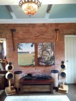
This is my newly completed listening room. The two large 'pictures' behind are 200mm fibreglass slab behind acoustic printed cloth. And you can see some of the ceiling treatments which are similar but with a 100mm gap behind to enhance low frequency absorption. I also have bass trapping in two corners to reduce some of the room modes. The room is 4mx5m with a listening distance of 2.80m. This photo is slightly 'fisheyed' and taken behind the listening position so don't worry about the apparent 'toe-in'.

Attachments

  • IMG_20181106_093720.jpg
    IMG_20181106_093720.jpg
    290.6 KB · Views: 1,400

OK for FRONT and a SIDE firing port in same Cabinet pic?

Hi I am busy making speakers as in pic but due to limited space in the design I need to put my mid range port at top of the cabinet on the side (cabinet is wider than it is deep) for adequate clearance to the rear of port.

The lower port for the bass I want to put on the front under the bass driver it won't have enough clearance to back of cabinet either but I have room there to put a 90 degree elbow in it

Is it OK to have a side and front firing port on the same cabinet?
Please ignore marks it has been altered a number of times.

IMG_20210717_094725_661.jpg

Slowly building three Baby Huey EL84 - with notes

Oh no, another Zintolo's thread about that ####### Baby Huey?
Yes. This time with building notes.

As some of you probably know, before assembling the pcbs I decided to study the project and I got bored alot of you with silly questions and pedantic arguments. I'm sorry for that, but I'm glad it helped me understanding (partially, as I'm sure I'm still missing alot) the circuit and the design process that lead there.

Everything started from Yves Monmagnon "Dissident Audio" ECL86 amp:
Push Pull ECL86/6GW8

Then it has been further developed by Ian "Gingertube" by substituing the ECL86s with a 12ax7 and two EL84 (that are equivalent to the ECL86 indeed).

Then UL has been integrated (instead of the original and preferred by Ivesm pure pentode) to reduce the THD of the EL84s, but with Hammond trafos with 43% UL taps, the ratio is not the right one (see here: http://www.oestex.com/tubes/Rudolf Moers - Appendices.pdf and here: UL for EL84. 22-24% is better than the dogma....40% is lowest distortion.... ).

Then it has been modified the CCS on the tail of the PI to increase the AC impedance and so improve the balance of the phase inverter. Total current of the CCS passed from original Yvesm value of 1 mA to 1,2 mA and no more than 1,4 mA (700 uA per side).

Then it has been applied the trick to reduce 3rd harmonic content: EL84 Amp - Baby Huey

Then the output tubes have been switched from cathode bias to fixed bias to improve the recovery when overloaded.

Then powerdrive has been applied, with a simple resistor on the mosfet.

Final developement has been to increase the driving capability of the powerdrive by applying a CCS instead of the simple resistor to load the mosfet of the Powerdrive.

About R33 and R38:
to fully drive the EL84 I need around 25 Vpp (a bit more if I want to reach AB2) up to ten times (to be conservative) the bandwidth, so 200 kHz, so slewrate will be:
2 x pi x f x V = 2 x 3,14 x 200 kHz x 25 = 31,4 V/us

One EL84 has an input capacitance of 11 pF (let's say 15 considering wiring?).

C = i x dt / V
dV/dt = 31,4 V/us

then
15 pF = i / slewrate

so
i = 15 pF x 31,4 V/us = 470 uA

The current of the CCS is 0,7 / R33 (or R38), so we'll need that resistor to be less than 1.5 kOhm. I will keep the original 390 Ohm.

Powerdrive AC voltage supply
Being the negative side of the PI's CCS connected with the negative rail of the Powerdrive circuit, the voltage is set by this one at 3 times the bias voltage ( EL34 Baby Huey Amplifier ).

So for a EL84 amp with approximately -12 Vdc it will be around -35 so, multiplying by squared root of 2, a 50 Vac winding is needed to supply it (it's called BIAS on the pcb).

About R16 and R17:
On the BOM and the PCB they are shown as 1.6 kOhm and 1 kOhm respectively, but this is due to a very early version of the Baby Huey, not the current one.
The guideline is to keep the current of the led of the PI's CCS between 2 and 5 mA, preferibly towards the lower value. In both versions, EL84 and derived EL34, R16 is around 1.5 times R17. I still don't know why, but I'll keep this proportion.
So considering the small losses in D5&R28 plus the drop due to the led, we have around -33 Vdc to be dropped by R16 and R17 with around 2 mA.
Then R16 + R17 becomes 33 Vdc / 2 mA = 16.5 kOhm. Then I decided to have R16 = 10 kOhm and R17 = 5.6 kOhm. This leads to around 2.1 mA.

About R3 and R4:
On the BOM and the PCB they are shown as 1 kOhm, but this is quite low as a value.
The old guidelines for triodes were to use 8/gm to set the grid stopper value, so with a 12AX7 which gm is 1.6 mA/V the value would be around 5 kOhm. In my guitar amps I always use at least 10 kOhm because gm of the tubes goes down with age, and I want to be sure there are no issues even when tubes are almost gone.
With an avarage value of 12AX7's input capacitance (Miller included) in the order of 150 pF, 10 kOhm gives a low pass filter with -3db point at 106.1 kHz. I would say it's plenty acceptable.
IMPORTANT NOTE: carbon comp here is the best choice, because they are the resistors with lowest capacitance and inductance, and that is what is needed in this position. I used carbon film, the second place in the choice.

About R7 and R8:
In the BOM they are 600 mW resistors, but they need to be 1 or 2 Watts, because of the voltage they see across them (remember that they are connected to the shunt feedback system that is directly connected to the primary of the output transformer.
Of course I noticed it only after I soldered all resistors, so by now I decided to install 2W metal oxide resistors on a pair of pcbs and keep the BOM ones on the other two pairs, in order to be able to check the differences.
On my experience with guitar amps, higher wattage on plates of preamps gives more dynamics and more definition to the sound (over there there's need to get higher THDs with specific harmonics), I'm curious to see if it applies to this scenario too.

About R14 and R15:
On the pcb they are shown as 270 Ohm, on the forum someone suggested to raise that value to 1 kOhm to be on the safe side. I'll start with 270 Ohm (originally gingertube used 33 Ohm) and I'll see how it will react. I would say that this value depends also on the working conditions of the tubes: with pentodes they must be higher (because screens have higher potential than anodes, so secondary emission is higher), then optimal 23% UL is in between, and 43% distributed load will need them lower. I'll use 23% UL connections and 270 Ohm by now.

About R20 and R21:
They are shown as 470 kOhm on the pcb, but I used 1 MOhm instead.
The reason is these resistors are part of the load seen by the PI (detailed description here: EL84 Amp - Baby Huey even if it refers to the old schematic without powerdrive), and even if the difference between 470 kOhm and 1 MOhm when in parallel with 64 kOhm is small, why make it worst?
I think the 470 kOhm value comes from the pre-Powerdrive indications, because that was the grid-leak maximum allowed resistor for EL84. Now it is no more, so 1 MOhm is better.

About C1 C2 and C5:
Here the value shown on the pcb is 220 nF. For C5 I remember it's the 1/100 rule based on the main power supply cap, so C6 in this case.
As for C1 and C2, this value is very high. I used 100 nF for all three because the coupling caps with 1 MOhm load will have an high pass filter with -3dB point at 1.6 Hz, so one order of magnitude lower than what can be heard.
I used the suggested Vishay Ero 1813 because I already used them for my guitar amps and I liked them, then I've seen some suggesting them for Hi-Fi as well, so before investing 10 € for a cap, I give them a try.
Suggestion on it?

In attachment you can see the boards with the standard R7 and R8 resistors, and with the 2W metal oxide ones.
Attachments

  • IMG_2978[1].jpg
    IMG_2978[1].jpg
    1.1 MB · Views: 764

build a 3-way bookshelf or purchase a two way bookshelf?

Hello,Guys🙂

I am a newbie to diy audio. I started my audio life last year. I purchased a pair of W3-1878 to build my first speakers and asked my father to build a amp for me. He built a JLH 1969 int. amp for me and I started to enjoy my music. I built up a raspberry pi streamer with 9038dac hat and picoreplayer for tidal. It is a good experience to me to enjoy the music. However, I have heard another system this few week and it is surprising me. I heard a same song which is a Japanese female vocal but it was more balance and more low frequency compared with my system. Thus, I want to upgrade my system. In my limited budget, I would like to upgrade my speaker first and there are two ideas.

First, I would like to purchase another pair of speaker. My budget is around HKD 3000 and I am looking for a 2nd hand speaker in Hong Kong. I found the monitor audio gold MA700 mkII and Tannoy oxford on the 2nd hand market which are closed to my budget but I had no experience to these two. In the meanwhile, Tannoy is too large for my limited area.

Thus, my second idea is to upgrade my speaker into a 3-way bookshelf speaker. I would like to use my w3-1878 as mid-range driver and purchase another tweeters and woofers. In my view, 5” woofer is the max. size of my home.

Therefore, which option is better? If I build a new 3-way speaker, which tweeter and woofer are the highest C/P for me? Thank you so much.

A write-up with links to different versions of impedance buffer and amplifiers for pi

The problem with piezo guitar pickups and piezoelectric crystals is that they are not well matched to typical audio inputs. By their nature they can generate a lot of signal, but they cannot drive a 50 kilohm typical line input. The pickup needs to work into a much higher impedance, typically 1 megohm or so.

So what to people do? They go and plug a piezoelectric disks output directly into the line input of their recorder, typical impedance 50k, or the plug-in-power mic input of their recorder, typical impedance about 7k, and they start to bitch and moan that this damn thing sounds tinny. Which is does ! But they don't understand why!

The reason why these devices often sound tinny is because the piezo sensor presents its signal through a series capacitance which is small, typically 15nF or less. When wired to a normal 50 kilohm line input this forms a high-pass filter, which eliminates the bass.

One of these can be used for a reverb plate, listening to the insides of a engine,recording the sound of vibrating things.

Mechanics may even use one of these to discover trouble with bearings or other mechanisms not easily opened or stopped.
That includes engine Knocking (also knock, detonation, spark knock, pinging or pinking) in spark ignition internal combustion engines.

They should also work nice with hydrophones. PZT-5H tubes is best for that.
In case of a hydrophone it's possible to have the hydrophone attached with a long cable and the amplifier/buffer circuit close to the piezoelectric elements.
It's of course extremely important that the circuit board and connections are absolutely waterproof.

Commercial ones uses kerosene oil, so olive oil or sunflower oil is a great alternative as it will not pollute the environment if any leaks occurs.
Plant based oils is actually possible to use in high voltage transformers:
https://pdfs.semanticscholar.org/56b6/36870fac68b1bb6e343eee914002195b8a61.pdf

All PCB boards and components are easy to solder, one just needs basic skills and knowledge of the right direction to put in the diodes.

Some PCB boards has SMD components, but Aisler and other companies offers SMD assembly.

There may be components that has lower self noise,better common mode noise rejection and so on, -but finding the best choice of components that handles from 0 to 48 volts DC power, uses maximum 10 milliamperes total, minimum self noise, has 8 pins DIP package is not a easy task!

If you know components that is superior in regard to the intended voltage range, please fork the GitHub page and make the changes you want.

PCB board for 48 volts phantom power, with balanced input and output using op amps, gain set with two resistors. It's the easiest to solder because it has no SMD components:
GitHub - Supermagnum/double-gain: A small PCB that uses two TL082BCP op amps to amplify a signal from a contact microphone.

With switches to set the gain:
GitHub - Supermagnum/double-dip: A small PCB that uses two TL082BCP op amps to amplify a signal from a contact microphone.

SMD version, gain set with switches:
GitHub - Supermagnum/balanced-smd: A small PCB that uses two TL082CDE4 op amps to amplify a signal from a contact microphone.

PCB board using ultra low self noise components, balanced input and output, 48 volt phantom power. It's a little harder to solder, because some of the solder points are quite close together:
GitHub - Supermagnum/piezo-balanced: A small board that uses a LSK389B, for preamplification and impedance matching of two piezo electric crystals. It has balanced input and output.

PCB board for 9V battery, mono audio out and single input. Easy to solder:
https://github.com/Supermagnum/piezo-9v

48 volt phantom power supply with mono headphone output. Has one SMD component:
https://github.com/Supermagnum/48power

All these links has links to Aisler, that offers PCB boards and components:
Just register and import the
PCB and part list.

Made with: http://www.kicad.org/

KiCad uses an integrated environment for all of the stages of the design process: Schematic capture, PCB layout, Gerber file generation/visualization, and library editing.

KiCad is a cross-platform program, and of curse free!

An unscientific frequency test of Yamaha DBR10 in REW

Hi all, I picked up 2 Yamaha DBR10s to make a small PA for my mom and her acoustic performances, as well as to have something for jam nights, my helix, etc. I love the size and price of the DBR10s, but Im not too crazy with how they sound. I think I should have tried the QSC cp8 before buying these... But they're hard to find these days! I decided to test them outside in the backyard with my UMIK-1 and REW. I realize this isn't very scientific, but it gave me a decent idea of what they're doing.

The orange line is averaged from 5 tests, on the ground, on it's side, in monitor mode, and the hpf is set to 120hz. Red is the same but the hpf is set to 100hz. Blue is the same but the hpf is off. Green line is the same but no hpf and the speaker's DSP was set to off.

AM-JKLXMwVTTbfMxrehXeDoiHAL7l9L8-9JJmGLdlhkIAcmfEcS_Xy8qT4HCmHCfq6g8dBp5iPhTFjur1DQlZB5VWS6x1DAHZZwAut4vXKYa-bkpiXTfMnfj2EPcsmRDmT9tT_5fP_iu1V23GA4M75c9wcFj=w2418-h1470-no


This is the speaker about 7' off the ground and about 7' away from the nearest wall... so I assume anything below around 180hz will be screwy if we're just testing the actual speaker. But I still think this info is useful since there will always be walls/ground where ill be using these!

AM-JKLWtb4uYWGlL9oB-aPr2tj2CHK-JBH1sN9i6BaJ7_MzvRccz0kASOcBy6nksZJ1L_OaB61PGVRLbLEEs_T1RFbhD9uggF-D_0OqZGvW1VUYyb3Nc4kiLRa5oHhlNOMSHkbGdYadrHb5AMHvFqEMDeh6l=w2604-h1578-no


I think it's kind of neat that my tests are pretty spot on to what Yamaha published:

AM-JKLXpamlWb_bTz0vC27brH0QIo4W9UXiYxhkmHtglAqDnYEKPXeejRiKNcxYRHTuku9bV_Xcpal4H18WxeKSWZQsso1kqlCM3iNtSazXhbdXAPgI9urXgHhuxcg0FlEHA2dLciWJoZq7L4BnDBNJkca6M=w1932-h1450-no


Well it was a fun experiment. Hopefully someone finds it interesting/useful. I definitely had to EQ A LOT of lower mids out and boost some highs. I can see why I've seen a lot of complaints that this speaker can be muddy. Cheers

FS: JVC EX-1A receiver, NO SPEAKERS

FS: JVC EX-1A receiver, NO SPEAKERS: $80 (SOLD)

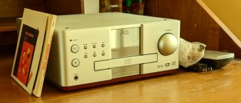
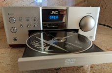
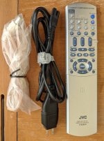
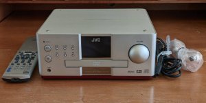
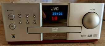
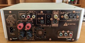
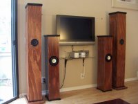
JVC EX-A1, near mint. No speakers. I am the original owner. Hardly used but when played I used my custom-made fullrange-speakers (last picture). Plays audio CDs and DVD movies (no HDMI). Comes with the original remote, power cord, and FM antenna. As can be seen the unit is near mint, and everything works as expected. Will ship within US only, please add shipping wt 15lbs. From zip: 92101 to your address.

Attachments

  • 00o0o_1JhoSqPYbKMz_0CI0gC_1200x900.jpg
    00o0o_1JhoSqPYbKMz_0CI0gC_1200x900.jpg
    65.1 KB · Views: 191
  • 00d0d_d8aL4yT71t7z_0CI0pt_1200x900.jpg
    00d0d_d8aL4yT71t7z_0CI0pt_1200x900.jpg
    78.3 KB · Views: 189
  • 00f0f_8vfWiNW0IEKz_0lD0t2_1200x900.jpg
    00f0f_8vfWiNW0IEKz_0lD0t2_1200x900.jpg
    82 KB · Views: 197
  • 00k0k_h1aCIMIRLXSz_0CI0jq_1200x900.jpg
    00k0k_h1aCIMIRLXSz_0CI0jq_1200x900.jpg
    63.8 KB · Views: 197
  • 00r0r_4S8MDI2AdjDz_0CI0h4_1200x900.jpg
    00r0r_4S8MDI2AdjDz_0CI0h4_1200x900.jpg
    54.8 KB · Views: 194
  • 00X0X_5mYw45L88bPz_0CI0t2_1200x900.jpg
    00X0X_5mYw45L88bPz_0CI0t2_1200x900.jpg
    94.8 KB · Views: 105
  • 00909_f6naMqMq0VHz_0CI0js_1200x900.jpg
    00909_f6naMqMq0VHz_0CI0js_1200x900.jpg
    97.3 KB · Views: 128
  • 00l0l_l2ZNiZ2wLa2z_0x20oM_1200x900.jpg
    00l0l_l2ZNiZ2wLa2z_0x20oM_1200x900.jpg
    81.2 KB · Views: 126

Help wiring Sowter secondaries

I've got a pair of custom Sowter's for a Baby Huey EL84 build.

I didn't get a spec sheet, but this one looks fairly the same:
https://www.sowter.co.uk/colours/8378.pdf

There are 8 secondary wires, red/blue pairs numbered 1-4.
I'm having trouble understanding how to wire these given the drawing above.

The 1ohm and 16ohm diagrams are less relevant for me.
Ideally, I'd like both 4 and 8 ohm options, so either:
* Wire in parallel with multiple binding posts
* Or switchable via toggle switch.

Thanks for your help.

Attachments

  • 2021-03-20 13.29.54.jpg
    2021-03-20 13.29.54.jpg
    231.5 KB · Views: 204

Op Amp Advice – RQ970BX Phono Preamp Andy Grove Mod

Op Amp Advice – RQ970BX Phono Preamp Andy Grove Mod

Hi
I recently bought a Rotel RQ970BX phono preamp. I wish to try an upgrade of the Rotel based on the "Andy Grove Modification" which was printed in the Nov 1994 edition of HiFI World. Please bear with me as, although I am an engineer, I have a very rudimentary understanding of electronics. I can read a basic circuit diagram and can wield a soldering iron but I am very much a “monkey see, monkey do” hifi enthusiast.

I need help with the substitution of the op-amps. The mod called for replacement of the NE5534 op-amps and replace them with the AD744’s being used in the front end. The gaps left by the AD744’s were to be filled with AD743’s.

There is still a live link to the mods on:

https://www.hifisentralen.no/forume...w_nov_94.pdf&usg=AOvVaw3AeXdNNih-x87CkDBkt1ym

There are also handy discussions of the mods below which have helped my understanding of audio circuits:

Rotel RQ970BX phono preamp mods? | Audiokarma Home Audio Stereo Discussion Forums

Dumb op-amp question from complete newbie

I would still be able to use the AD744 but I believe the AD743 are expensive and hard to come by. Op-amp tech has also moved on. On another discussion OPA627’s (output) and LME49710’s (input) were also successfully used. I have researched some alternatives and the OPA627’s successor (which are eye-wateringly expensive) is the OPA828 but its specs are quite different eg
slew rate – OPA627 is 55: OPA828 is 150
GBW – OPA 627 is 16MHz: OPA828 is 45MHz etc.
I am way out of my depth here as I have almost no idea what would be appropriate. What characteristics are important and what should I be looking for?
I would like some advice on what op-amps I could use in the circuit that aren’t too expensive or do I bite the bullet and order original. I will be putting in DIP sockets so I can test alternatives. HELP please!!!

How to create an UPS proforma invoice

I have sent a package containing a wooden amplifier case and an amplifier DIY-kit, consisting of PCBs, capacitors, transistors, ...
to a DIY-friend (chiily) in the UK.
I have created the UPS label delivery via UPS Online services.

Today I have received back the package.
Reason: I did not include an invoice, but this is needed, since the UK does no longer belong to the EU.
I did not know, when I filled the delivery sheet and the UPS shop, where I took the package, did no tell me either.

Can anybody assist me creating a pro-forma invoice for the UPS package?

Thank you - Rudi

A 44 year build of The Mullard Seven -watt Stereophonic Amplifier.

The year 1968, I was just 18 years old when I started the construction of the Mullard Seven -watt Stereophonic Amplifier. With limited funds and other distractions that grabbed the attentions of an 18 plus year old, the construction was very slow. Marriage, children and building a home further added to the delays in the build progress. During the mid-1970’s an attempt was made to complete the project. Gathering all the items together after 7 years on one work table was a challenge but at last, I was able to slowly power up the amplifier section by section. All appeared well until the ECL 82 output stage was connected to the power supply. At this point I was confronted with massive instability. This came in the form of motor boating which started within 15 seconds of power switch on. After a lengthy period of checking and rechecking some of which resulted in an almost complete rebuild centring around the tag board provided no resolution. The obvious areas were checked such as the phasing of the feedback loop but all seemed correct. The amplifier was again boxed and put into storage for some 43 years. During 2020 the amplifier was taken out of storage with the intention of finally identifying the problems. All electrolytic’s were replaced, a selection of critical resistors were replaced and all coupling capacitors were upgrade to audio grade versions. No success. Output stage still remained unstable on both channels.

At this point I made up my mind to dispose of the project and in June of 2021, plans were made to place it on eBay. While photographing it, I concentrated on the wiring from the tag board and there I thought I saw a possible cause of the problem.

Although the passage of time is long, I vaguely remember receiving the Main Transformer and Output Transformers. Where these items were obtained from has been lost but I do remember that the Main Transformer came with complete wiring identification but the Output Transformer came with nothing. As an inexperienced young person, I did not consider requesting information from the supplier. I attempted to identify the primary and secondary winding by visual inspection and taking resistance measurements. As a result, I came to the conclusion that the

• Red and Black wires (13 ohms) were the secondary winding with the yellow and green as the centre tap.
• Red & Orange anode (1056 ohms), Blue and grey 20% feedback and white as centre tap of the primary

It was with these identifications that the construction was built way back 44 years ago. I now question whether this identification was correct?
If I was wrong, then it is likely that I have used the primary winding as the speaker output while the Secondary connection were connected to the anodes of the ECL82’s using the Blue & Grey connection as the 20% taps.
Have I got it wrong? If yes then the supplier supplied an output transformer without any 20% taps on the primary and the additional wires Blue and grey are simply different speaker impedance outputs.

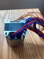
Attached is an image of one of the transformers, is anyone able to offer advice.

Before I consider moving on, I would be very grateful for any comments regarding my identification of the wiring that took place some 44 years ago

Attachments

  • 20210720_093617.jpg
    20210720_093617.jpg
    875.3 KB · Views: 378

Tannoy 8" dual concentric

Hello y'all! I am hoping somebody out there can shed some light. I bought a pair of CMS8s (8" driver) and put them (& crossover) into floor-standing cabinets (Phase Tech 7T). But - something is not right with the sound. I can't put my finger on it but it kinda sounds like there's a large tube in front of the driver. Like the midrange (1 KHz?) is bumped up maybe? It's quickly apparent when switching from a Thiel CS2. I previously put a CMS6 into a ported bookshelf box and didn't notice this problem. I tried each channel individually, and at low volume as well. Tannoy uses different size wire lugs so I'm sure the phase is correct, and I compared a photo I took of the CMS6. I traced the crossover wiring & components, comparing it to a System 800 schematic. Seems identical except for the smaller cap/larger series resistor for the tweeter used in the System 800 (higher crossover frequency?). The 800 uses 2.2uF / 4.7 Ohm; the CMS uses 3.3uF / 2.7 Ohm. Thanks a bunch.

I/V conversion circuit - noise considerations

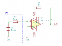
I'm currently in the process of choosing opamps to try in our I/V circuit for an ES9038Q2M in mono mode. My gut tells me that for most of the opamps that are on my list, noise will be of no concern, but let's see if I got my numbers right.

For the following calculations please see attached schematic.

So the noise contribution of the circuit shown are as follows:
- input voltage noise from the opamp
- input current noise from the opamp
- resistor noise

Regarding input voltage and current noise I assume that the noise gain of the I/V converter is 1 - ist that correct? otherwise my calculations will fall apart before they even began...

So let's add things up in an example - I'll use the OPA1611 as it's widely used for that purpose. Let's assume an I/V resistor of 500 ohms and the DAC has an output impedance of 774 ohms

current noise:
The datasheet shows a input current noise density of 2.8pA/sqrt(Hz). That corresponds to 396pA RMS noise current in the range of 20Hz-20kHz. As far as I can see Rdac and Rf are parallel in this case (299ohms) and this will yield a RMS noise voltage of 0.12uV

voltage noise:
Voltage noise densitiy is given as 1.7nV/sqrt(Hz) which calculates to a RMS noise voltage of 0.24uV in the range of 20Hz to 20kHz

resistor noise:
According to Sengpiel's noise calculator a 500 ohms resistor has a RMS noise voltage of 0.4uV in the ususal audio frequency range

Adding these up (taking the square root of the sum of the squared components) gives me 0.48uV RMS noise contributed by the opamp and the resistor, resulting in a 138.4dB SNR for a 4V RMS reference level.

I'd be very thankful if somebody would take the time look over my calculations as I have no formal education in this field and every bit of wisdom used was extracted from the internets 🙂

IF all that is correct I deem the noise contribution of a modern opamp to be almost neglible compared to resistor noise and most likely noise from the DAC itself.

Attachments

  • IV.png
    IV.png
    5.1 KB · Views: 439

Improving the capacitance multiplier

In my continuing quest to do things slightly differently to everyone else, I've come up with some ideas to improve on the capacitance multiplier. I'm developing it to use with the horn subwoofer I'm planning, which being very efficient will want the lowest possible ripple to keep hum down. I've rejected the idea of a normal voltage regulator on the grounds that they are boring.

The improvements were inspired by R.G's thread on amp output protection where he mentioned using P-channel MOSFETs on the positive rail as switches. This made me realize that the same idea could be applied to a capacitance multiplier to lower the dropout voltage (NPN BJTs need a couple of volts; N-channel MOSFETs need even more), further improving what is already one of the main benefits of capacitance multipliers.

The extra drive circuitry necessary to accomplish this also has the benefit of increasing the effective multiplier due to high input impedance. This allows the use of a smaller 'base' capacitor (what was the base capactor anyway - it's not connected to a base now); small enough to make a film cap possible here. Base capacitors can of course still be large for ridiculously low ripple, but it will then take quite a while for the output to ramp up to full potential.

Using low on-resistance MOSFETs, such as IRF5305/IRLZ34N, dropout voltage can be really very low. As low as 0.1V is possible, but more is needed if very high currents are required. This means vanishingly small power disipation, which is nice.

With appropriate component choice this circuit should be able to provide tens of amps with only mV of ripple and very relaxed heatsink requirements. Regulation is not good, but that's because it's not a regulator. It's a bit more complicated than the standard design, but still has a reasonable component count.

Attachments

  • capacitancemultiplier.png
    capacitancemultiplier.png
    5.4 KB · Views: 7,000
  • Like
Reactions: Uunderhill

DIY standmount with waveguide

I can't find many designs for standmount speakers with waveguide tweeters.
Most of the ones I find use discontinued waveguides or ones that require modifications with a router table or such. A tweeter with a built-in waveguide would be ideal or at least a still available commercial option that needs minimal modification.

Does anyone have recommendations for sub $1000, 8 ohm, 87+dB standmount speaker plans with waveguide, that would work well 1-2 feet from the wall in a medium sized room.

The Hamlet is tempting but I'd prefer US sourced parts since overseas delivery can be such a pain now.

The ER18DXT is one of the few I can find as an option.

- I also forgot to mention, the simpler the build the better. I only have a circular saw and a router. With time and patience I can build a really good box but complex internal supports or external shapes are a bit much.

SOTA 11R build

Here are some pics of my build and my recent experience with this driver. The SOTA 11R is a fullranger from Markaudio with a diameter of ~ 110 mm. I picked up a pair of the raw drivers along with some diy folks for a nice price from a dealer looking to blow out his inventory. We couldn't get any TS parameters or raw measurements from the dealer and were only told that they were similar to the Pluvia 11 drivers. So I took him at his word and built a CGR designed for the Pluvia 11 designed by Planet 10. The SOTA 11Rs look like they are built to a high standard and come with a sturdy stamped steel frame. I ran the drivers for about 20 hours in free air before mounting them in the new enclosures.

I wanted to try one of Markaudios larger drivers and was hoping for a smallish set of fullrangers that could be as nice as the old Dayton budget bookshelf speakers designed by Wayne Jaesche that I had built about 20 years ago, the cost of the two builds is about the same. Unfortunately so far this has not been the case. The CGR enclosure seems to be doing its job well enough and delivers some punchy but not deep bass, after all it is a small enclosure. My disappointment so far is with the drivers apparent lack of detail and its uneven frequency response. With some decent electronics (aleph J, aikido pre) the budget 2 ways sound pretty impressive, on the same system The SOTA 11Rs are clearly lacking. I'm going to let them run in for a few days and then experiment with some BSC filters to see if I can improve the sound.

Attachments

  • driver polarity.jpg
    driver polarity.jpg
    602.2 KB · Views: 317
  • lined.jpg
    lined.jpg
    634.5 KB · Views: 305
  • driver fit.jpg
    driver fit.jpg
    549 KB · Views: 301
  • CGR complete.jpg
    CGR complete.jpg
    561.6 KB · Views: 303

Homebrew Motor Control Linn LP12 - Circuit Description wanted for Sine Wave Osc.

From a friend I got for repair a diy motor control for Linn's LP-12.
Compared to the X-tal versions with divider from Linn model "Valhalla" and "Lingo" is here a sine wave generator in use - similar to Linn's AXIS motor control - go to
http://www.turntablepsu.com/images/Axis Schematic.pdf
In the attachment you will find the schematics, which I have drawn out.
Who can give a description, how the circuit of the sine wave generator works or can give an advice, whether this circuit was based on an existing commercial product.
Thank you very much therefore.

P.S.: The reason for not correct working condition you will find in the fifth image.

Go to post #16 for news and new schematic, which I have drawn out.

Attachments

  • DSCF5318.jpg
    DSCF5318.jpg
    853.7 KB · Views: 1,157
  • DSCF5324.jpg
    DSCF5324.jpg
    532.3 KB · Views: 1,029
  • DSCF5322.jpg
    DSCF5322.jpg
    988.6 KB · Views: 964
  • DSCF5315.jpg
    DSCF5315.jpg
    768.8 KB · Views: 904
  • DSCF5230.jpg
    DSCF5230.jpg
    1 MB · Views: 884
  • DSCF5207.jpg
    DSCF5207.jpg
    985.6 KB · Views: 507
  • DSCF5209.jpg
    DSCF5209.jpg
    1,008.5 KB · Views: 453
  • DSCF5208.jpg
    DSCF5208.jpg
    1,008.9 KB · Views: 460
  • DSCF5240.jpg
    DSCF5240.jpg
    1,010.4 KB · Views: 452
  • DSCF5249.jpg
    DSCF5249.jpg
    1,005.1 KB · Views: 531

Noob here: criticise my Ncore-based amp design please?

Please forgive me if any of this is stupid or ignorant.

A home burglary has put me in the position to assemble a HiFi system from scratch, and after looking at the available amplifier options I thought "why not make one myself?
I have some half-decent soldering skills and enough knowledge to get me into trouble, but no experience with building audio devices, so I'm hoping someone will point out any glaring errors I've made.

I don't know yet what speakers I will pair with this, though I liked my old Paradigm 3SE's. I figure once it's built I can take to to my local HiFi store and they'll let me audition some speakers with it.

Here's my terrible photoshop layout. The red rectangles are to scale with the given internal footprint of the case.

vR6Fp4u.jpg


My parts list (in $AUD) is:

Ncore NC122MP 4Ω-125w/ch 8Ω-75w/ch $544 85x170x40mm
(probably shucked from Audiophonics build if I can't find the module by itself)

KHADAS Tone Board $135 82x75x25mm

Relay volume control $140 100x65mm
Is this unnecessary overkill?

Case $45 w182xD200x48mm 8mm front plate
Or vented version

I intend to replace the side panels with some lovely Redgum and countersink the volume knob into the aluminium faceplate. These are things well within my skillset. I like the compact size TypeD will allow and I'd like for it to have a sleek, minimalist look.

Questions:
Is there any reason I can't desolder the RCA outputs on the DAC and solder cable in place to send the signal straight over to the volume module?
What cable should I use (in general) and are there any hints for routing to reduce noise or the like?

I guess they need to be twisted?

Is 60/40 cored resin solder okay or do I need something special?
Any suggested options for adding a sub-out?
Am I cutting it too close with the size of this case? Should I be going slightly larger?
Is there anything I've missed?
I truly appreciate any input.

Tactile Switch for Micromega Model "SOLO" and "DUO" first Series

In the attached pictures you will find the wanted switches.
Who know the manufacturer (Made in France) ?
Maybe the brand COSMOS are replacements:
https://datasheet.octopart.com/81-10101-00-EAO-Switch-datasheet-8497360.pdf
https://download.siliconexpert.com/pdfs/2006/09/29/c/cs/eao/ds/cosmos key switches.pdf?
But I don't know exactly
Thanks for an advice.

Attachments

  • DSCF7325.jpg
    DSCF7325.jpg
    789.8 KB · Views: 195
  • DSCF7326.jpg
    DSCF7326.jpg
    715.4 KB · Views: 143
  • DSCF7327.jpg
    DSCF7327.jpg
    695.4 KB · Views: 156
  • DSCF7328.jpg
    DSCF7328.jpg
    679.7 KB · Views: 161
  • DSCF7310.jpg
    DSCF7310.jpg
    1,022.4 KB · Views: 198

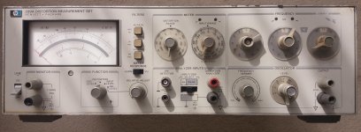
HP 339A set

Purchase via EBAY a Distortion measurement set HP 339A from an supplier from Israel. This morning it arrived an I did some quick tests. It is a good functional set and I am now very happy with it to test the THD of my tube amp designes. Oh yes, the Forum will shout to me " but there are very good software tools to do that job" and, yes, I agree. But anyway I am glad to have a set that will do that job also.
Here a picture of my set:

Attachments

  • HP339ARes1.jpg
    HP339ARes1.jpg
    318.2 KB · Views: 163

Daphile wont boot with Intel NUC

I just received a used new 2017 Intel NUC7PJYH (with an optic sound port 1/8).

-I try to swap my Daphile already installed and working HD in the NUC. I received a error message : no device bootable. I set the Bios in different way, with Linux setting without automatic on graphic..., I reset to default, nothing to do. I can boot with this HD a Lenovo micro and a old Dell ATG.

- I reinstalled fresh the last version of Daphile, nothing change, always the same error message.

-I try to install Linux Mint cinnamon v. 18 and the NUC was working very well. I booted also from my USB key.

Regards,

Jean
Projects by fanatics, for fanatics
Get answers and advice for everyone wanting to learn the art of audio.
Join the Community
507,672
Members
7,883,590
Messages

Filter

Forum Statistics

Threads
405,997
Messages
7,883,590
Members
507,672
Latest member
rooomn