OPS asymmetry

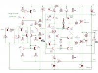
I am modeling an amplifier with Multisim using an EF3 OPS with 6 pairs of MJL3281A/MJL1302A driven by MJE15032/MJE15033.
With a 1KHz input signal and an output voltage of 34.6VRMS into a 4 ohm load (300WRMS), the Fourier analysis of the output node shows a THD of less than 0.0001% (9 harmonics) so the closed loop behavior seems OK.

I do a Fourier analysis of the VAS (the test node is the connection of the VAS collector to the bias spreader) to get an idea of the "correction" applied to the OPS.

With 0.2R emitter resistors, the VAS THD is 0.054% with a dominant 2nd harmonic (0.026%).

Changing the emitter resistors *only* on the PNP output devices (MJL1032A) to 0.26R (empirically determined) lowers the VAS THD substantially to 0.011%, now with a very low second harmonic. (<0.0002% = much better symmetry)

The bias is set for best THD (approx. 70mA).

I thought that something may be wrong with the models but I also tried MJL21194/MJL21193 with similar results.
Looking at the data sheets, I see that these PNP devices tend to have a higher current gain which seems to explain this.

Your thoughts and/or experiences please.

[POWER AMP] Hypex NC502MP full balanced 2x350W / 8R, free shipment Europe

Hi,

I selll a brand new Power amp based on the Hypex NC502MP module.
Everything is mounted with a great care
2x350/ 8 ohms
Full balanced inputs + Audio grade Filter module
Push Banana Plugs
Full alu case

Paypal Only
Free shipment to Europe only please.


Price : 550 euros


Hypex NCore NC502MP twin Channel Module
Full alu case / Sommer German cables
PSU SMPS integradted 1500W
XLR inputs full balanced
Auto sensing 100-240V mains input operation
0.5W standby operation
1.5KW Main PSU
47K Ohms Input Impedance, low output impedance
THD 0.0018%
S/N Ratio 116dB
26dB Voltage Gain
2 x 350W 8 Ohms


en majuscule

Tutorial: Raspberry Pi as Music Server, DSP, and Crossover

Hi DIYers,
I thought I'd share a little project I've put together for Pi Day! I made a music server, DSP, crossover on the Raspberry Pi 2 using native ALSA hosted LADSPA plugins using Charlie Laub's ACD-L plugins.

Check it out and let me know what you think. I'd also love for you to vote for my instructable in the the Raspberry Pi contests. 🙂

http://www.instructables.com/id/Raspberry-Pi-Music-Server-With-Built-in-Crossover-/

I have to also shout out a big thanks to Richard Taylor, Charlie Laub, and FracoLargo. Without their help I could not have made the thing 🙂

Share and enjoy,
JR

About to dive into a steel voigt pipe build

My metalworking skills are better than my woodworking skills so I prefer to work in iron. I saw a youtube video mention that steel is better than wood because it does not vibrate the cabinet.
I'm following the plans from here

Lowther Club Of Norway - The Voigt Pipe
I plan to weld shut the gap at the top unlike most which leave it open. I will use sheeps wool to stuff the upper part of the cabinet because the fleeces are readily available.
I haven't decided on a driver, i do not have a debit card at the moment so will likely have to scavenge some 8" drivers from my current setup, or put a 4 ohm resistor network to match some 8" 4ohm car speakers to my cambridge audio axa25 amp. I think i'll still have enough drive power available to meet my needs if i do so.

I have bought two 8ftx4ft sheets of 6mm steel, so the speaker will be heavy, though not as large as some voight pipes.

I plan to pass the speaker wire through a hole instead of using binding posts, because i have no way to buy them.
So thoughts? is this a waste of time? my old sony floorstanding cabinet used to vibrate at the seams, i like that this will not because it's all welded together. I would have started assembly today but was shaking off a cold and given the plague that's around i didn't want to risk it.
There is a music shop nearby i will contact to see if they have a driver and binding posts to suit me.
Should i leave the top of the cabinet open. I find tuning maths difficult, am a total newbie but i figure if i assemble it i will get acceptable results with a random driver. Is this a correct assumption with a 6ft long cabinet, not the folded type.

TO-3 top-mount heatsinks (Aavid PF523, etc.)

Does anyone have experience using diamond shaped top-mount TO-3 heatsinks like the Aavid PF523 or Fischer Elektronik AKK 127?

oRs0WCB.png


ESqgIAF.png


Since these heatsinks are anodized or lacquered and mount on top of the transistor, it seems like screws would not be able to establish an electrical connection to the collector/case as they typically might.

I'm not sure if there's space between the transistor top and the heatsink to place a ring terminal connector, or if this would then create a gap in the transistor-heatsink interface and interfere with heat transfer.

Assuming that the TO-3's are attached to a T-bracket and then a PCB mounted underneath the bracket, I'm curious if anyone knows the ideal method and required components for installing these heatsinks. I've reached out to Aavid, but thought I'd also see if anyone here has used this style of heatsink as an additional measure for keeping TO-3s cool.

DIY audio accesarry for full-range driver

What audio accessories do you use for full-range driver?

Full-range driver has weak-points, "distortion increases when volume is large" and "mid and high range becomes muddy when bass is large volume"
So, I make my own accessories to reduce weaknesses .

Ladder type Speaker Cable
Cable : Single core coaxial cable 1.25sq or 0.75sq * 2
Banana plug : SteinMusic IBP-24
DIY%20accesary%2001.jpg


[+][-]separated RCA Cable
Plug : AECO RCA plug
Cable : Single core coaxial cable 0.5sq * 2
DIY%20accesary%2002.jpg


[signal][power]separated USB Cable
Plug : Normal plug
Cable : 2-core coaxial cable 0.5csq * 2
DIY%20accesary%2005.jpg


Speaker Insulator
original, semi-floating insulator
DIY%20accesary%2003.jpg


Cable Insulator
original, wood and tetron thread used
DIY%20accesary%2004.jpg

Marantz PM6100SA

Hi

My friend brought to me 2 of these amps to fix. One works with all inputs(CD,Tuner,Tape,Phono,etc). The other plays only the CD input, all others have no output. This amp at times plays only the CD input even when you select other inputs. If I select the PHONO input, the front PHONO indicator lights up, but the sound is still from the CD. I could not get a schematic for this amp. It uses a TMP87CH46N-1k40 micro controller and 2 input selector ICs (LC78212 and LC78213). The 2nd amp at times seem to work OK, plays all inputs but when you OFF and ON back the amp later, the problem comes back again. I am confused at what is causing the problem. Please assist.

Thanks

Carlos

SSE Cathode Bias Resistor Value swings when cathode feedback is not used

I am building a Tubelab SSE, my first build.

I am wiring as per image attached, with cathode feedback not used.

SSE_grounding_1.jpg


With the multimeter I try to read the ohms across R17 and R27. The meter swings up and down, not giving me a quick precise reading, like if a capacitor is connected in series.

If I do remove the two jumpers from T2-SEC and T3-SEC, then I can quickly read the correct ohm rating across R17 and R27.

Is this intended behavior?

I would like to point out I am using at R17 and R27 two 750ohms potentiometer in series with a 300ohms resistor, so that I can regulate the value of each R17 and R27 between 300ohms and 1050ohms, to possibly change the bias depending on the power tube used.

Thank you!

Carbon Composite Panel System

As I am getting closer to a full carbon fiber cabinet build I'll post some of the most interesting results here.

This work is focused on a 2-way Purifi PTT6.5 driver selection. The immediate goal is to access the full capability of the PTT. An overarching goal is to incorporate this work into an off-grid battery powered system. Lightweight, portable, and compact are priorities (aside from sound quality).

Currently I have made two attempts at an iso-grid style of construction. The initial concept was to use a woven fabric to mold two shells that will then be bonded under tension. This turned out to not be viable as the fabric is not able to drape into the opposing contours; it's basically fighting itself.

The second attempt utilized yarn that was placed into the ribs of the mold. An epoxy "core" then fills the remaining space until even with the mold face. Cloth is then applied to complete the sandwich construction. This attempt proved viable which brings the current attempts to date.

From the second strategy it is clear that some version of this technique could be used to create excellent results-- meaning smooth surface, no voids, good mechanical performance, etc.

Finally, the always entertaining failure test was performed. The highly [un]scientific test consisted of standing on the panel balanced over a 8" pipe until it failed. The combined cross section of ribs at the narrowest point is about 1.25" X .25" with a thin carbon shell. Rough guestimate puts the failure around 100ksi to 150ksi which is pretty good in my opinion.

Why does failure matter for a cab? The plan is to place the panels in tension. One way to achieve this is to take one panel and bend it into a curve, then take another and bond the two into the tensioned form. A possible problem in doing this is that the panel is already very stiff and bending it can induce considerable strain. So it will be necessary to keep the curvature profile within acceptable limits of the panel's strength. A benefit if curving the panels is free volume creation. Ok, enough rambling.....

Attachments

  • 20210710_082708.jpg
    20210710_082708.jpg
    1,010 KB · Views: 353
  • 20210710_183457.jpg
    20210710_183457.jpg
    1,009.8 KB · Views: 347
  • 20210710_225847.jpg
    20210710_225847.jpg
    720.7 KB · Views: 343
  • 20210711_131139.jpg
    20210711_131139.jpg
    632.5 KB · Views: 340
  • 20210722_210010.jpg
    20210722_210010.jpg
    901.4 KB · Views: 343
  • 20210725_100925.jpg
    20210725_100925.jpg
    822.6 KB · Views: 229
  • 20210727_162253.jpg
    20210727_162253.jpg
    646.4 KB · Views: 236
  • untitled.19633.jpg
    untitled.19633.jpg
    252.7 KB · Views: 223

convert cm/dyne to um/mN

Posted: 09 May 2009 22:05 Post subject: objective comparison: cm/dyne to um/mN in actual values/conv


--------------------------------------------------------------------------------

I am wanting to compute arm resonances for various carts/arm combos.
The cartridge database (www.cartridgedb.com) works only w/cm/dyne.
One cart is 28um/mN, another 30. People say go by tracking force; my Yamaha MC705 calls for 1.7g, but has a compliance of 6.0x10(-6)cm/dyne, a very low compliance, whereas my B&O MMC1 is 1g/very high compliance. Sure would help to have empirical data and plug it into the calculator

Causes of high 2nd order harmonics (tweeters)?

Hey guys,
A few years back I acquired some tweeters of the same make/model. All display low harmonic distortion, except for one. Right around resonance its 2nd order harmonic disortion shoots for several percent.


Its frequency response, impedance and CSD appear normal compared to the others.


I've considered it might be voice coil rub, but isn't that usually recognized by high order harmonics?

My first Sansui AU-111 Rebuild

I'm working on my first Sansui AU-111 rebuild. This is an older unit, ~1964, and I'm putting together orders to re-cap the thing.

This is a friend's Uncle's unit, and it sat in a garage for more than a decade, so it had a good bit of dust, cobwebs, and the occasional roach leg inside. That's all cleaned out now.

One issue I'd like to solicit opinions on: The Uncle was a heavy smoker, so I've been cleaning the inside with isopropyl alcohol, brushes, and paper towels, but the metal finish on all of the interior chassis parts is pitted and kind of sad looking. I'm perfectly content to leave it as it is (cleaned, though) and just rebuild the electronics, but I'm wondering if anyone has any tricks or methods to clean and shine up the interior chassis, or would you just leave it as is? I see some pictures of others that are nice and shiny metal, and this one inside is a dull pitted gray. Thoughts?

Selling my Pearl 2 Phono

Dabbled with analog for some months, got frustrated with it. Could not stand the surface noise, continuously getting up to change sides, high price of new LP’s, etc. Then, when I was considering getting -more money into the pit- a proper cleaning machine, I said; “that’s enough”, sold my Linn Sondek, bought used in a nostalgic moment remembering one I had 15 years ago, selling cartridges and hence the Pearl. I consider this kind of a pandemic madness episode. It is posted in the swap thread.

Passdiy Pearl 2 Phono stage

Built it late last year. I guess not much description is needed here. I used the same enclosures 6L6 used in the build thread, but silver in color. Umbilical with XLR connectors using Kimber wire. power supply using the diy audio store PS board.
Inform me if it would be for MC or MM cartridges so the appropriate input parameters are soldered. Would be shipped via USPS priority $700.00 plus shipping.

JBL 3-way Build....

JBL 3-way Build....crossover help/advice

Hello Everyone! I first want to say thank you to all of you and your wonderful contributions to this hobby. I started lurking here around 2019 and soon after started collecting some parts. I have an older thread on a cabinet build, but due to the Rona that project is a bit behind. More on that later....

I have collected drivers and components over the last year and a half, putting a system together. Finally down to working on some crossovers. I am plagued with analysis paralysis, I need some help.

I need a crossover for JBL 2405, 2420w/ Azurahorn, and 2235H 5cuft enclosure. The 16 ohm/118dB 2420 is really throwing me off.

I currently run them via dBx Driverack PA2 and a 6 channel Hypex amp, but really want to switch to passive.

I purchased a pair of these JBL L300/4333 Charge-Coupled Crossover Circuit Boards - One Pair | eBay JBL L300/4333 Charge-Coupled Crossover Circuit Boards. I figured if they were not used on this project they would be handy in the future. They incorporate the Nelson Pass mod.

My question is what do I need to change to that L300 board? I need some attenuation as well.


Vintage HiFi Club JBL L 300 Summit - Vintage HiFi Club

JBL 3133 crossover schematic

Once I get home Ill add my driverack crossover points, I run the 2235H at a LP frequency of 461hz LR 36dB roll off, the 2420 bandpass from 774 24dB to 5250 12dB, 2405 at 9.47k up with a boost 13k to 20k.

I'm running the 2420 at -15dB to the 2235H

I also have a Umik-1 and REW handy if anyone needs me to post some data.

Thanks

Nathan

AI Modulus preamp...heat damage?

I purchased an Audible Illusions Modulus 2D about 4 years ago as part of my exploration into the world of tubes. I had a rough start, as it showed up at my door with a damaged face plate and it sounded horrible. I packed it up and sent it down to Art Ferris of AI in Florida. It took some time to get it back, but it eventually showed up with a replacement face plate, a good set of tubes and a clean bill of health having been checked over and a few other things replaced and adjusted.

I loved what it did for my system. I had also gotten back into vinyl and picked up a very nice Counterpoint amp. Everything just seemed to be working great together.

Things got tight soon after that with my employer closing down and etc. I found myself having to cut back and ended up using the system not just for my own audio pleasure but also family HT use as well.

The system was located in a wall cabinet to discourage little hands from exploring knobs and buttons. Normally, I just opened up the door of the cabinet about a third of the way during use. I had monitored the temperature of the preamp and amp a few times like this by feeling the cases and they seemed OK.

Unfortunately things didn't always go as they should, and on a few occasions while I was playing music I wondered out of the room. When I came back later I found the door to the cabinet closed and the amp and preamp hot to the touch.

Eventually my Counterpoint amp failed, although for completely unrelated reasons having to do with wiring. I have missed my system since then, and want to get something working again with the AI preamp and some Quicksilver amps I picked up.

I was pretty sure it was time for new tubes in the preamp after all the use it had seen. It had started sounding flat to me. I wanted to check again to see what tubes had been installed. When I removed the preamp cover I discovered discoloration on the PCB around the diodes by the power supply which looked like heat damage. The anodizing on the preamp's cover directly over the transformer had been affected as well. I had remembered seeing the anodizing faded in that area from the outside previously, but did not recall noticing the discoloration on the PCB before.

I realize this preamp is probably 20 years old, and there may be other issues with it of greater concern like the need to replace capacitors or who knows what else. But it was checked out thoroughly 4 years ago and did work very well for me up until the spring of this past year when my amp failed.

For those that have had experience with these Modulus preamps, and other tube preampss, should I be concerned with the condition of the PCB and/or the diodes located in the area by the transformer where the discoloration is?

I am wondering if this is something that is to be expected after 20 years of use or if it is my fault because I allowed it to get too hot on a handful of occasions when the cabinet door was shut accidentally or if this is something that is inherent to the design of the Modulus preamp and it running hot as I know there are later versions that use a separate power supply.

Sorry for the novel. Lousy pics below. Appreciate any feedback.

AI_PCB_diodesbyPS.jpg


AI_coverbyPS.jpg

Massive p3000.1

Hi guys I have a massive p3000.1 I had 5 shorted output fets. I have replaced all the output fets and the amp will play audio for about 5 min then it will start making loud pops and screeches and go into protect. I noticed after 5 minutes that the output inductor on board 1 is like 205f and board2 is at 105f. I swapped the inductors from board to board and board 1 still gets really hot. What should I check from here?

Odd speaker design

Hi all,

I'm not really up on speaker design and crossovers, but I've inherited some fairly hefty 25mm MDF cab 3-way speakers of unknown origin. I've been told they were originally 4-way, as there was a hole in the back of the mid enclosure (now sealed) which originally house a small ribbon tweeter (which is weird in itself).

External dimensions are: 1150mm high, 330mm deep, 220mm wide with the mid enclosure taking up the top 180mm.

The Mid driver is in a sealed box at the top front, HF driver is in the bottom half of the cab mounted just below the Mid driver in the same box as the 2 parallel LF drivers which are fitted rear mounted at the bottom of the enclosure.

The crossovers are DIY point-to-point wired on MDF boards, the LF separate, but both wired to the terminals. I don't have any component values (including drivers) other than the caps and resistors.

I have absolutely no details on the drivers other than the tweeter is silk dome, them mid is 4" kevlar, and the 2 bass drivers are 6" (unknown material).

Sound wise, they are not the worst sounding speakers I have ever heard. The mid's/hf's are pretty tight, but the bass is a little flabby (all subjective mind you).

Any thoughts on the crossovers (apart from the obvious mistake at C2 which should be in parallel with R1)?

😕

Attachments

Speaker relays turn off too slow after poweroff

I'm servicing an old HK (770) amp from the 80's, replaced most of the caps and redone the solder joints but got another problem in return - now both speaker relays take about 5-10 seconds to turn off after switching the amplifier off.

Yet they always respond immediately if I press the speaker 1/2 buttons. It looks like the coils remain powered for too long, but what would cause this? C21/C22 value too high?

Attachments

  • Schermafbeelding 2021-07-27 235513.png
    Schermafbeelding 2021-07-27 235513.png
    111.1 KB · Views: 188

Sony TA-AX7 Transitors get hot

Hello,

I have a Sony TA-AX7 and two transistors (q503, q504) get very hot. Which results in that the amplifier gets almost too hot to touch, even idle. I checked and set the bias and dc offset according to the service manual and this didn't solve the issue. Besides that, I replaced most of the electrolyte capacitors.

Next to this it seems like a modification has been made to the circuit, since 2 capacitors have been added. These 2 caps of 10uf are not mentioned anywhere in the technical drawings. In the attached image I added this part in green. Can I remove this safely or does it have an important function? Next to this I measured the voltages, those where slightly off and I have added those in red

Currently I do not know what could cause the issue, so help would be welcome. Do you have any idea what I can check right now to identify what is causing this?

in the link I have put the schematic diagram, the problematic transistors can be found at location 5E.
service_manual_ta_ax7.pdf - Google Drive

Thanks in Advance!

Attachments

  • extra capacitors.png
    extra capacitors.png
    511.8 KB · Views: 232
  • location.PNG
    location.PNG
    245.1 KB · Views: 236

Recommendations for Adjusting F5 Turbo Monoblocks to New Speakers

Hi all,
I recently acquired a used pair of Revel Ultima Salon 2s that I'm hoping to use with my F5 turbo monoblocks (assuming they have enough power). My current configuration is 42V rails with the source resistors biased at .2V. This results in a heatsink temp of around 50C.

I'd be willing to switch out the transformers in the monoblocks to a lower voltage and increase the bias if that would be more optimal for these speakers. I would appreciate any thoughts and recommendations.

Thanks.

Counterpoint NPS-400

Hello All,


I have come into possession of 2 late model Counterpoint/EASE NPS-400 amps. The back panel is labeled Counterpoint NPS-40 while the front panel calls them EASE Signature Series Fidelis-400. They work fine but sound a bit dull and uninvolving. I am planning to check out the tubes, electrolytics, and voltages to see if anything has gone awry over the last 30 years. I do have a couple questions for you all:


From what I have found on this site the person to get service manuals from is Mrs. Weber. Does anybody know if that is still the case?


I've heard that these can be run bridged/mono. I can't find a switch labeled "Stereo/Mono" or anything to that effect. Is this something that needs to be done internally?


Has anybody worked on these amps and found if cap or tube replacements will make any difference in the sound?


Thanks in advance!


TKO

open baffle mod

Inspired by the open baffle woofer design by Mr. Nelson, I thought if I can modify it by removing the bottom, since there is floor beneath, and add one side on top of the woofer, making it U shape box, it would still function as open baffle, plus, if desired, or frustrated with lack of bass, one would flip it over and make it pseudo closed box, with bottom missing, but the floor is still there to complete it as slightly leaky closed box. Too long sentence, I know. But the idea is simple.
What do you think? Was this done?

Attachments

  • ob NP.jpg
    ob NP.jpg
    146.7 KB · Views: 307
  • ob.jpg
    ob.jpg
    111.8 KB · Views: 302

How to use solid state rectification the best way

Hello guys. Im in the proces of making my SE EL84, but due to low voltage on the power transformer, I have to use solid state rectifiers.
Since this is SE amplifier, I need the most clean power supply, without any switching diode noise etc. But how to do that?
Every time I found solid state diodes to sound harsher and worse in highs than vacuum tube ones. So, how to use solid state diodes properly?
What precautions to use to make them sound good, what type of diodes should I use, should I bypass them, etc?
Thank much everyone for help.
Best regards, Michal

PS filtering with feed through hum cancellation

Reading through old Audiocraft magazines Feb 1956... I came across something I've never seen before, a feed through resistor over a power supply CLCR train where a bit of 180 degree hum is injected front to back feed-forward. The problem is that you need to tune the feed forward resistor. Is this a reliable design easy enough to implement? I could see tuning it safely by hooking it to a low voltage 6.3v AC transformer with a pot and the scope, adjusting the hum balance, then replacing the pot with a fixed resistor and then applying B+ voltages. I clipped the section fig 10 and circled it here.

Why do we not see this very often? I've never seen it or noticed it.

FeedTroughHumCancellation.PNG

Miller Inclusive Compensation (MIC) Design Example

Miller Input Compensation (MIC) Design Example

Wanted to be able to find this from a thread title rather than dig for it:
Bob C. on how to design with MIC:
From: http://www.diyaudio.com/forums/soli...l-interview-bjt-vs-mosfet-78.html#post1207962

Originally posted by G.Kleinschmidt

Could you pretty please articulate your design procedure for this type of compensation? Using your accessible 50W EC amp design as a reference would be good.

Cheers,
Glen

Hi Glen,

Here's how I do it. Let's assume I've chosen a closed loop gain of 20 and a gain crossover frequency of 2 MHz. This means that I want the forward gain of the combined input stage and VAS to be 20 at 1 MHz, assuming that the output stage has unity gain (if the output stage had a gain of 2, the target would be 10 instead). Having chosen the feedback shunt resistor to be 215 ohms, I now know that the reactance of C4 must be about 19 times 215 ohms at 1 MHz, or about 4k. Thus c4 becomes 20 pF.

I then want to put in a stabilizing zero at a frequency above the gain crossover frequency. This is done with R13 at 680 ohms. This gives me a zero at about 11 MHz.

Next I analyze and stabilize the inner loop that is closed by C4 and R13. This can be a high-bandwidth loop with a gain crossover beyond 10 MHz, since only small-signal fast transistors are in the loop. This fast loop is stabilized by C3 and R14. This is very light lag compensation.

Note that there is not a lot of interaction at the base of Q2 because the 215 ohm resistor is small compared to the impedances of C4 and R12.

The advantage of the scheme is that it rolls off the high frequency forward path gain by applying feedback around the input stage, increasing its dynamic range, reducing its distortion, and not making it work harder at high frequencies (the way Miller compensation does). It only has to work harder at very high frequencies where C3 comes in, but this is pretty far out.

This compensation approach is what allows me to get 300 V/us slew rate. It is like input compensation in a way, but is more elegant because it does not use the brute force of shunt lag compensation across the input gates.

Cheers,
Bob

Sansui 771: DC Offset Issue

I'm trying to suss out the source of fluctuating elevated DC offset in the left channel of a Sansui 771 receiver. The DC varies from nearly zero to as high as 100mV+, sometimes becoming audible through speakers.

I traced the instability to the negative side of C23 on the tone board. Replacing this 2.2uF 50V electrolytic with a Kemet film didn't make any difference. While taking measurements on the board, I also noticed a voltage difference between the two channels starting at the negative side of C07 and C08, though I'm not sure if it's related to the DC offset issue.

One other thing worth noting is that there was a factory mod made to a trace connected to C23 that isn't reflected on the schematic.

At this point, I'm going to check if C17 is leaky. Any other suggestions regarding the DC offset or the voltage difference at C07 and C08 are welcome!

Attachments

  • Marked Up Tone Board 1.jpg
    Marked Up Tone Board 1.jpg
    225.4 KB · Views: 184
  • Trace Side.jpg
    Trace Side.jpg
    252.6 KB · Views: 170

L7 MOSFET DIY amp kit by LJM

When testing this amp with a +/-55V power supply (my observations also hold for lower supply voltage), I found that there is a severe fire risk, as soon as the SOA or max junction temperature of the IRFP9240/ IRFP240 is exceeded. The NCC5551 (equal to 2N5551 with different pin-out) in the "totem pole" exploded and cought fire and the 2N5401 in the totem pole became shorted.


This failure mode is a result of the IRFP9240/IRFP240 exceeding the operating junction temperature limit, 150°C, according to the data sheets or SOA limit, which is about 5A at 55V Drain_Source voltage with 10ms pulsed signal (100Hz). According to LJM, +/-55V rail supply is allowed for the L7 amp. With thermal resistance junction-case of 0.83 W/°K, the L7 amp's heat sink is very critical and sufficient heat dissipation very difficult to accomplish for 50W and more into 4 Ohms.


Conclusion:
The L7 amp is not "safe" to use for >50W into 8 Ohm load or >30W into 4 Ohm load because the MOSFET' thermal resistance junction-case is 0.83 W/°K. To maintain at 50W (sinus) a junction temperature of <150°C it requires a total thermal resistance (incl. heat sink) of 0.5 W/°K or better. That however, is not possible (or only possible for a short time) with a single power transistor pair, given the high MOSFET junction-case thermal resistance of 0.83 W/°K (data sheet). This is even so if the heat sink's thermal resistance is less than 0.5 W/°K.


Safety Precautions:
1) Because there is no resistor in the power amp stage in series with the source or drain, a very high current will flow in case a power MOSFET becomes internally shorted. Usually, the resistor would open in such case to prevent the worst. Not here however, because the L7 circuit comes without it. Therefore, it mandatory, that the rail supply voltage lines +Vcc and -Vee are protected by a fuse each (fast type), which opens when a specified current is exceeded, i.e. 1.5 amps). This is actually "good practice" and would not need to be highlighted, but can be forgotten sometimes.


2) To avoid that the small signal transistors NCC551 (and/or 2N4501) can explode and burn (with an open flame) in case of internal short of a power-MOSFET, I can only recommend to LJM (if he reads this) to consider including two 10k resistors as indicated in the modified schematic attached below. It was tested in LTSPICE and has no negative impact on the amp's performance (output power, THD, intermodulation, all remains as before). In a power-MOSFET fail incident, these resistors would limit the current to a few milliamps, so that no danger could result from the totem pole transistors anymore.


Other Recommendations:
I found that the THD with the L7 is low up to 1 kHz, but can increase significantly up to 0.2% from 1kHz to 20 kHz, due to crossover distortions, depending on how well the MOSFET pair is matched. The bias is fix by the voltage divider resistor pair 9.1k/10k at the bias transistor gate. This is a "safe" configuration, but often not sufficient to cancel the crossover distortion at higher (i.e. 10kHz) frequency. Leaving it up to the hobbyist to adjust idle current himself, may be not a good advice, because within a few hundred ohms only, the idle current goes through the roof and the power-MOSFETs ....bang! I found a good compromise with both voltage divider resistors at the bias transistor exactly 10.0 kOhm. They must be measured and selected for being precisely the same, tolerance of 1% is not enough. Therefore, I am not sure if that is a practical solution for a DIY kit. Nevertheless, it provides improvement of THD and IM-distorions.


Further improvement is possible with a 33pF capacitor parallel to the resistor in the NFB-line. In early versions of the L7 the resistor was 10k and the corresponding foot-resistor in series with the NFB electrolytic cap (1000µF formerly) was 330 Ohm. In the newer L7 version the NFB resistor was increased to 33k, the NFB electrolytic cap changed to 470µ and the series resistor with the cap 1k. Thus, a 33pF foil cap parallel to the 33k resistor (formerly 10k) in the NFB improves higher frequency distortion. Why only 33pF? Higher capacities (47pF and up) can cause oscillation.


Perhaps some L7 users find this review useful.


Best Regards
Reinhard

Attachments

  • L7 modified.jpg
    L7 modified.jpg
    481.8 KB · Views: 3,278
  • Like
Reactions: ti_ta

Meridian M10

Saw these for the first time. They have something of a brutalist flair, no?


Meridian_M10_2_AllegroSound.jpg


It got me thinking, being that the driver layout is the exact opposite of what Ive seen so much here with regards to creating a time coherent point source mtm. In the m10 The two opposing mids are behind the tweeter slightly and angled upwards and down. Then they are actively time aligned to give some type of effect of a live singer (or so its advertised). Could there be any advantage to this or other strange driver layouts being that they can just be time aligned actively. Or was this just a bad idea acoustically?

$_86.JPG

Attachments

  • index.jpeg
    index.jpeg
    24.8 KB · Views: 240

How to limit the inrush current on a very big linear PSU?

Hello All
I like to reduce the inrush current on a large capacity linear PSU.
I have 2 x 3 68000µF at start i have put a chinise limiter (Carte de Protection de demarrage progressif, Circuit imprime haute puissance, Module de Protection contre le tonnerre de relais 220V 275V 100A | AliExpress) but the 10A fuse after the rectifier blown sometime again.

Can you help me?

Regards.

Tube Amps for Infinity speakers ?

I’m seeking info on what type of tube amp/amps that can be used on more demanding loads, the curse of being an Infinity Speaker guy….power..power…power. It always comes down to the more the better.

I’ve recently acquired a pair of Delta-Gammas, the bottom end I can deal with, dual 12” woofers, one being servo controlled.

The top end, one L-emim, emim, emit, one front and one rear firing + a semit.

The manual says the top end requires 70 to 200 watts. I know nothing about tube amps, I’ve read some here and there but it’s beyond me. I know there sure is many beautiful looking tube amps 🙂. I’d love to try the Latino ST-70’s but they end on the scale where my recommended power starts.

So for you tube gurus, given the situation what would you use that could handle this power requirement at a reasonable cost ? Is it possible to do with a 2-5k budget.

Thank you for any help.

Quad 34 crackling from 1 channel

Hi I wondered if any one has any advice for trouble shooting my 34 pre amp that is making a crackling noise in one channel?
Seems to improve as the amp warms up.
I tried disconnecting the power amp (Quad 405/2) and the noise goes away so am assuming its to do with the 34.
Theres also popping/crackling noises when switching inputs.
Any advice appreciated, have some limited technical abilities 😁 and would like to attempt my own repair.

Obsessive passive cooling guide

This a guide on how to attach your heatsinks to achieve 10-20% more efficiency without changing the design.

Is this necessary? In most cases, probably not. However keeping your amp cool is always a good thing and ultimately translates into better reliability.

One thing you should be aware of is that this process will make it hard to pull everything apart again. There is no thermal epoxy involved, but the "suction" effect is so strong that I've ripped chips from their sockets trying to get them apart. If you do have to remove them, remember to use a slow lateral motion before you pull on them.

Wet Sanding

On both the heatsink and the transistor there are imperfections as well as oxidation that impede thermal transfer. This is especially true with older transistors.

uc
(large)

Attach some NEW 800-grit wet/dry sandpaper to a sanding block. If you don't have a block then white-glue the sandpaper to some masonite. It works as well, if not better than a block.

uc


For the heatsink, use copious amounts of water and gently sand back and forth with the metal grains. The mill marks will be inline with the metal grains. Deviating from this method will cause score lines the metal that will take twice as much work to sand out.

Sand with 800-grit until the surface "breaks". You'll feel the surface break when the block no longer sticks to the surface when you stop, but instead glides back and forth easily. Repeat the process for 2000-grit. The surface will break just like the 800-grit. Clean the surface with rubbing alcohol. Note that you'll never get a mirror finish with milled aluminum.

For the transistors, flip the sanding block upside down and add a very small amount of water. It's better to keep adding a few drops of water rather than submerging the transistor. The water shouldn't harm it in either case as long as you clean it with rubbing alcohol afterward. Move the transistor in a circular motion over the block with your fingertips. If you're OCD then use a figure-eight motion. Don't go overboard here. There will be a natural dip in the metal surface that can't be completely removed without potentially damaging the component. 50% flat is still 50% flatter than it was before.

Don't worry about removing the nickel plating. The surface will be sealed.

uc
(large)

You should now have perfectly flat surfaces

uc
(large)

Thermal grease/paste

Next, add a 3mm dab of thermal paste to the transistor. Less is more because we want the thinnest layer possible to cover the whole surface. I mean like microns thick! You can add more if it doesn't fully cover the surface. If there is one area that just won't cover then the surface is not flat enough and you may choose to go back and do more sanding.

As for brand, I have arctic silver but it really doesn't matter that much. The only thing I would say is that mil spec is more durable but also too thick to get a precision thermal layer.

uc
(large)

Now, I use a razor blade between my thumb and middle-finger, using my index finger for stability and to prevent the blade from flexing. I generally hold the transistor in my left hand but I had to put it down to take the picture.

uc
(large)

Important: Once you've spread the paste in every direction, then you must go over the entire surface in the same direction for 5-10 swipes. This is akin to cracking clay, in that you're aligning the paste particles so they fit together perfectly.

uc
(large)

Next, clean the mica sheet with alcohol and place it on the paste. Turn it over and press it on a surface. You can use your fingers but remember to clean the top of the mica with alcohol again.

uc


For the second layer of paste, it's much easier to apply it to the heatsink but you waste more thermal paste. Adding it to the mica can be tricky because the layers like to slide around and you have to repeat the "cracking" process which pushes the mica in one direction.

uc
(large)

Finally, carefully lay the transistor down on the heatsink, imagining where the holes should line up. I can usually finesse all the layers into alignment with the screw. Rather than cranking the screw down and risking cracking the die, just snug the screw down while holding everything in alignment. Wait awhile for the layers to compress and then snug it down again.

If you care what it looks like, then clean then excess paste away with rubbing alcohol.

uc
(large)

Part 2 (passive convection) to be continued...

Troels sba10 cabinet build

Hi All,

I recently completed the build and I am happy with the sound. The cabinet however is not perfect, and that's the problem. The cabinet is a couple of mm out here and there and the lean on the truncated pyramid is also a degree out, here and there. What I thought would be a straight forward build was actually very challenging. I had zero woodwork experience and to make matters worse I don't believe the table saw I used is especially accurate either....although they say a bad workman always blames his tools!!

I love the speakers and therefore want them to be perfect (or as close as possible).

Could anyone point me in the right direction of a CAD designer who would be able to complete a CAD design for the cabs. Alternatively if there is anyone on this site who is able to do that I would be more than happy to pay a good rate.

I'm based in Yorkshire (UK)


Many thanks

Paul

FS: Ortofon SPU-G(T) SILVER MR

Hello,

I need to downsize my collection therefore I am selling my Ortofon SPU-G(T). 'T' is in brackets, because the original built-in transformer has been removed to improve the sound. To further improve its sound a boron cantilever has been added with a Micro Ridge stylus and a new coil has been made with silver wire.

Specifications:
Tracking force: 27mN
Tracking ability: 80 micron/27mN/315Hz lateral
Stylus: Micro Ridge
Cantilever: boron
Coils: silver
Coil impedance: 2,8 Ohms/ch DC
Damper: new (silicone)
Coil protection: washi paper

After the rebuild it has been barely used (less than 10 hours) and the cartridge has just been checked and cleaned by Ana Migthy Sound before the sale to ensure that the new owner will have a trouble-free playback.

Asking price: EUR 800 plus shipping

Considering the sound, the upgrades and the condition of this cartridge I find the above price fair, but I am also open to reasonable offers. (Only the rebuild normally costs EUR 800 and a 'G' shell sells for EUR 150.)

543MnVl.jpg

8V1aaeA.jpg

2yBw8a8.jpg

N5q4w0L.jpg

HFXtKoS.jpg

MwOCOOE.jpg

3FkzuKf.jpg

eB40ftn.jpg

Musical usage examples of various audio effects along with Spotify playlists

Introducing music usage examples of various audio effects (Fuzz, Tremolo,
Chorus, Flanger, Wah, Pitch Shifter, Vocoder, TalkBox, Tape reverse effect, etc)
along with Spotify playlists.

It also describes the principle of each effects, the historical background, and
notable points of the songs on the playlist. This is a must-see for music
creators and music lovers who are interested in its sounds.

Musical usage examples of various audio effects along with Spotify playlists|尾上祐一 Yuichi Onoue|note

A question for our Japanese members? Replacement stylus?

I'm on LP gear buying the same stylus I usually get for my cart because it's excellent... But today I saw the following added to the description:

"Crafted by Japanese shokunin seeking perfection with each stylus"

It's a noble idea, but how accurate is it? I take pride in my work, and I know most people on here do also... But really? Seeking "perfection"? Are the workers really "shokunin"?

I seek "98th percentile". It seems much easier to achieve than "perfection".

Thoughts?

Power supply Cap voltage divider

Hello guys, my first attempt at guitar amps. I'm repurposing an old Hammond power tx from previous valve projects. The issue is, it is a 500-0-500vac tx (200ma), so awkward for anything guitar amp but it's what is in the parts bin so it's what's going to be used.

Looking at it, I can get the voltage down to around 330v-350vdc resistively and generate a bit of heat. Drop it down with a choke input, but the chokes I have for that are massive and heavy... I was going to go for resistance then realised I was going to have to stack two caps for the reservoir. This is when I thought about, why not just take the B+ from the junction of the two caps (parallel resistors to each cap to balance and also as drain) to get me in to ~330vdc.

Then, as I've been reading about 'power scaling', another brain fart, could I not just stack 4 caps at the input and use a switch to tap the dividers for different voltages rather than use a MOSFET (and the bother of heatsinks for the chassis) to scale the output power?

Thinking out loud at well past bedtime...

Counterpoint SA12: What's that smell?

What IS that smell? As they say, a picture is worth a thousand words...

counterpoint_output.jpg


This is what I found last night after pulling my Counterpoint amp out of the cabinet and opening it up for a look...toasty resistors on the output stage of the left channel. I also found this...

counterpoint_powersupply.jpg


Ohhhhh...so THAT's what a leaky cap looks like???

I've done the reading as best as I can on this one. Been to Michael Elliot's website many times and searched the threads etc. etc. I've been paranoid for a while I guess, even though my time with this amp has been wonderful up until now. I picked it up about 4 years ago for $500 to my door.

What I'm looking for is some input from the experts as to whether this is definitely a blown output stage, and if so what I should do about it. Is there a SIMPLE way to take measurements with a multi-meter and confirm the damage?

The circumstances of the incident were as follows:

1- Watching a movie...wanted better audio, decided to turn on stereo which I have hooked up to the DVD player.

2- Preamp clicks on...wait 15 or so sec, turn on amp.

3- Amp light cycles green after warmup...release mute on preamp and adjusted levels.

4- Sound is normal...turn to walk away...What's that smell?!!!...Sniff Sniff...is it coming from the cabinet?...a few seconds of uncertainty...mute preamp...shut off amp...shut off preamp.

The sound was still playing from the system when I decided to shut it down. I initially thought the smell was coming from my Audible Illusions preamp, so I cracked it open first. No obvious signs, so I pulled the amp and that was that.

One thing that I am regretting is the fact that I was recently testing some Rotel amps I acquired for a dedicated HT system through the same speakers. I neglected to disconnect the speaker cables running from one of the Rotel amps. I'm wondering if it is possible that the additional cabling and connection added resistance that caused the damage. The speakers used are my old KEF 104/2s that present a 4 Ohm load. None of the wiring appeared to be shorted out, but I am wondering if this happened due to my stupidity.

Assuming the output stage is shot, I'd like some input as to some options I've looked into as far as fixing the amp. Alta Vista is NOT an option as far as upgrades are concerned. I don't have a very good feeling about his used Mosfet's that he pulls from the units he upgrades either, especially considering the $220 he wants for the parts alone and the fact that I may just be setting myself up for another failure even if I could pull off the install. Paying someone else is questionable, even if I could find someone locally whose skills I trust I doubt I could afford it. I have read the information on Elliot's site and a few threads on here concerning the possibility of using Exicon Mosfets as a replacement in the output stage. I happened to find this a few months ago for sale on ebay...

Mosfet-Board.gif


and this...

Power-Supply-Board.gif


...which I suppose could be used to address the fact that the power supply has leaky caps.

They seem like a reputable company. I have spent some time on their website, and they offer these as DIY kits and other services including install of these products and a complete overhaul option with other upgrades included...not that it is an option for me financially.

I have contacted them to see if these products would work in my SA12, and I was told they would because the SA12 and SA100 share the same circuit.

My dilemma is this, my skills with electronics are VERY few, and my resources are limited. I still have a pair of ASL Wave 8s sitting on the shelf downstairs because I couldn't solve a humming problem with one of them after an extensive thread of feedback on here a few years ago.

I can follow instructions if they are detailed and I have the required tools. The documentation on these products seems pretty extensive, although it would appear I would have to buy or borrow some tools I have never used such as a variac etc. in order to complete the installation properly.

I love this amp, and I am very sad that it appears that it is more than likely toast right now. I'd like to fix it affordably somehow, and these kits seem like the closest I might get to that goal unless someone else on here thinks we could put together a parts list and a how to that would use these kits as a model for repairing these amps? Thanks.

Kevin

Musical Fidelity A-370 - Schematic Diagram question

Good morning,
I built (many years ago) an A-370 clone based on the attached schematic diagram. I made a few improvements to it, stabilized +/-12V supply and better components (2SK135/2SJ50, higher quality capacitors across the board, etc.). It did work well, I used it in my system for a while, then moved abroad for work, moved also to a tube (valve) power amplifier and the A-370 clone was stored in my basement in Italy for 30+ years.

I am now thinking to revive it, see how it does perform and possibly improve it.

Re-looking at the schematic diagram, I have a few questions for the (many) experts in this wonderful group.

The main question is about a connection, I have circled it in red. I don't understand its function.
The LM318 output is voltage amplified (VAS) by the couple MPSA43/MPSA93 and from there sent to the couple BC414c/BC416c (emitter-followers for current amplification).
What is the function of the circled connection? It seems it sends the LM318 output to the emitter-followers bases, in parallel to the signal from the VAS stage.
Since this connection is present also in the schematic I found for the MF A-370.2, it should have a useful function, would like to know what this is.

Please note that I am not an expert in this field, it is my hobby. Be gentle if the question has an obvious answer...

Thank you to those who will help.

Regards, Giovanni

Attachments

  • musical_fidelity_a370 Schematic Diagram with highlighted question.jpg
    musical_fidelity_a370 Schematic Diagram with highlighted question.jpg
    220.2 KB · Views: 388

Tube Socket Holes in Copper Clad

I was looking at my cheap mandrel mount hole saw as a way of cutting 1" to 1-1/8" holes for bottom mount octal sockets in double sided pcb material (polyimide) but as I have a few to do and don't like dust was wondering if a GreenLee might not be a better way.
Anybody done this? Not sure if the board material might crack with this method. If you have had good luck with this or any other method for that matter, any suggestions would be welcome.
Thanks

need to hear some experiences regarding loud sound

Heey folks I hope y'all are doing well in these times 🙂

I've always loved the pounding shaking boxy sound of cheap speakers pushed to their limit. I want to make speakerboxes that give me that experience :nod::nod::nod::nod:

But I want to avoid the glaring of a 2kHz cross-over point usually associated with midbass drivers or car audio speakers, when turned way up


I don't really know where to start... All the pages on here are about achieving linear sound, not distorted sound 😀
Anyway here goes 😉

What still puzzles me...

1. What makes for the 'cranked' experience? Is it cone excursion, or is it distortion from the amp being pushed too far? (even order I think?)

2. Do I need a boxy sound for that 'cranked' experience?
What makes for boxy sound, is it just having a box smaller than the woofer's VAS?
Is it then as simple as sticking a woofer in a small box and cranking it?
(I have a dedicated subwoofer so I don't need the bass extension associated with bigger boxes anyway)

3. Should I go for 3-way in order to prevent that upper-midrange sneer?

Stay safe, cheers 🙂 Raoul

Derating back to back power trannies

OK, I know you need to derate power transformer current rating for rectification method etc. (made that mistake before) but I am wondering about further derating when using back to back.

The current application is a preamp supply. Transformers are 120:12.6V@1.2A and 120:12.6V@300mA.

So 1st tranny would supply 600mA @12.6V for heaters then driver the secondary of the 300mA transformer to supply about 12mA of plate current. So in a lossless situation 300mA becomes 30mA at the new "secondary" but of course there will be some losses. Is there a rule of thumb to estimate a safe derating in such uses?

Dispensing Collection of Speaker Crossover Parts

I'm looking to dispense of my collection of speaker building crossover parts.
I'm hoping to do this as whole group. I do not want to part out this out .
I want to make this an attractive buy on the cheap. Several years of building speakers.

The collection includes several inductive crossover coils (various values gauges), Large and small value film and poly cap. collection (about 20 count). Many values large enough to replace or sub. for electrolytic 20-30 mfd.

A good size collection of Mills, Eagle, and Dayton resistors for tweeter padding.

A pair of Dayton speaker terminals and an unused 15W 8Ohm L-pad.

I will be taking pictures. perhaps this should be in a different forum but I just wanted to generate any interest. I'm hoping $25 + shipping would be a good deal.
Yes... most of these items are used but in good shape. I re-measured the crossover coils to verify the values.

Headphone amp for FM tuner

El D and myself are designing valve synthesized FM tuners.

A link to what we are doing is here:
Re: 100% Tubed FM Tuner

Although our approaches are slightly different I would like the unit to have both phono and a headphone output. Sadly the MPX decoder is SS, a LM4500A chip and a op-amp MPX post filter. The LM4500A should have good rejection of the HD channel interference used on some US transmissions. The MPX filter can drive the phono output and a volume control for the headphone amp. I would like the headphone amp to be at least part valve (SS CCS OK).

Requirements are:

HT 100V as that is what the rest of the circuit runs on.
Could use 120V smoothed but unregulated.
THD < .5% when driving 32R cans
Voltage gain ~3x
Output clipping ~4Vppk @ 32R
Small space 1-1/2 valves per channel.

The low HT makes the design more difficult. A small OPT is required - any recommendations/suggestions/ideas/simulations would be much appreciated.

Are my rail voltages too high?

I had a transformer fail in a Crown D-70, accord to the schematic it had +/- 30 Vdc rails, but I remember measuring around +/- 33. My buddy found a solution with older 24 Vac transformers. I have them wired in series to get me the two lines of 24 Vac to give the +/- rails. I have them on my variac and unloaded with 117 Vac input they put out about 28 Vac each. Once loaded and rectified by the Crown rectifier I have about 36 Vdc. The line voltage around here is usually 120-122 Vac. Sometimes Ive seen higher. I’m worried that off of the variac that the rail voltages will be too high, a third higher than the manual spec. The main filters are rated for 40 Vdc.

Opinions?

Dan

FS: AMB Gamma2 + O2 amp stack

FS: (Price Drop) AMB Gamma2 + O2 amp stack

Hello,

Currently selling a stack made of the AMB Gamma 2 and the Objective 2 amplifier (the Stack Squared?)

The AMD Gamma 2 was built to spec following AMB's site and is using a Gamma 1 F (Full++) configuration. This means that inside the Gamma 2 enclosure there's:
USB, coax and S/PDIF inputs (selectable) and coax and S/PDIF outputs
USB to coax/S/PDIF converter
One WM8501 DAC that can receive up to 24bit 96kHz (analog output 1)
One WM8741 DAC that can receive up to 24bit 192kHz (analog output 2)
Digital filter selector
The first output can be used to drive headphone directly. The second output is of higher quality and is meant to be used to feed an amp. The DAC will be shipped with dust covers for the RCAs.


More at:
The γ2 compact high performance DAC


The O2 is the usual suspect, but this one is wired and has panels for being used as a desktop amp:
6.35mm output jack
Input RCAs and output RCAs
No batteries

A power supply will be included for the amplifier. For the DAC, you can power it directly from USB, or use a 5V 300mA power supply.


I am asking for 250€ plus shipping for everything, or 200€ for the DAC and 80€ for the amplifier.


Pictures below (white credit-sized card for size comparison):

Attachments

  • IMG_20210608_195827.jpg
    IMG_20210608_195827.jpg
    562.6 KB · Views: 395
  • IMG_20210608_195848.jpg
    IMG_20210608_195848.jpg
    419.9 KB · Views: 390
  • IMG_20210608_195954.jpg
    IMG_20210608_195954.jpg
    374.2 KB · Views: 381

FS: Wynpalmer's OPA1656 and LMH6321 High Perf Amplifier

FS: (Price Drop) Wynpalmer's OPA1656 and LMH6321 High Perf Amplifier

Hello,

I'm selling a fully built, ready to plug in, turn on and enjoy version of Wynpalmer's low cost, high performance amp using OP1656 and LMH6321.
This amp was built to spec, following Wynpalmer's BOM and is powered by a Silent Switcher, an excellent power supply with practically nonexistent noise created by Jan Didden. It is housed in a full aluminum enclosure which has a similar width as an O2, but with a bit more depth. Selling it due to lack of use (was my office amp, but changed office; it's also a good opportunity to invest in more DIY)
Features include an attenuator for volume control with 21 steps that uses 1% SMD resistors, one set of inputs, two sets of outputs (headphone and preamp out), a power button and a nice white LED for power indicator.
The theme here was aiming for simple, yet high performance. 🙂


Specs are:
(PSU)
9V 2A power supply that feeds into the Silent Switcher
4.7uV output noise

More at:
The SilentSwitcher | Linear Audio NL

(Amp)
Peak output drive current set at 270mA/channel
0.4W max into 15 ohms.
0.8W max into 30 ohms.
0.15W max into 300 ohms.
6dB gain.
THD+N @1kHz, 2v RMS output 80kHz measurement bandwidth: <-114dBc (0.0002%) A weighted.

More at:
Low cost, high performance headphone amp using OPA1656 and LMH6321


I am asking for 150€ plus shipping.


You can find more photos at the following link:
Imgur: The magic of the Internet

Attachments

  • IMG_20210608_184827.jpg
    IMG_20210608_184827.jpg
    462.6 KB · Views: 492

Exponential Wood Horns (500Hz) for 1.4" compression drivers

FS: Exponential Wood Horns (500Hz) for 1.4" compression drivers

A pair of exponential wood horns made from birch plywood treated with special oil.
Used in two-way speakers with 18 Sound ND1460A drivers, crossed over at 500Hz with LR 4th order filters. I've included measurements with and without a crossover (see last pictures), which proves that the original response of the drivers is not different.
This means that the horns themselves are completely transparent and do not add/subtract anything to/from the music! And most importantly, the quality workmanship and design exclude the typical horn nasal sound!

GIFTS: Flat top stands made specifically for them - check the photos where they sit on the speakers' cabinets.


A few properties:
  • Diameter of the mouth: 57cm (22.5 ")
  • Exit throat: 1.4"
  • Depth of the wood horns (from mouth to throat): 28.5cm / 34.5cm with the drivers /

[comment]
An externally hosted image should be here but it was not working when we last tested it.
8cea471348841432.jpg

An externally hosted image should be here but it was not working when we last tested it.

6ea1fe1348840814.png
8be9191348840810.png
[/comment]

Asking price for the pair: €750

Will be shipped securely via DPD to most European countries, but don't hesitate to ask me about your country.

========

Location: Sofia, Bulgaria
Contact me here or on email veselin.karavelov@gmail.com

Attachments

  • 41424.jpg
    41424.jpg
    280.1 KB · Views: 642
  • 41429.jpg
    41429.jpg
    324.8 KB · Views: 623
  • 41432.jpg
    41432.jpg
    692.5 KB · Views: 623
  • 41408.jpg
    41408.jpg
    179.6 KB · Views: 611
  • 41410.jpg
    41410.jpg
    177.1 KB · Views: 612
  • chart1.png
    chart1.png
    130.9 KB · Views: 273
  • chart2.png
    chart2.png
    107 KB · Views: 207

Passive first order three way crossover.

I'd like to design a first order three way line level passive crossover.

I know how to get the calcs and make such a thing at the speaker level, but at the line level I don't know where to start.

A note - it doesn't actually have to be passive, but I want to avoid op amps. It can incorporated into the build of a Chinese knock-off NAC42.5 if that helps.

FS: Sonido SWR 096/A Fullrange Drivers (2 pair)

Selling both pair of my Sonido SWR 096/A drivers. One set was temporarily hooked up to test free-air for about 5 minutes, the other is brand new never used. Essentially both pair are new, never mounted. I had planned on building a pair of speakers for myself and for my Dad but that never happened. I'm asking REDUCED TO $275/PR SHIPPED, $525 shipped for both pair (These are over $600 per pair from Sonido(which includes shipping and bank wire fee)). These are beautifully made drivers from Hungary with very nice sized alnico magnets. Even in free air testing I was super impressed. These are world class wideband drivers.

If anyone is interested in purchasing both pair I will supply a custom design along with ports, hook up wire, fiberfill, etc. to complete the speakers.

PayPal F&F only.

Attachments

  • Sonido1.jpg
    Sonido1.jpg
    747.6 KB · Views: 502
  • Sonido.jpg
    Sonido.jpg
    990.5 KB · Views: 509
Projects by fanatics, for fanatics
Get answers and advice for everyone wanting to learn the art of audio.
Join the Community
507,669
Members
7,883,453
Messages

Filter

Forum Statistics

Threads
405,990
Messages
7,883,453
Members
507,669
Latest member
dukerd74