You are using an out of date browser. It may not display this or other websites correctly.
You should upgrade or use an alternative browser.
You should upgrade or use an alternative browser.
Filters
Show only:
Elizabethan Pop Ten restoration
- Tubes / Valves
- 60 Replies
Hi folks,
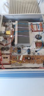
So I have this turntable & speaker system, it's very old and seems to be very un-documented online. Thankfully the internal circuit is extremely simple with a mains transformer, a metal 2 prong rectifier, an EL84 tube, a 2x32uf smoothing cap and an audio transformer. Additionally a couple resistors and small caps.
I've fully serviced the turntable, stripping down all the mechanics and cleaning them - it runs like a dream. I've replaced the metal rectifier with a 1n4007 diode + a 100ohm resistor. The smoothing cap is in-spec so I left it, as are the 2 resistors and small caps found elsewhere. The EL84 seems fine, but I've got another on hand too - have tested it with both with the same results.
Voltages are good, turntable is good, sound is good - what's the problem?
Well, the mains transformer makes a REALLY loud buzzing noise. I've never heard a transformer make this kind of noise before, it sounds like a ratchet constantly spinning. It's loud enough to make the deck basically unusable for listening to music. Having physically detached the transformer and moved it away from the rest of the deck while keeping it connected by wires, i can confirm that the noise is 100% definitely coming from it and not the rest of the circuit or the speaker.
Does anyone have any suggestions here? I cannot find any information about this transformer online, or schematics for the deck, but the transformer seems to be stepping mains voltage up to about 330v for the EL84. I presume I have no choice but to replace it, but I have no idea how to gather the information I'd need to do this correctly. It has 4 wires on its secondary, two going to the EL84, one going to the rectifier diode (which then goes to the smoothing cap) and one going to the metal chassis. If there's any other solution available please let me know.
I can say one thing - the noise isn't present when you first turn it on. It comes on as soon as the valve starts warmly glowing, after about 10-15 seconds.
I'm testing the device through a dim-bulb tester with a 70w bulb, which barely lights up at all. The buzz happens when plugged directly into the wall too.
R
DIY amp - symasym or something else?
- Solid State
- 10 Replies
Hello forum,
I'm thinking about building a symasym amp but I think I missed the right time by 10 or 15 years or so. It still has a good reputation for sound and it doesn't look so hard to build. I'm not an expert but I'm OK with the soldering and the enclosure building. For the AC part, first powering up and trouble shooting I have some help from a friend so I should be covered at this end.
Just wondering if there are other, similar diy "open source" amps out there. To fit the shoe it should have an active community, parts should be easy to come by and of course it must sound nice. Power is not too important, symasym classic has plenty of power for what I need.
So please let me know if there are alternatives worth researching or if you have built a symasym recently (withing the last 5 years or so) and you would do it again I'd be happy to hear about that, too.
Thanks for your time
6.5" + 1" low distortion design
- By zerokelvin99
- Multi-Way
- 7 Replies
Hi All,
I am looking to improve my living room setup (detailed below), and have a proposition I’d like to pass by you all to check I’m barking up the right tree!
Current setup
I currently own a pair of Void Mycro 6s (http://voidacoustics.com/uploads/Mycro-6-manual_1.pdf). They just about satisfy my SPL requirements, but are far from Hifi. I have modded them by filling ports and extra wadding - but still fall a little short.
Bass is handled by my dual 8” PPSL (http://www.diyaudio.com/forums/subwoofers/303976-sorely-tempted-ppsl-3.html), filling in below 120Hz. Power is a Lab Gruppen FP2400Q, providing 380w per Mycro 6 and 1280w to the 8” PPSL. DSP is handled via a DCX2496, with a Focusrite Saffire DAC.
Proposal
I would like to build pair of replacement speakers for the Mycro 6s that will, in approximately the same package, exceed their SQ - while maintaining SPL output. Budget approx £450.
I aim to do this by a new cabinet, that improves on several areas of the Mycros:
⁃ BMS 4524 compression driver, crossed at 2kHz.
⁃ Elliptical (?) horn, W90, H40 dispersion (?). 3D printed in ceramic.
⁃ B&C 6NDL38, crossed to sub at 120Hz
⁃ Sealed cabinet (4.5L), Q=0.707
⁃ Stiff cabinet (18mm MR MDF)
⁃ Zero parallel cabinet walls (heavily trapezoid, slanted top)
⁃ Flat front with tapered edges, minimising baffle step / effects
⁃ Active crossover. I have a spare TAS5630 I can use for tweeter (100w @ 0.1% THD @ 8R)
⁃ EQ through REW
Crossovers
BMS4524 was chosen due to its ideal 2kHz crossover, and extended response (20kHz+). Also heard great things about it on the interwebs.
HF response of the B&C is fantastic, but LF is a little on the edge. I propose to cross it at 120Hz to the sub, but by letting its natural roll-off do the work, with a 70Hz 2nd order to protect excursion @ 200w. This sims the same as a ported version of the same with a 120Hz 2nd order crossover. (The sub will have a 120Hz LP)
Summary / questions
⁃ My original plan was for a sealed 8” driver, but struggled to find a nice 1” that would cover the extended range to prevent beaming (1.3kHz+). Is there anyway around this or is there any need? 6.5” + 1” seems to be a nice sweet spot.
⁃ I have chosen Elliptical horn due to its constant directivity. My listening position shifts alot in the horizontal plane, hence the 90x40 dispersion. Is this still the best choice? I was toying with Tractrix, but is a little to directional maybe.
⁃ Would MTM make sense / be worth the extra space?
⁃ Is the natural roll-off a suitable method for crossing the LF of the 6.5”? Or will I run into phase weirdness?
⁃ Any other driver suggestions? I have looked primarily at BMS, B&C and Beyma offerings.
⁃ Will this sound a marked improvement better!? (Or do I need to go further…)
Thanks everyone who made it this far. I am looking forwards to your responses 😀
RIP Jacob Desvarieu
Jacob Desvarieu,
Composer and member of carraibean's band KASSAV' passed away at 65 ( covid).
The guy was a GREAT musician and had an incredible voice ( most women i know just melt when they hear his deep 'rocky' voice).
KASSAV' - LIVE MWEN DIW AWA - PARIS ARENA LA DEFENSE - YouTube
He was very friendly and human guy too as other members of the band ( was lucky to work in a room next to them for some weeks 20 years ago).
We lost some great artists this last week... 🙁
AV400v2 - Another 400W Hi-Fi audio amplifier with remarkable sound
- By donpetru
- Vendor's Bazaar
- 17 Replies
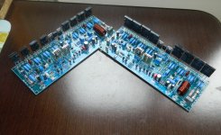
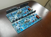
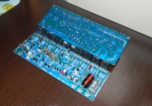
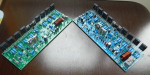
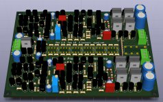
First, AV400v2 is much improved amplifier compared to the old AV400 amp. So, AV400v2 is a personal version of the amplifier AV400 or, in other words, how should it look old AV400. If I've sparked your curiosity even a little, then I invite you in this topic to buy even a piece of PCB AV400v2 which includes documentation of the amplifier assembly (including circuit diagram). Documentation amplifier is printed on paper (black and white).
AV400v2 is a (400W - 4 Ohm) compact audio amplifier, Hi-Fi, with good performance, which we subjected to various tests, as you'll see in the videos below. In the two videos below (excuse me, I haven't made a subtitle, but the images are quite suggestive), I tried to highlight what this amp is capable. Unfortunately, Xvid video quality is not the best, maybe even the sound (which is compressed to 192kb/s), but important things you can see see and hear.
AV400v2 is presented in two versions: AV400v2.1 and AV400v2.2 (using the same PCB). AV400v2.1 is MOSFET output transistor and AV400v2.2 is BJT output transistors.
1. TEST AV400v2 - BJT version:
https://www.youtube.com/watch?v=AzytSB64M6M
2. TEST AV400v2 - MOSFET version:
https://www.youtube.com/watch?v=hCpAUlpthC0
In recent years, I have performed various tests, especially with MOS-FET pair IRFP240 and IRFP9240 and, one thing revealed in many technical audio books, indeed, an audio amplifier with MOS-FETs sounds best if he sandwiched one driver pair transistors between VAS amp stage and output stage.
I even made a comparison in this respect. In fact, both AV400v2 amplifier, and GX400 have passed in recent years by some tests - including tests of various topologies (example: Output Triple amplifier...) - and after this I got the version presented.
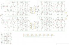
AV400v2 PROJECT or AV400v2 Documentation contains 10 pages with these "chapters":
1. AV400v2 - Cover
2. AV400v2 - Electrical diagram v2.1 and 2.2
3. AV400v2 - List of electronic components
4. AV400v2 - Indications for operation amplifier
5. AV400v2 - All Layers PCB
6. AV400 v2 - PCB Copper Top
7. AV400 v2 - PCB Copper Bottom
8. AV400 v2 - Drill Info
DOCUMENTATION (printed black and white) is valid in English.
PCBs prices are as follows (PCB size = 216 x 79 mm) :
1 pcs. PCB AV400v2 = 19 USD (includes printed above project to help in assembling the amplifier).
2 pcs. PCB AV400v2 = 36 USD (two pieces include with printed project mentioned above, to assemble the amplifier)
Who buys more than two pieces, the price is 17 USD/pcs. PCB.
I have available built units in two forms (without the heatsink):
a) fully assembled at the price of 85 USD / piece (see pictures below - in this moment only one piece available with MOS-FET).
b) semi-assembly built units - price of 82 USD / piece (I currently only available 4 pieces but depending on demand, I can assemble some extra).
WARNING! semi-assembly built units isn't soldered output transistors, drivers and bias transistor. So, these components will come separately along PCB. After that, depending on how the PCB clamping the heat sink, you have glue them.
Payment can be made via pay-pal at:
tehnium[dot]azi@gmail[dot]com
For more details please contact me via private messaging diyaudio.com or via email: donpetru@gmail[dot]com
AV400v2 amplifier needs 1.2Vrms on the input in order to deliver nominal power. Supply voltages are +/-(40 ... 80)Vdc.
AV400v2 is a (400W - 4 Ohm) compact audio amplifier, Hi-Fi, with good performance, which we subjected to various tests, as you'll see in the videos below. In the two videos below (excuse me, I haven't made a subtitle, but the images are quite suggestive), I tried to highlight what this amp is capable. Unfortunately, Xvid video quality is not the best, maybe even the sound (which is compressed to 192kb/s), but important things you can see see and hear.
AV400v2 is presented in two versions: AV400v2.1 and AV400v2.2 (using the same PCB). AV400v2.1 is MOSFET output transistor and AV400v2.2 is BJT output transistors.
1. TEST AV400v2 - BJT version:
https://www.youtube.com/watch?v=AzytSB64M6M
2. TEST AV400v2 - MOSFET version:
https://www.youtube.com/watch?v=hCpAUlpthC0
In recent years, I have performed various tests, especially with MOS-FET pair IRFP240 and IRFP9240 and, one thing revealed in many technical audio books, indeed, an audio amplifier with MOS-FETs sounds best if he sandwiched one driver pair transistors between VAS amp stage and output stage.
I even made a comparison in this respect. In fact, both AV400v2 amplifier, and GX400 have passed in recent years by some tests - including tests of various topologies (example: Output Triple amplifier...) - and after this I got the version presented.
AV400v2 PROJECT or AV400v2 Documentation contains 10 pages with these "chapters":
1. AV400v2 - Cover
2. AV400v2 - Electrical diagram v2.1 and 2.2
3. AV400v2 - List of electronic components
4. AV400v2 - Indications for operation amplifier
5. AV400v2 - All Layers PCB
6. AV400 v2 - PCB Copper Top
7. AV400 v2 - PCB Copper Bottom
8. AV400 v2 - Drill Info
DOCUMENTATION (printed black and white) is valid in English.
PCBs prices are as follows (PCB size = 216 x 79 mm) :
1 pcs. PCB AV400v2 = 19 USD (includes printed above project to help in assembling the amplifier).
2 pcs. PCB AV400v2 = 36 USD (two pieces include with printed project mentioned above, to assemble the amplifier)
Who buys more than two pieces, the price is 17 USD/pcs. PCB.
I have available built units in two forms (without the heatsink):
a) fully assembled at the price of 85 USD / piece (see pictures below - in this moment only one piece available with MOS-FET).
b) semi-assembly built units - price of 82 USD / piece (I currently only available 4 pieces but depending on demand, I can assemble some extra).
WARNING! semi-assembly built units isn't soldered output transistors, drivers and bias transistor. So, these components will come separately along PCB. After that, depending on how the PCB clamping the heat sink, you have glue them.
Payment can be made via pay-pal at:
tehnium[dot]azi@gmail[dot]com
For more details please contact me via private messaging diyaudio.com or via email: donpetru@gmail[dot]com
AV400v2 amplifier needs 1.2Vrms on the input in order to deliver nominal power. Supply voltages are +/-(40 ... 80)Vdc.
Attachments
-
 AV400v2 foto 1.jpg493.5 KB · Views: 1,543
 -
 AV400v2 foto 2.jpg514.9 KB · Views: 1,454
 -
 AV400v2 foto 3.jpg435.3 KB · Views: 1,383
 -
 AV400v2 foto 4.jpg440 KB · Views: 1,345
 -
 AV400v2 - foto 5.JPG826.9 KB · Views: 1,291
 -
 AV400v2 - foto 6.JPG836 KB · Views: 411
 -
 AV400v2 - foto 7.JPG816.2 KB · Views: 322
 -
 AV400v2 - foto 8.JPG821.9 KB · Views: 370
Discrete preamp / headamp based on cascaded diamond amp
- By suzyj
- Analog Line Level
- 23 Replies
This is another design stemming from my forays into low power, reasonably high performance amps with jellybean transistors (BC547, 2N3904/3906, BD179/180).
My "power amp" designs from this are in the single-digit PPM distortion range, so I wanted something to preserve that and give me an accurate volume control.
The first section is a three-stage amp with a diamond follower after the VAS, this then drives a six-bit relay based attenuator, then the output of that goes into a driver stage (another three-stage amp), with a cascaded diamond driver on the output.
On simulation for the composite amp I'm getting around 3nV/sqrtHz input referred noise, gain adjustable from -31dB to +32dB (in 63 1dB steps), and 1 PPM 10KHz THD pushing 10V into 50 ohms.
It's designed to be reasonably friendly, with DC servo to keep offset down, plus clipping management in the output stage. It'll drive loads down to ~8Ω with no problems, including headphones and little full-range speakers.
I've added a few parts to the input to allow flexibility in source - it can be set up so that either (or both) sides are inverting or non, so can be used as either a stereo single-ended preamp or a mono differential preamp.
I've added a regulator for the front end stage and DC servo, as the DC servo compromises PSRR a little (reducing it from ~90dB to ~60dB). The reg adds ~60dB PSRR.
The whole lot is on a simple 127mm x 100mm PCB. MELF resistors and diodes, 1206 caps, and a mere 157 through-hole transistors. With no exotic parts it should be fairly straightforward and reasonably inexpensive to build.
Attached LTspice sim of the amplifier chain, plus a couple of screen grabs of schematic and PCB, plus zip file containing all the design files in KiCAD format, including Gerbers for manufacture.
Attachments
Will a 2CH amplifier work with one channel cut out?
- Class D
- 9 Replies
Sorry newbie question. I am looking at purchasing amp innards.
In the link below, the power supply and channel modules are clearly evident.
https://sc04.alicdn.com/kf/H0e65a56...026994/H0e65a56cbe0e49cb893374ad487ff089y.jpg
This is a two channel class D amp, but I'm looking at putting together a one channel sub amp based on the innards of this one.
Am I able to simply use one channel module or is the power supply designed to only run with two channel boards connected?
Cheers
Ordering from Lii Audio..
- By MisterDK
- Full Range
- 4 Replies
Can anyone tell me how long it take receive Lii Audio drivers when ordered from USA and approximately what shipping will cost to California?
Thanks - Duane
Thanks - Duane
A single ended bright amplfier
- By doktor bob
- Solid State
- 2 Replies
This is a power amplifier i bild 5 years a go.
it measers as follows :
Uout 14V 20hz 0,30% 25W bij 8ohm
Uout 14V 1kc 0,90% 25W bij 8ohm
Uout 14V 10kc 1% 25W bij 8ohm
Uout 2,8V 20hz 0,08% 1W bij 8ohm
Uout 2,8V 1kc 0,02% 1W bij 8ohm
Uout 2,8V 10kc 0,03% 1W bij 8ohm
R.out 20Hz tot 20kc 0,45ohm df =18 bij 8ohm
10V 8ohm 10hz -0,4db tot 200kc -3db
28db (0,6V =14volt out)
it is stil in use by a freind of mine in combination with Ariel (lynn olson)
Attachments


What Neurochrome amp should I get?
I'm interested in trying a Neurochrome amp to pair with 101db horns (Wayne Parham's 7pi) Can anyone help me with sonic differences between 186, 286 and 686 amps? I'm looking smooth, transparent, effortless sound and I want to get the most out of the build in terms of sound quality without overspending on unused power. Thanks so much for the help!
Class D Inductors
- By Coil2021
- Vendor's Bazaar
- 2 Replies
How to store the inductor after purchase? Here have three methods help you management the extra inductor .
1. The storage conditions of the product in the package: temperature 5~40℃, relative humidity less than or equal to 70%, if taken out and used, please seal the remaining product with a plastic bag and store it in accordance with the above conditions to avoid oxidation of the terminal (electrode) and affect the welding state .
2. The storage period of Kedajia electronic products is not recommended to exceed 12 months. Under other influences, the terminals may be degraded, resulting in poor solderability. Therefore, all products should be used within 12 months based on the shipping date.
3. Please do not store CODACA product in an unsuitable environment with high temperature, high humidity, dust and corrosive gas. .
Attachments


DS18 H-K08
- Car Audio
- 37 Replies
Amp came in with blown power supply fets .
I replaced the fets and 2 driver ic’s didn’t replace the smd transistors yet .
When trying to power the amp up it shows no signs of life .
Any ideas ?
I replaced the fets and 2 driver ic’s didn’t replace the smd transistors yet .
When trying to power the amp up it shows no signs of life .
Any ideas ?
new Renardson amp
- By dimitri
- Solid State
- 16 Replies
May I draw attention of the respected diyers to a new amp by Mr. Renardson
http://www.angelfire.com/ab3/mjramp/newamp2.html
The PCB will be available soon, if you need it, drop a note to Mr. Renardson
http://www.angelfire.com/ab3/mjramp/newamp2.html
The PCB will be available soon, if you need it, drop a note to Mr. Renardson
Attachments
Technics SL1200 / 1210 Speed Fluctuation Problem
- Analogue Source
- 16 Replies
Hi
I've found this site whilst trying to research a problem I have with my technics SL1210 Mk2. I've searched the forum but can't find anyone describing the subtle speed changes I am experiencing.
I have two of these decks, for DJ'ing, but recently one of the decks has developed a fault where the speed constantly oscillates around what I presume is the speed it should be turning at.
This isn't audibly noticable, but it causes huge problems when trying to beat match records as one record drifts all over the place and continual correction of this 'drift' means the mix will never actually sound cohesive.
The fluctuation is in the order of tenths of a percent, and occurs at all positions of the pitch fader, including at the zero position. I have come to this conclusion by playing two copies of the same record and hearing it drift from being in time, to too fast, to back in time, to too slow, etc., etc., so I'm pretty certain this is what is happening.
I've put a new pitch fader in the deck anyway as it is 15 years old and never needed servicing, but I guess something else is wrong and causing this problem... I am very willing and able with a soldering iron, but I don't have anything other than basic test equipment, i.e. a multimeter. I'm up for replacing as much stuff as it takes to fix this problem and have a bit of a stock of capacitors, etc.
If anyone can offer any advice it would be seriously appreciated as I don't have the time to send the deck off for repair anywhere.
Thanks.
TPA3118 test: something's wrong
- Class D
- 9 Replies
Hi, I just bought a few Texas Instruments TPA3118 boards to test out for a mono boom box. I bought the very plain type with only the chip and in/mute/power/out solder points.
The other components in my test bench are a Dayton Audio PS65LP-4 (4 Ohm, 99 dB sensitivity), a multi-purpose laptop charger set at 19V output, and a 100K log pot on the signal. The input jack has the two channel positives shorted to mono. All components are brand new.
After putting everything together I noticed a few obvious issues with the sound that I had not heard about in any of the forums dealing with this chip:
1. The sound is extremely low, with no bass. With the pot at max level I get a sound that's similar to a budget laptop speaker, even worse in terms of bass (I am regulating the volume from my cell phone). With a 99dB speaker and a 60W amp, I should have blown up my neighbor's ears by now...
2. The pot seems to do very little difference. Even at minimum I have a signal, and it's clearly lower than at max, but not what I expected from a 100K pot. I even soldered an additional 100K resistor in series, which made little difference.
3. Even changing the input voltage from 19 to 15V and back makes very little difference.
OK, the speaker has no enclosure and the system has not been broken in, but this is way worse than any other brand new system I have put together before.
See attached photo of the assembled system. I double checked input and speaker polarity, and input signals. Can anybody think of any obvious flaw (except for a defective board)?
Thanks.
gm
Attachments

Spendor S100 Speakers
Hallo all.
I need some advise plse. I have a pair of Spendor S100. I have read about rubber surrounds getting hard and stiff. I have checked and saw that the surrounds on the midrange and 12inch woofer are indeed extremely stiff. So you will need an extreme amount of watts to move the speakers. I suppose there is no way to soften the rubber surrounds. I have read about brake fluid but are to scared to try it. Do you guy's have any advice plse. If I can get replacement surrounds, do anybody perhaps now where. The bass woofer has weird surrounds, not like normal ones.
Help appreciated !
Regards
What can you build with 2n5457 and 2N5460 JFET's
- By DualTriode
- Solid State
- 9 Replies
Hello All,
What can you build with 2n5457 and 2N5460 JFET's?
Years ago I back ordered 2500 each of 2N5457 and 2N5460 JFETS. Mouser shipped these just a couple of days ago , they will arrive soon.
Thanks DT
What can you build with 2n5457 and 2N5460 JFET's?
Years ago I back ordered 2500 each of 2N5457 and 2N5460 JFETS. Mouser shipped these just a couple of days ago , they will arrive soon.
Thanks DT
An old W-Bin....
- By Brian Steele
- Subwoofers
- 68 Replies
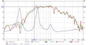
I'm helping my brother repurpose some speakers for a new place that he's putting together. Amongst them are two old W-Bins containing B&C 18TBX1000 drivers. I took the opportunity to do some measurements of one of them (see attached). They are vented, and I used the transfer function method to measure the contribution of the vent to the output.
Apart from a narrow dip around 119 Hz, these W-Bins seem to have a pretty decent and smooth output. -3dB point is at 45 Hz, and the vents tune the chamber to around 33 Hz, which is pretty low, but it seems to do the job, with the vents adding around 2dB of additional output between Fb and 60 Hz. The vents are two 3.5" cylindrical tubs though, which might be on the small side for a 18" driver.
I told my brother that I might design a different box for him based around the same drivers, but I think it might be a bit difficult to get something noticeably better than these W-Bins, considering the type of music that they usually play.
10-JUL-2021: Added corrected response curve, as previous measurement included the impact of my car stereo's "ASL". See post #20
Attachments
Separating multiple trigger burst into individual triggers
- By AshtrayWasp
- Construction Tips
- 14 Replies
I need to separate a burst of three triggers into only one pulse so I can only use the first one to trigger another circuit, as I don't want it to re-trigger with every pulse, is there a simple circuit that can do this? It's coming from a sequencer cpu so I can't really reprogram anything.
Early Quad 303 refurbishing
- By Crystalboy
- Solid State
- 13 Replies
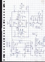
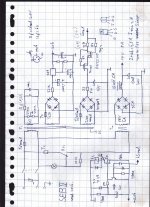
First post here! Have been lurking around here for over three years, but never registered. Last weekend I bought a really nice early Quad 303 along with an early Quad 33 unit. Both have serial numbers #11xx. I have been recapping both during the last couple of days. I tuned the rail voltage as well as quiescent current last night and fired the 303 up. Left channel is working flawlessly but the right one is noisy with volume set to zero. I thought the first order of business was to order replacement resistors for the larger carbon composite ones, which usually go bad. I thought of 0.5w metal film resistors. Would that be appropriate? As I've understood it this version has the first boards, and it's hard to find any info on these on the web. Thankfully it included schematic for the 303, which seems impossible to find online. I'm gonna make a scan of it later on if somebody might need it as well. My second question is, C104 is a bipolar electrolytic (I assume?) capacitor on this version on the driver boards. Is it okay to change it with a polarized capacitor instead as in the later versions of the boards? See pictures. Thankful for any input!
TSE-II Inverted Assembly
- Tubelab
- 3 Replies
I have just started soldering parts on a TSE-II board.
Can I do inverted assembly, i.e. just the sockets on the top side of the board (the one where TUBELAB TSE-II is printed), and place all the rest of the parts on the other side?
How about Mosfet and other semiconductors? Will I run into issues with polarity and heath-sink position?
Thanks
Can I do inverted assembly, i.e. just the sockets on the top side of the board (the one where TUBELAB TSE-II is printed), and place all the rest of the parts on the other side?
How about Mosfet and other semiconductors? Will I run into issues with polarity and heath-sink position?
Thanks
4 Channel SSE?
First a little bit of context, I've already built the SSE and since doing that my main speakers I liked listening to on tube power were sold (la scalas) and were replaced with jubescalas, since they require active crossover I now need four channels of amplification.
Few questions:
-Would the Edcor XPWR222 be up to the task of running a pair of SSE boards? For reference it's rated at 350mA 375-0-375, 6A 6.3V and 6A 5V. I feel like the 6.3V filament winding won't be able to handle two boards but I want to be told that instinct is correct.
-Assuming the Edcor I have won't be up to the challenge, is there anything out there that would be? The One Electron BFT-1B looks promising but will the secondary at 385-0-385 be too high? (For reference my mains voltage runs a pretty consistent 119V)
-Will there be any fundamental issues introduced by running a pair of SSE boards from one PT? Should I be considering dual PTs?
-If I'm running these purely as power amplifiers with no need for volume control do I just omit that and run the inputs directly into the board?
-My outputs are balanced, has anyone done a balanced input mod on the SSE? Is there any value to that besides the "Shlick-snap" satisfaction of XLR connections at both ends?
-I currently have 15W GXSE edcor OPTs I will be re-using for the high frequency portion of this 4 channel thing. They'll be powering a pair of B&C de75p compression drivers that are 8 ohm nominal and 108db sensitivity. For the low frequency pair of channels should I go with the larger Edcors? The frequency response isn't that important as the horn bins can barely touch 50Hz but they are around 3dB less sensitive so will be getting more power day to day.
A few notes, I'll be tube rectifying and my output tubes right now are a pair of Shuguang Black Treasure KT88's so I'll probably grab another pair of those.
Thanks for any tips or guidance, and yes most of the desire to make this in one unit is the visual spectacle of 8 warm tubes and a small city of transformers, chokes and caps.
Getting max output from a TK2050 T1 amp on battery power
- By sylvanshine
- Class D
- 0 Replies
Hi all,
New here, though I've learned a lot from lurking threads for a while. I'm basically a noob when it comes to this stuff despite being a reasonably experienced sound engineer.
I've rigged a hifimediy T1 tk2050 amp up to an old passive PA cabinet (an EV SH1512ER, rated to 200W at 8ohms) to run off 24v battery power. I have a small powered Rolls powered mixer as a preamp adding about 26db of gain running into a small passive crossover and mono sum i built (off of this design MonoXover 2-way Pre-amp Audio Crossover : 4 Steps - Instructables), which runs directly into the the amp's inputs (so its bi-amped as one channel to the tweet one channel to the 15" woofer).
It all works and i'm stoked on it, it sounds quite amazing in fact. However, I'm quite sure that I'm not getting what I think should be max output of the system and am trying to figure out where my weak point is. I have a few clues and wonder if anyone here has thoughts or suggestions:
1) First, obviously the amp is underpowered for the speakers. I might consider replacing the T1 (2x100W) with a T4 (2x180W) which i know might give me close to double the clean volume I currently have. Still i think i can get more with the T1.
2) The T1's input voltage is rated up to 39v. If i add another 12v battery in series to what i have to bring it up to 36v, I'm sure i'll get more power - would this increase my output significantly or only marginally? Anyone with experience here?
3) I'm running the Rolls preamp at 12v instead of 15. I'm probably losing some headroom here. Unfortunately they seem to have changed the input voltage of the MX51s to 15v without updating the specs online, i thought it was 12v max when i got it. Still dont imagine this is the main problem (although I do hear it cracking up at the very top 10% of its range).
4) Lastly I wonder about input impedance on the amp itself. I've seen people reference changing 2 resistor values on the PCB of the amp itself to decrease impedance on the input section of the amp and get more volume flowing. Any experience with this?
Thanks in advance for any thoughts or ideas. Best wishes to all
Jeff Bagby Kairos with PP Tube Amplifier
Hello.
Has anyone tried Jeff's Kairos with a pp tube amp? Is this a good combination? Or does the Kairos need a transistor amplifier?
Sorry for my poor english.
Has anyone tried Jeff's Kairos with a pp tube amp? Is this a good combination? Or does the Kairos need a transistor amplifier?
Sorry for my poor english.
TDA2050 Bridge Amp
Hello everyone. I want to build an amp to drive a 20" 4ohm 150w max subwoofer in a car. I'm planing to use boostor project to boost supply voltage from 12v to +-22v. I'm looking for an ic amp to deliver 70w-100w from said supply.
I've found the schematic below using TDA2050's in a bridge configuration claiming to output over 70w which is enough for me but TDA2050 is obsolete and i'm concerned fakes won't be able to handle +-22v supply voltage. Even if its a TDA2040 rebranded as 2050 it should fry according to datasheets.

What experience do you have on fake 2050 chips? Is it worth the shot? I'm open to new ic suggestions. Or maybe should i go with transistor amps? Any idea or recommendation is welcome. Thanks for reading.
I've found the schematic below using TDA2050's in a bridge configuration claiming to output over 70w which is enough for me but TDA2050 is obsolete and i'm concerned fakes won't be able to handle +-22v supply voltage. Even if its a TDA2040 rebranded as 2050 it should fry according to datasheets.
What experience do you have on fake 2050 chips? Is it worth the shot? I'm open to new ic suggestions. Or maybe should i go with transistor amps? Any idea or recommendation is welcome. Thanks for reading.
WTD: Ian Canada 9038Q2MPi Dual Mono Plus DAC HAT (UK based)
I have the v1 of this board and fancy trying out the plus version. Just wondering if any diyers in the UK have any surplus boards before I order a new one.
Behringer UltraCurve Pro 2496
- By g4xcp
- Digital Source
- 0 Replies
Behringer UltraCurve Pro 2496
D[book=]%[/book]oes anyone have the hex and bin file for the Behringer Ultra Curve 2496
version 1.4 or 1.7 so that i can write to the chip using the TL866II programmer, i have version two point five bin and hex which is not compatible with my older ultra curve
I am willing to share my version two point five rom
thanks please help
How do you know if your preamp has inverted the phase?
- Tubes / Valves
- 48 Replies
Its monday and I feel like asking a dumb question.
I read somewhere that out of phase stages in a preamp can cause some loss of listening pleasure.
So the dumb question is I have 2 stages in my preamp for phono (Ixys current reg on each anode with output of 1st stage off anode into grid on stage 2 (which also has an Ixys reg on it) feeding into an srpp line stage?
So what is the rule of thumb here?
Thanks
Nick
A little study about two old germanium projects
- By DIYBras
- Solid State
- 22 Replies
Hello friends of DIYAudio,
In last times I am making a lot of measurements, and someimes I like to dissect some projects, like this I show here: one Germanium amplifier, and a Germanium preamplifier. Both more or less "classics". The amplifier in one using AD161/AD162 output transistors, and the preamp is like one published in Discrete design: 2-transistor RIAA preamp (the Linsdale MM, with some minor alterations).
In next posts I will show the results (and I need to draw the schematics 😱😱 ) normally I build things WITHOUT schematics 😛😀
250Hz-2kHz horn for B&C 8PE21
Hi,
I,d like to build a horn for 8PE21 to be put between B&C DE250 attached to FaitalPro LTH102 horn and 15'' woofer in OB (FaitalPro 15FH510).
I hoped I would be able to find tons of projects or plans for such a "horn friendly" driver but I couldn't find anything for the given application. Hence the thread.
The idea is to cover 250-2000Hz band without any (or very little) EQ. Something Avantgarde midrange horns like. I thought I would modify the project from speakerplans.com website:
Speakerplans.com
Instead of two 10'' drivers I'll use one 8PE21 and downsize the horn proportionately: instead 15x21cm thorat (for one 10'' driver) I'll have 12x16,8cm (proportionate reagarding Sd of the drivers). And by the same method the mouth width would be 48cm instead of 60.
The big question is:
Is it totally insane? 😀
I'd appreciate any valueble comments, ideas etc. I tried to use Hornresp but propably too stupid for that. I didn't buy the 8PE21 yet so they are not a must. What matters is the frequency scope and, if possible, Xover-less design.
Thanks.
Chris
Faital 8PR200 + HF10AK + Seos10 + Fusion FA122
Hey guys, this is my first post on here and my first venture into an active 2-way speaker. I currently own DIY Sound Group HT-12s as part of my cinema set-up and love the way they sound and want to build a second pair of similar style speakers for a desk-top monitoring/ mixing set up at high spls but whilst also having crystal clarity.
I would like the 2-way to consist of an 8" mid-bass driver and seos 10 waveguide so as to keep the size of the cabinet to a minimum, the HT12's are huge in comparison. I am seriously considering the Faital Pro 8PR200 and the Faital Pro HF10AK for this combo as I have heard great things about both drivers, although I am reading a lot about the B&C DE250 which is on sale right now and £40 less than the Faital. This will be an active speaker using one of the Hypex Fusion Plate amps. I have yet to learn the software but should be able to get to grips with it pretty quickly.
I would love the speaker to be able to play down to around 40hz, however I realise I may be asking to much from an 8" and may need to pair these with a sub. Originally I was planning on porting the speaker, using an internal volume of around 20l and ported to 45 (ish)hz, however I can't seem to model a port that works. The velocity is either way to high or the port resonance is way too low. I assume I would cross somewhere in the 1.5khz range, but I can't seem to get the 1st port resonance above this with a useable velocity. How important is it that the resonance is kept out of the passband for the mid-bass driver and is there any way of telling if it would be a problem in the passband? I suppose this would show in any measurements I make pre-crossover.
I have a UMIK1 and was hoping this would be adequate for taking any measurements I need to make.
As I say this is my first from-scratch build. Any advice on the components listed would be great.
Can use car active crossover in home ,is sound like home active crossover ?
- By Pigy
- Analogue Source
- 3 Replies
Car active crossover is cheaper from home version,but I don't now sound quality for these. Difference in sound?
Computer DSP PLUS External Analog Frequency Splitter??
Hey guys
Ok, I want my system do use a DSD dac but I also want to biamp my speakers plus have 2 subs. There aren't many (hardly any) DSD DACs with >2 channels.
So, what about doing DSP correction at a 2-channel level and then go from the DAC to an active analog crossover (like a Marchand) to get me 6 channels of output.
Does that make sense? Or would the phase get screwy?
By the way, DSP correction would be for the room and would be via convolution (Audiolense).
Thanks!!
Jim
Full Range 2 Way with hifi woofer and horn/CD
Designing this for a friend who wants a full range classic style enclosure (similar size to Klipsch Heresy) with a compression horn mid/tweeter.
He already has a Radian 745NEO comp driver and I am thinking to use 18 Sound XT1464 for a crossover point of around 800hz to an SB acoustics SB34NRX75 or SB34NRXL75-8. There are other 1.4" horns like the Ciare and Faital also that I would consider.
SB Acoustics SB34NRX75-6 12" Woofer
SB Acoustics SB34NRXL75-8 12" Woofer
https://www.eighteensound.it/media/...TBfNTZfMzZfMTY4X1hUMTQ2NC5QREYiXV0/XT1464.PDF
745NEO - 3″ Diaphragm, 1.4″ Exit - Radian Audio
Speaker will be actively bi-amped so sensitivity mismatch is not so important.
Bass requirement is around 30hz flat in room or better at moderate/high SPL for music. Enclosure will be 80-100L and 500 wide by 750 tall.
Has anyone tried this slightly unconventional mix of hifi woofer with comp driver and horn and what was your experience? Do you think the SB woofer will be clean enough to 800-1000hz for crossover?
Thanks
Attachments

2.5inch Full Range T-line Speaker
- By wchoi41
- Full Range
- 5 Replies
Hello, friends!
I'm new to this forum, so please understand me if I'm making a mistake by asking this question here.
So... here's the question.
I'm building a t-line full-range speaker that will be embedded into a musical instrument. I've designed the enclosure in Hornresp, and it looks pretty good... but I'm a huge noob.
I'm afraid I've made a mistake somewhere, or if I'm missing out on an opportunity to make it better. So here I am, begging for your help : )
This is the link to the driver I'm using: https://www.tectonicaudiolabs.com/wp-content/uploads/2019/01/TEL-DS-TEBM36S12-4A_Revision1.6.pdf
This is the Hornresp simulation I'd done.
1 — ImgBB
2 — ImgBB
3 — ImgBB
Do they look okay?
Also, the vent of my t-line will not be facing the same direction as the speaker. It'll be on the side of the enclosure. Would that cause any trouble? : (
Would really appreciate any help from you guys!
Quad 303 Upgrade - How far is too far?
- By HiFiWill
- Solid State
- 19 Replies
Hi, I've owned a 303 for a year or so now, it had the original capacitors so I refurbed it with the Net Audio capacitor kit and replaced the butchered front plate with a home made one which included proper input and output sockets and some decent mains in and out sockets. So it's "sort of" original (at least sound wise). I use it with my 57s. and I like the results. (Incidentaly I use a DAC to feed it, am I the only one? Most people seem to spend time and money upgrading their Quad pre amps and still people knock them).
I just bought (maybe unwisely) another 303 and I'm tempted to go the whole hog and get the two mono Net audio full upgrade kits. Has anyone gone down this road and is brave enough to give a truthful (not coloured by expenditure!) report of the outcome? Will I loose the Quad sound as some people say (do they actually know this to be so or is it just a desire to keep originality?). I suppose that if I do the upgrade and don't like it I can always put my first amp back as it is now and sell the second one with all the upgrades.
So, should I stick with what I have, or am I missing out on the 'wonders' of Mk3 upgrades and the 'essential' benefits of monoblocking to get the best from my 57s?
Some objective help, maybe on the outcome of each part of the upgrade process, required here!
Cent percent feedback query
- By indr
- Solid State
- 3 Replies
Is 100% feedback quite desired criteria for good amplifier design?
3e audio TPA3255 inductors running HOT
- By zerokelvin99
- Class D
- 5 Replies
All,
I own a 3E audio TPA3255 (TPA3255-2CH-260W | 3e Audio) which I sometimes run 53-54V (yes, I know that's high!)
I have noticed that the inductors get too hot to touch (80C+ I guess) when operating in this state.
Is this something to worry about? I have some active cooling to keep heatsink running nice and cool, but not sure if I should worry about forced flow over the inductors now? Would their performance be reduced in this hot state?
Kind regards,
Comb Filtering and how much it's audible ?
Title pretty self-explanatory 
... spin-off question: given a far-enough listening distance, is the comb-filtering effect will stay audible ?
... spin-off question: given a far-enough listening distance, is the comb-filtering effect will stay audible ?
Best low cost logic analyzer
- By Algar_emi
- Equipment & Tools
- 4 Replies
Hi. Looking to buy a usb small, economic, and pc based logic analyzer, 8 channels min. I used to have a small parallel interface logic analyzer, but it is time to update to a USB interfaced one. I found a lot of different offering on ebay/aliexpress for cheap, unexpensive ones.
I’m open to suggestion and would like to hear from other members that have more knowledge than me of the current market offering.
Seems there is a lot more unexpensive options these days than 20 years ago.
For example, just a few examples:
LA2016: New LA2016 USB Logic Analyzer 200M MAX Sample Rate 16Channels 2M PWM | eBay
Hantek, more serious 32ch module, but also more expensive: 32CH 150MHz 400MSa/s Digital Multimeter Logic Bus Analyzer Probe HANTEK 2G DDR2 | eBay
Cheap, usb powered module: New USB Logic 100MHz 16Ch saleae16 Logic16 Logic Analyzer for ARM FPGA | eBay
This is for DIY work, nothing fancy, but I still don’t want to damage my work laptop…
Thanks, any suggestion welcome
SB
-
Locked
New low-noise JFET from TI - JFE150
- By len_scanlan
- Parts
- 1 Replies
Just found a new part by TI - a low noise N-type JFET intended for audio. Datasheet says it's from Burr-Brown.
JFE150 data sheet, product information and support | TI.com
Looks kinda like it could be a BF862 replacement. Only tiny SC-70 package for now, but they mention SOT-23 will be available.
Thoughts?
JFE150 data sheet, product information and support | TI.com
Looks kinda like it could be a BF862 replacement. Only tiny SC-70 package for now, but they mention SOT-23 will be available.
Thoughts?
Aliexpress DIY tube amp in wooden chassis - static in one channel
- By casewindow
- Tubes / Valves
- 5 Replies
I built a 6J1/LM1875 amp kit from Aliexpress. I built it into my own wooden chassis with a metal backplate from an old amp.
In the left channel for some songs, quiet ones, for example the start of "The A Team" by Ed Sheeran, there is a static sound along with some of the song, but most songs, and later in this song, that disappears.
The issue goes away if I unplug the other RCA lead (the one for the right channel). The right channel seems to have the problem as well but immeasurably less.
Things checked
1. That the PCB ground goes to the metal backplate
2. That this is the only common ground
3. That the RCA shields are isolated from the backplate
4. That the binding post speaker terminals are isolated from the backplate
5. That the LM1875 chips are isolated from the heatsink (that is part of the backplate).
I have created my own DPDT switch system to switch between two inputs. So from a 2-input RCA (four ports) set of inputs the shields are connected between both sets of inputs. The left and right channels are kept separate and all of this goes to the DPDT switch which allows switching between channels.
The problem seems to be better, but not gone, if I subsitute just a two port RCA jack that connects directly to the input (bypassing the switch system).
I have tried connecting a 10nf ceramic capacitor from the RCA shield to the backplate (which is shared by ground) but this just created a ground loop
It's weird that the problem goes away when one RCA cable is removed.
WTB Lii Audio M6
I always liked the look of these Bakelite coned drivers and I quite fancy a pair. Depending on their worth if I can afford them I'd be interested in any offers.
Thanks
Thanks
What are these modified brown scanspeak revelators?
- Multi-Way
- 1 Replies
Stumbled upon this YouTube video which apparently shows a pair of modified scanspeak revelator 15W/8531K-00.
I have never seen those in Brown before. Any idea what has been modified and where they are from?
Modified Scan Speak 15W/8531K-00 5.5" Revelator - YouTube
I have never seen those in Brown before. Any idea what has been modified and where they are from?
Modified Scan Speak 15W/8531K-00 5.5" Revelator - YouTube
Need enclosure sugestion for Mark Audio CHR 120
- By Edu cbm
- Full Range
- 6 Replies
Hello,
I never heard a good full range speaker.
I´m from Brazil and here we dont have quality speakers for "home use" because the audio market here only have products for automotive (focused on SPL) or outdoor professional big events
I am thinking in buy from Madisound a pair of Mark Audio CHR 120 because i read that its have a very good bass extension, and it is what i am looking for
and i am in doubt whats enclosure would be the best for my use:
i have a small room 15m2
i hear mainly "old jazz" (miles davis, bill evans, jim hall, dave brubeck etc) and Rock (Beatles, Pink Floyd, Rush etc)
and i want an enclosure that could give the more clear and profound bass i could get from this songs
so from all the enclosure sugestions founded in the Mark Audio site ( CHR-120 | Markaudio )
what will be the one that probably will fit better in my room and in my expectations?
do you think i will be good have a subwoofer to help too?
PS: if there is another speaker in Mark audio (or other manufacturer) instead of CHR 120 that is better for what i want please let me know too
-
Locked
DIY Sony VFET lottery entry
This is it 🙂
This thread will remain locked until the first lottery entry window opens.
----------------------------------------
How to enter:
We're taking a "Hope for the best, plan for the worst" approach. We'll be monitoring the server and if it has any issues, the event will be extended until there's a full 15 minutes without issues. Additionally, if our database connection limit is hit (which prevents the server from overloading), you'll be provided an off-site link to enter.
----------------------------------------
Further reading and discussion:
This thread will remain locked until the first lottery entry window opens.
----------------------------------------
How to enter:
- Read the VFET Store Information Page
- Please go to diyaudio.com/vfet before the window opens
- You will be automatically redirected to the right thread 1-6 minutes after the lottery opens, to help spread server load. Please wait to be redirected. Thank you for your compassion!
- Post one short and sweet message ("In!" is fine...). Please wait until the window closes before making another post in the forum.
We're taking a "Hope for the best, plan for the worst" approach. We'll be monitoring the server and if it has any issues, the event will be extended until there's a full 15 minutes without issues. Additionally, if our database connection limit is hit (which prevents the server from overloading), you'll be provided an off-site link to enter.
----------------------------------------
Further reading and discussion:
Anyone familiar with this preamp?
- By Victorinox
- Solid State
- 13 Replies
Found this one at my local thrift shop. Anyone familiar?
OUTPUT TUBES ON HK TA5000X
- By wgh64
- Tubes / Valves
- 2 Replies
Right now my receiver is working pretty good but seems a little under-powered and is not incredible balanced channel to channel. I have a mismatched bunch of old untested 7355 power tubes (different brands), which I have balanced as well as the existing circuits allow. Plate dissipation is about 21 watts on Channel A and 19.5 on Channel B, both exceed the 7355 spec'd 18 watts rating. The existing circuits don't allow to lower/raise the bias of the push tube without rising/lowering the bias of the pull tube so all you can do is balance them. Because 7355 are too hard to find, I am going to change the tubes to 5881s, which are pinned out a little different but have very similar specs and 23 watt plate dissipation rating.
My question is this, the 5881 are slightly bigger around and while they fit in place, the clearance between the bottles and the output transformers is only about an 1/8" to 3/16"; the clearance with the 7355s is about 1/4" to 5/16". Is there going to be a heat problem with the output transformer that close to the power tubes ? Should I move them over to get a little more clearance?
My question is this, the 5881 are slightly bigger around and while they fit in place, the clearance between the bottles and the output transformers is only about an 1/8" to 3/16"; the clearance with the 7355s is about 1/4" to 5/16". Is there going to be a heat problem with the output transformer that close to the power tubes ? Should I move them over to get a little more clearance?
Folded horn coax?
- By PiMaxC
- PA Systems
- 3 Replies
Good morning.
I recently found a steal on my local Facebook Marketplace and snagged 4 Eminence Kappa Pro 15 LF2 drivers for less than the cost of a single driver. My grand plans are to turn one into a downward firing sub for my dining room, one is going into a bass guitar cabinet, and for the other two I wanted to do either a 2 or 3 way PA cabinet for my back yard.
Now my rather ambitious design idea was to build a set of folded W horn cabs with a small bass reflex box in the center that holds either a full range driver/horn, or a pro coax driver combo.
So my big question is does anyone know of existing folded W horn cab designs for this driver that I can make some mods to or are able to point me to the right things I need to tune the cab correctly?
some amplifiers for sale: Adcom, ATI, Behringer
- By CharlieLaub
- Swap Meet
- 6 Replies
Here are some amps I would like to sell from my stash. I will post pics upon request. Payment via PayPal.
All prices do not include shipping. Local pickup welcome near Lansing Michigan.
Adcom GFA-2535: SOLD !
ATI AT1502:
This is one of ATI's first power amps I believe. Very well built and has very solid bass. Rated for 150W into 8R, and you can bridge it for 450W into 8R plus 2dB headroom. I used this to drive some dipole subs for a time, but no longer need it. Cosmetically this is in OK shape, with a few scratches but nothing serious. The LED on the power rocker switch is a bit dim. Otherwise great working condition. I have a pdf copy of the owners manual. Weight is about 40 lbs. I do not have any original packaging but will pack well.
Asking $300
Behringer NX3000 with quiet fan mod:
I have two of these on offer. I replaced the stock fan with a high static pressure, low noise Noctua fan so that they are better for use with home audio. There are dyno tests for these amps online and they have lots of power (although NOT even close to 3kW!). These were originally obtained by me as factory refurbished models, so they were checked over and made as new before I replaced the fan. I never actually used them - I had a project for them that didn't pan out - so I am looking to find them a new home. Both are in good to very good cosmetic shape. I have the original box for one amp, and will pack the other well. They only weigh about 8 lbs!
Asking $250 each.
AR3a "improved" - It works!
If anyone has interest - The AR3a "improved" crossover works.
Please find the schematic and pictures of the finished result at :
www.diagrammer.hobbysider.dk and the AR3a "button".
The AR3a "improved" is ready for playing and sounds great - best with only the specified 1 Ohm serial resistor for the midrange and no reduction of the tweeter signal. Very open sound together with expanded stereo perspective and the well known AR woofer attack.
rgds
Attachments

JBL 075s Cone midrange horn, unity horn,???
So I have these two JBL 075 Ring Radiator bullet tweeters. At around 106dB/W/m It would take a lot of padding down to mate with normal speakers. So what to do. one could
1. By some really expensive compression driver based mid horns
2. Get a pair of 8 or 10 inch PA midranges per side (or a big line array of 4")
3. Some sort of front loaded horn based on full ranges I have laying around
4. Dive into unity horns using 4" or 6x9" drivers I have on hand.
So 3 and 4 are the most appealing. Can the 075s work firing into the end of a unity horn instead of a compression driver? Anyone ever use 6x9 in either front loaded MR horn or unity horn?
I would be expecting the midranges to cover about 500-5k.
Merging Passive radiator and Woofer nearfield question.
When merging nearfield woofer and nearfield passive radiator, are you looking to match up the bottom ends of the tails like you would with a port merge?
The reason I ask, is I am taking both measurements 1/4" from the cone, but I am having to adjust the PR response up almost 4dB in order to get the tails to match.
First pic, nearfield of woofer and PR, a copy of the PR raised to match the tail of the woofer.

Second pic, summation with matching tails.

Third pic, summation with no level matching.

I know I need to add mass to the PR, but before I start those trials, I would like to make sure I am summing them correctly.
This is to be merged with the farfield of the woofer for use in a two way crossover.
The reason I ask, is I am taking both measurements 1/4" from the cone, but I am having to adjust the PR response up almost 4dB in order to get the tails to match.
First pic, nearfield of woofer and PR, a copy of the PR raised to match the tail of the woofer.
Second pic, summation with matching tails.
Third pic, summation with no level matching.
I know I need to add mass to the PR, but before I start those trials, I would like to make sure I am summing them correctly.
This is to be merged with the farfield of the woofer for use in a two way crossover.
KEF 104B crossover schematic needed !
- By promitheus
- Multi-Way
- 35 Replies
Hello everybody,
I want to find some construction information on the KEF 104B speaker.
This speaker was a 2 way design that used a T33, a B200 and a 139B passive radiator. I need the box dimensions and the crossover for this speaker.
Thanks a lot in advance.
Greetings Ilias
I want to find some construction information on the KEF 104B speaker.
This speaker was a 2 way design that used a T33, a B200 and a 139B passive radiator. I need the box dimensions and the crossover for this speaker.
Thanks a lot in advance.
Greetings Ilias
Heatsinking pass transistors in series regulators
- By deafen
- Power Supplies
- 6 Replies
Did some searching and didn't come across anything specifically applicable to my situation - happy to take pointers if I missed it!
I've got a couple of pass mosfets in my power supply design that will be dissipating around 7W apiece. They're in a TO-220 package (although I'm open to others), and have a 62.5C/W thermal resistance in free air, so they need to be sinked.
I obviously can't just stick them inside a closed chassis, sinked or not. I see a couple options ... I could mount sinks externally, with a hole cut in the chassis to allow direct contact with the flange. Or I could keep them inside, near an edge, with ventilation holes above and to the side to allow convection. What has worked for you?
Side question - what are y'all's preferred heat sinks for TO-220s? Amazon has a bunch of different inexpensive small sinks, but none of them have any meaningful specifications.
(I've got gobs of heater current to spare, so I've also considered using 6080 pass tubes topside, but that seems unnecessary and expensive.)
Merrill-Williams 101.3 platter and bearing cup for sale
- By brucebosler
- Swap Meet
- 0 Replies
please see my ad over at the audio mart
Merrill-Williams 101.3 platter and bearing... not the complete table... DIY parts For Sale - US Audio Mart
Merrill-Williams 101.3 platter and bearing... not the complete table... DIY parts For Sale - US Audio Mart
Attachments
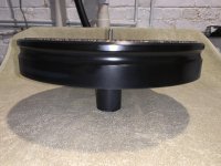
Morgan Jones' Balanced Hybrid RIAA Stage
- By niclaspa
- Tubes / Valves
- 14 Replies
I would like to build a balanced RIAA amplifier capable of an MC cartridge with 0.2 mV output. I have been looking at Allen Wright's RTP amplifiers and Morgan Jones' balanced hybrid RIAA amplifier described in his book "Valve Amplifiers" fourth edition on pages 628-645. I like MJ's design since it is quite well described and draws a lot less power than AW's designs. However, MJ's RIAA stage is designed to give 4 Vrms output with 0.3 mVrms in to match balanced digital sources. I don't use any digital sources and my line stage is designed for 250 mVrms input. Therefore, I would like to reduce the gain.
Ideally, I would like to show the schematic here, but I guess that it would violate the copyright. Hopefully, a few of you have a copy of MJ's book.
The first stage is a cascode with a transistor and an E88CC tube in each leg. MJ writes that the gain can be changed to adjust for imbalance between the channels from the cartridge by adjusting the current in the first stage and gives the following equations:
A = gm * Rl
gm = 35 * Ic
3 mA is passed in each leg of the first stage. If my math is right, I would need to reduce the gain in the first stage with a factor of 10, which would reduce the current to 0.3 mA. Would this be feasible?
I could also reduce the gain by reducing the anode resistors Rl.
Reducing the gain of the second stage is also a possibility.
Can this RIAA amplifier be successfully tweaked to suit my requirements? If so, what would the best way be?
Looking for a very nice dual opamp, for 0 to 48 volt DC power range.
It must be within these parameters:
0 to 48 volt DC ( I can regulate the voltage down using a zener diode).
Maximum 10 milliamperes total current draw.
DIP-8 package.
Minimum self noise. Good common mode noise rejection.
Usage: Amplifier and impedance buffer for piezoelectric elements wired in balance.
Why a impedance buffer is needed:
The problem with piezo guitar pickups and piezoelectric crystals is that they are not well matched to typical audio inputs. By their nature they can generate a lot of signal, but they cannot drive a 50 kilohm typical line input. The pickup needs to work into a much higher impedance, typically 1 megohm or so.
So what to people do? They go and plug a piezoelectric disks output directly into the line input of their recorder, typical impedance 50k, or the plug-in-power mic input of their recorder, typical impedance about 7k, and they start to bitch and moan that this damn thing sounds tinny. Which is does ! But they don't understand why!
The reason why these devices often sound tinny is because the piezo sensor presents its signal through a series capacitance which is small, typically 15nF or less. When wired to a normal 50 kilohm line input this forms a high-pass filter, which eliminates the bass.
Super tweeters
- Multi-Way
- 124 Replies
Been wanting to try them for a long time now just to see what the fuss is about and the fact I have two sets of speakers (a 10” two way, and 10” three way) that fall off on the top.
I’ve narrowed down to two sets that would fit the system based on sensitivity, and price (under $400/pr.)
one dipole amt 404 Not Found
– ESS Speakers USA
And a horn Fostex T96A Top Mount Horn Super Tweeter
Yes I know bats, cats, dogs……blah blah, I’m more interested in the harmonics
And also I know YouTube videos aren’t the end all but I’ve seen a couple well recorded comparisons (in/out) when in the transient/focus difference is very apparent.
One cap in series around 1uf or less will get to my target area of 14-16k, attenuation with l-pad if needed.
Just wondering if anyone had any experience with either of these particular units or thoughts on anything comparable.
One thing I’ve been wondering is how super tweeters would effect a mtm, I have all the parts gathered to build a set of 10” mtm but haven’t found time to build yet. Especially interested in the dipole with mtm……it might influence my decision more if it would help fill the vertical gap a little without compromising the narrow vertical directivity that my strange slope/high ceilings are in need of.
Also does anyone have a fr for the ess amt III ? Cant seem to find it anywhere…..they list it as up to 30khz but seems odd they don’t post any graph.
Cant really afford to buy both sets and then sell one so trying to narrow it down.
Thx 🙂
Greetings
- By powergrab
- Introductions
- 2 Replies
Hello all, George here. Just want to introduce myself as a new member. Been interested in vintage audio since before it was vintage audio. I'm sure I will find a lot of interesting information by being a member and hopefully I can contribute some. Cheers
You're gentle." "I, I don't know how I'll do. It's been awhile. And my age.." "Ah, no worries. I saw when you woke up. That first time. Let me try." Now her hand had moved down over my belly. She unbuckled by belt and opened the top of my pants. Her hand slid down further finding my ****, stimulated, but definitely not hard. She began to hold me, letting her hand move along my ****. When her thumb circled the head she said, "Oh you're cut. The men I've known at home weren't. Let me see." Now she slid down, pulling my pants with her. I was trying to relax. livesexchat.cam – live sex chat, live cam sex videos
She touched my face, feeling my salt and pepper beard. Then let her hand slide down to my chest, and down to lay atop my stomach. "I think think you're sexy. And it's cute how you're almost afraid to touch me. A this 20 year old sprite, excited to hold and inspect my currrently unimpressive old ****. She held it up, still soft in her hand, looking me over, pulling and stroking, feeling some response. Then she put my **** in her mouth and began sucking and licking at me. Finally I felt a jolt, my body jump started into the proper mode. Remembering these feelings and the proper response. My **** stiffened a bit. 1freesexchat.com – free sex chat, live sex web cams
"No really. Maybe it's not having family. Someone to look up to." "You should find someone your age." "And where did that get me?" I took her point. Still, certainly she wasn't suggesting... "I've been on my own, Making my own decisions for years now." Now she stood and walked to sit beside me. , her tongue dancing around the head of my ****, she smiled then those same teeth lightly closing on the tip. She paused a moment to say, "See, he's waking up for me." Jeannie began bobbing her head on me, blonde-red hair shining as she sucked and licked. I closed my eyes and tried to let go to the feelings. Letting my mind go blank to any thoughts that could inhibit me. Jeannie was patient and relentless. livesexcams.top – live sex cams, free sex chat, hot girls
Welcome
- By tomas74
- Introductions
- 3 Replies
Good morning,
My name is Tomasz and I'm from Poland, I'm interested in audio equipment and music. I used to build various electronic systems during my school days and for several more years.
After a 20-year break with electronics, I decided to build another amplifier, this time something called Hi-Fi equipment. I have been enjoying music amplified by the FirstWatt F5 clone for 2 months now and I want to go further and improve the parameters of this wonderful amplifier. I bow to Nelson Pass, who, despite sharing the idea, still offers advice here on the forum.
It's a pleasure to welcome all users of this Forum.
Sorry for my English.
Greetings Tomek
WTB:tango output transformer FW-20-14S
Want to buy tango output transformer singel ended FW-20-14S
Thanks
Thanks
Micromega Stage 2 modification - and incorrect info...
- By jono799
- Digital Line Level
- 60 Replies
Hi,
My first post here. I've been mildly audiophile for many years, and have done minor electronic tweaking (output stages, caps, power supplies) in the past but remain pretty clueless about the digital world.
My system (a few years old...)
-Micromega stage 2 cd player
-Audiolab 8000P+C amps
-PSB stratus silver speakers
The Micromega is either leaving or getting updated. Mine has always worked flawlessly, so I must have been among the lucky few.
Possible updates are:
-Tentlabs or D-clock (www.newclassd.com) clock, with dedicated power supply
-separate power supply for analogue section (transformer, caps and regulators, like the Tentlabs shunt regulator)
-new opamps (NE5534N originally)
Any feedback/suggestions on these? Will it improve the sound, or should I go for an other player? Rather like the sound though...
One possible show stopper: Several references online suggest the stage 2 is equipped with saa7321 converter, which appears to be of rather nice quality. I opened mine, however, and underneath the mother board i found 2x TDA1305T, as I understand a budget DAC found in Cambridge DACMagic and others.
Question remains then, how much further can I go, sonically, with this converter?
Any feedback/hints/suggestions are most appreciated!
Cheers!
Reisong A10 power switch replacement
- By Gaspar74
- Tubes / Valves
- 2 Replies
Hi. My power switch snapped on my Reisong A10. I was sent a replacement however I’ve never worked on tube Amps. Is there anything special I should know prior to going into it to replace it? I know there’s high current stores I’m sure in the Caps.
Any advice appreciated.
Any advice appreciated.
Hot-rod bluetooth speaker
Heya.
Just bought and tested Sencor SSS 6800. For the price, it actually does good job. I bought it just for the casing though, to install better components in the platform. Bad move. It is not serviceable, and I ruined it. So much for the easy way.
Now I will start from scratch.
It should be borderline compact and mobile - so not much bigger than the original Sencor. Shape can be round or somewhat boxy, but with small footprint. Sencor delivered that when put on side...
Regarding upgrade, I'm thinking two Daytons ND91-4 and three 4“ passive radiators. Box volume hanging around 3l/0.1 cu.ft.
Did anyone attempt something like that seriously?
Any interesting ideas?
Thanks.
Need Help with an Oscillating Amplifer
- By ceulrich
- Solid State
- 23 Replies
Hello All,
I am working on an amplifier with a topology very similar to the simasym amplifier that has been discussed at various times on this forum. The major difference is that this amplifier has a MOSFET output stage and operates at + / - 70V. This is a current commercial design, so I can not publish the complete schematic, but the attachment 1 shows the topology for the VAS and output stages. I blew it up by accidentally powering it up with out connecting the ground to the power supply. I have replaced all damaged components, and the amplifier seems to be in basic working order. The distortion spectrum (attachment 2) confirms that it is operating, but not very well. Attachment 3 shows a DSO photo with a 40 mVrms input, where the yellow trace is the output from the amplifier, and the green trace is that output after a 1 KHz passive notch filter, all looks well. However, attachment 4 shows the same setup but the input was increased to 70 mVrms. The oscillation during the bursts is about 11 MHz. The gate stopper resistors all measure within 2 ohms of the specified value. The propensity to oscillate decreases as the circuit warms up.
I would appreciate any help in directing me toward the source for those oscillation burst.
Thanks in advance for your help.
ceulrich
Attachments
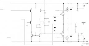
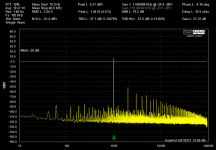
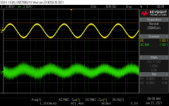
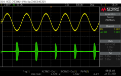
Can I use op-amp with PCM5102A?
- By Perreny
- Digital Source
- 2 Replies
Hi, folks
I'll be driving car's head unit through it's CD changer input, so not sure what load is it. Maybe there is a standard for this?
Is it possible to use op-amp with PCM5102A? In my application the load is much lower than 10k, so as a result I have much lower Vrms than it's defined in the datasheet (2.1V). So maybe it's possible to use op-amp or should I use a different DAC chip for this application then?
Anyone have ideas of it? Thank you in advance!
Naim NAP 140 offset voltage
- By jberry01
- Solid State
- 13 Replies
I have just reset the bias current to 4.5 mv across each 0.22 ohm power resistors as per acousta.org advice. Before starting the offset voltage was 7mv each channel. The initial bias was 3mv on channel 1 and practically zero on 2. On completion the offset voltage was rechecked and it had gone mad nearly 0.5 v on ch 1 and 0.2V on the other. All I did in between was set bias and disconnect power supply to measure apprx 35ma. BUT I did not turn off the amp, just pulled out the power tag to the circuit board and inserted the ammeter leads. Then put the tag back. Could this have damged anything, if so what should be checked.
Any guidance appreciated
Any guidance appreciated
Mark K's er18dxt
Here Is the design , a basic 2-way monitor using the Seas ER18RNX paper woofer ( same as In zaph's SR71 ) and the Seas 27 DXT tweeter .
The Seas ER18DXT ported two way
It's a rather new design but whats special about it is the Xover network using a second order on the tweeter , makes him play really low ... but it works .
Thing is I was going to build zaph's SR71 until I came upon this , on a meeting of fellow DIY'ers mark brought these things and they were best in show , You can see the link there .
even on zaph's own blog he considers this to be an upgrade from the SR71 , L18 builds ...
costs slightly more then the SR71 ... but probably outperforms it in any way.
your thoughts ? im seriously wondering about building these now 🙂
BC337-40BU
- By SuppersReady
- Parts
- 10 Replies
HELP!!
I've been searching for several days for 30 x BC337-40BU transistors. These are the bulk, straight leg type, not the ammo or tape versions which have splayed legs. The best result that I've obtained so far is from Arrow Electronics fro £0.81, plus £32.63 shipping, plus a highly probable £12 Customs charge. Not the best way to buy parts.
I have got some on back order from CPC which were supposed to come back into stock last week. That date has been bumped forward by another month and I anticipate that date changing again. Nobody in the UK and none of my normal American providers (Digikey, Mouser, etc) have stock of the bulk type. They are all giving expected stock dates well into 2022.
Annoyingly, two of my usual suppliers sent me the splayed leg type despite their web pages showing the straight leg types.
I have found several European suppliers who have current stock but they no longer deal with UK individuals due to Brexit (n.b. I voted to stay in!).
Does anyone have these transistors in their stock? Would anyone be willing to order them from one of the European suppliers please? I would of course cover any reasonable costs incurred.
FS 6" Misco Midrange/woofer/full range drivers
I have 20x of these interesting MISCO drivers available. No specs on them.
$100 plus shipping takes them all. make your own Line array!
$100 plus shipping takes them all. make your own Line array!
Attachments
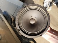
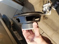

OPS asymmetry
- By Raichu
- Solid State
- 2 Replies
I am modeling an amplifier with Multisim using an EF3 OPS with 6 pairs of MJL3281A/MJL1302A driven by MJE15032/MJE15033.
With a 1KHz input signal and an output voltage of 34.6VRMS into a 4 ohm load (300WRMS), the Fourier analysis of the output node shows a THD of less than 0.0001% (9 harmonics) so the closed loop behavior seems OK.
I do a Fourier analysis of the VAS (the test node is the connection of the VAS collector to the bias spreader) to get an idea of the "correction" applied to the OPS.
With 0.2R emitter resistors, the VAS THD is 0.054% with a dominant 2nd harmonic (0.026%).
Changing the emitter resistors *only* on the PNP output devices (MJL1032A) to 0.26R (empirically determined) lowers the VAS THD substantially to 0.011%, now with a very low second harmonic. (<0.0002% = much better symmetry)
The bias is set for best THD (approx. 70mA).
I thought that something may be wrong with the models but I also tried MJL21194/MJL21193 with similar results.
Looking at the data sheets, I see that these PNP devices tend to have a higher current gain which seems to explain this.
Your thoughts and/or experiences please.
who makes "slim" amps like the one definitive technology uses?
- Class D
- 7 Replies
Hi,
hope somone know who makes the slim subwoofer amps like the one definitive technology uses?
hope somone know who makes the slim subwoofer amps like the one definitive technology uses?
[POWER AMP] Hypex NC502MP full balanced 2x350W / 8R, free shipment Europe
- By daniboun
- Vendor's Bazaar
- 0 Replies
Hi,
I selll a brand new Power amp based on the Hypex NC502MP module.
Everything is mounted with a great care
2x350/ 8 ohms
Full balanced inputs + Audio grade Filter module
Push Banana Plugs
Full alu case
Paypal Only
Free shipment to Europe only please.
Price : 550 euros
Hypex NCore NC502MP twin Channel Module
Full alu case / Sommer German cables
PSU SMPS integradted 1500W
XLR inputs full balanced
Auto sensing 100-240V mains input operation
0.5W standby operation
1.5KW Main PSU
47K Ohms Input Impedance, low output impedance
THD 0.0018%
S/N Ratio 116dB
26dB Voltage Gain
2 x 350W 8 Ohms


en majuscule
I selll a brand new Power amp based on the Hypex NC502MP module.
Everything is mounted with a great care
2x350/ 8 ohms
Full balanced inputs + Audio grade Filter module
Push Banana Plugs
Full alu case
Paypal Only
Free shipment to Europe only please.
Price : 550 euros
Hypex NCore NC502MP twin Channel Module
Full alu case / Sommer German cables
PSU SMPS integradted 1500W
XLR inputs full balanced
Auto sensing 100-240V mains input operation
0.5W standby operation
1.5KW Main PSU
47K Ohms Input Impedance, low output impedance
THD 0.0018%
S/N Ratio 116dB
26dB Voltage Gain
2 x 350W 8 Ohms
en majuscule
Old philips stereogram
- By Yoyoma
- Analogue Source
- 5 Replies
Hi all
New member here.
Ive got an old (1960s?) stereogram.
But the selector dial between phono ratio etc is stuck. Ive tried spraying wd40 but doesnt move.
Do i need to open up? And how?
Thank you all!
New member here.
Ive got an old (1960s?) stereogram.
But the selector dial between phono ratio etc is stuck. Ive tried spraying wd40 but doesnt move.
Do i need to open up? And how?
Thank you all!
Attachments
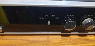
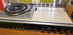
Load more
Projects by fanatics, for fanatics
Get answers and advice for everyone wanting to learn the art of audio.
Join the Community
507,666
Members
7,883,292
Messages