KICKER zx650. 4 No power transistor help

I have a Kicker zx650.4 that has no power at the ic. Several NPN, Pnp 2n4401/4403 transistors have legs have rusted or corrision where they broke the legs right off.
Q12 the silk screen is missing and was wondering which transistor is used here and in which orientation a photo would be helpful of this area.

Attachments

  • 16166726501927196652087761770381.jpg
    16166726501927196652087761770381.jpg
    1,000.6 KB · Views: 169
  • 16166726684355344505092350468611.jpg
    16166726684355344505092350468611.jpg
    998.5 KB · Views: 159

Yamaha WXAD casting to my Amp? Is their benefit?

Hi I want stream hi res Spotify through my sound system on a budget, I am looking at using the Yamaha WXAD 10 MusiCast in link below. It has a Burr-Brown DAC. I'd be connecting it to my Sony STR-DG820 home amplifier. It is a 12 year old digital HDMI amp.

Currently when I play music I have to turn on my tv and use my Chromecast ultra 4k and stream to it that way through my Sony amp. With the Yamaha WXAD musicast I won't need to use the TV and can plug it straight into amp. Would it also have better sound quality this way than using Chromecast?

I'd be streaming from my phone a Mi Max which rates as excellent when connected to an external amp in test below. I'm not sure of the best way to do this? There is a lot of rave about the raspberry Pi4 but I think that is only when using a PC.

Xiaomi Mi Max 3 review: Lab tests - display and audio quality, battery life, speaker loudness

https://www.amazon.com.au/Yamaha-WXAD-10-MusicCast-Wireless-Streaming/dp/B077Z9DWYD

Convert my blown GK bass head to donor preamp?

Resolved: Convert my blown GK bass head to donor preamp?

I have a Gallien-Krueger rb200 bass head with a blown power amp section -- the preamp section still works using the effects send.

Could anyone comment on a feasible way to use this preamp with another power amp? Pop another power amp into the chassis?

I really liked the sound of this amp compared to more modern solid-state amps and I'm pretty sore that I was unable to fix it. It was $40 so any rat-rod suggestions welcome. I believe it just needs 12v to the preamp board and send the signal out. Am I wrong?

20200507-200652.jpg

Diy atmos project, educate me

So I have 4 in wall (atmos) speakers off Amazon, built a box sealed done, but temporarily.

My goal was to buy volt 10 for atmos, BUT c19 has caused a few problems,
I did order ht10 x5 and 4 lab15 at the time.
Over a year ago from diysound ground.

So let's try and build a set

Please correct me if I am wrong / educate

My thoughts
- 10" driver maybe 8"
Speakers on list
b&c 10fcx64 or 8fcx51
Eminence kl3010cx ,
what compression driver ?
Open to other ideas,
( goal is a really nice to really really nice speaker)

Box probably like the volt 10
Will try ported and sealed box in winisd

No idea on how to make the xover stuff.


So please educate me
If there is a good post with alot of info please attach

How to Construct this Circuit?

I am working on an amp and I need to supply 3A at 6.3VDC to a 3C24 tube.
I am working from this schematic but I can't really figure out how to physically mount the diodes so they are easily wired up AND heatsink them appropriately.


I'd ideally like to use the chassis as a heatsink but I'm totally open to suggestions.

Any pictures of similar set-ups would be greatly appreciated!

Attachments

  • Screenshot 2021-07-03 130727.jpg
    Screenshot 2021-07-03 130727.jpg
    25.6 KB · Views: 299

TPA 3116 miniamp loudspeaker pop

Hi Folka I recently purchased a really cheap no-name amp from “Banggood” supposedly a TPA 3116 IC Tpa3116 class d bluetooth 5.0 hifi 2x50w stereo amplifier support usb tf card rca aux usb stick Sale - Banggood.com
…I just needed something simple for the bedroom. For the price the sound isn`t so bad but the speakers pop rather loudly on power-up . I`m afraid of eventual damage to the speakers so I`m looking to the experts for a solution. Is there a simple “filter” (spike suppression)? I could use on the line out? I once had a problem with “Hum” on a system and a simple filter solved it, so I`m thinking something similar. Can somebody help me please, I kinda like this amp. Obliged

My take on LM317 / LM337 power supply PCB

Hello,
Lots of audio equipment requires regulated, low noise power supply. Heres my attempt to design universal, quiet and relativly cheap power supply for those needs.

The idea of making this project came after seeing this thread. Basically, this is PSU part of my headphone amplifier.
Good old LM317 and LM337 regulators and half wave rectifier. Board can be powered by AC-AC wall wart or transformer. Those wall warts are cheap and easy to use as there is no contact with potentialy dangerous mains wiring.
Voltage at input passes by CLC filter. If desired, inductors can be replaced by 0-10 ohms resistor or even shorted. That would push costs even lower in tradeoff of small performance drop. Regulators are protected by D3 and D4 diodes.
Instead of using more common voltage divider to set output voltage I decided to use zener diodes. Dynamic resistance of zener diode is lower than required resistor which should result in lower output noise. By default 13V zeners yelds about +/- 14.5V at output with less than 10mV diffrence beetwen negative and positive rails. Output voltage can be changed by choosing diffrent zener diodes.

Cadj capacitors are of course present, something from range 10-47uF is recommended. There are two LEDs at both rails. Besides being indicators they run at relatively high current, providing constant load to regulators which keeps low output impedance.
Board measuers 100mm x 45mm. That means cheap PCB fabs like JLCPCB can be used. Latout PDF printed at A4 paper should be 1:1 of board size.
All required files such as schematics, BOM and gerbers are attached to post.

I'm open on any suggestions or improvements.


Attachments

Reapir SVS PC-4000 1200 Sledge Amplifier

So I managed to buy a broken SVS PC 4000 Amplifier for repair, This thing is packed with all kinds of stuff. Bluetooth, DSP, Phone App.

I managed to disassemble the plate amplifier its rather rugged/crowed with assembly plates to get to the main parts. I think I found the issues:

- Blown soft start stage.
- Blown Power Factor Correction stage.

I'm waiting on parts but the world is moving slow parts on back order, I wanted to share the parts, build quality of this amplifier is "reasonable quality".

#Configuration.

- PFC Stage.
- LLC Design. LLC
- Full Bridge amplifier (Vent Caps, IRS2092 driver)
- 2 Layer PCB.

#Parts used.

- UCC2863 PFC
- L6599AD (LLC) + LM358
- SF2008 Diode (PFC BOOST STAGE)
- HV MOSFETS P33N60E X 4 + X2 P33N60E Soft Start.
- STM32072 32-bit, m3 core.
- ADAU1718 (DSP, stereo audio codec)
- 100 V, 1200uf caps used. DC BUS. Vent
- 450V, 330uF. (High Voltage) Capxon.

# Parts to be replaced
- UCC2863 PFC
- L6599AD
- HV MOSFETS P33N60E X 4 + X2 P33N60E Soft Start.

Attachments

  • 1.jpg
    1.jpg
    153.7 KB · Views: 336
  • 2.jpg
    2.jpg
    136.1 KB · Views: 304
  • 8.jpg
    8.jpg
    124.8 KB · Views: 313
  • 4.jpg
    4.jpg
    137.5 KB · Views: 295
  • 5.jpg
    5.jpg
    75 KB · Views: 300
  • 3.jpg
    3.jpg
    140.1 KB · Views: 261
  • 6.jpg
    6.jpg
    162.8 KB · Views: 250
  • 7.jpg
    7.jpg
    109.6 KB · Views: 246

Cone midrange horn 101

I've been reading a fair amount but still can't quite get my head around it. JBL CMCD-81 was suggested to me and after reading everything I could find about it I'm now interested. Maybe more so on a CMCD-61. These, however, seem to be quite difficult to source and almost not used by hi-fi enthusiasts...so makes me wonder.

My understanding so far is 2" compression drivers have the great advantage of going up high in the treble (which I don't need), but might sound thin in the 300-500Hz region (which I do need).

Since I'm looking at 350/450 to 2500Hz for the midrange driver I'm wondering if a cone midrange horn might work. Maybe I don't need a phase plug to get to 2500Hz cleanly? What are the cone driver parameters that make it ideal for horn loading?

FWIW, it's an active system with digital crossovers and room correction. The tweeter is a Beyma TPL-150H. I was thinking of a 300Hz Tractrix or a Yuichi-type horn to try and reduce center-to-center distance to the tweeter.

Thank you!

NAD 3020 problem

I was doing ok with this today untill i came across, something i dont understand so maybe someone can assit to enlighten me


the 2 ringed vales,both are 0v and not what i expected as this is the the good channel


the issue is with the centre voltage(again @-144mv), which isnt the issue as im working my way through it, its the fact the these 2 values are not what i expected.
Q 602 B/E voltages are the wrong way round on the diagram, but couldnt change the upload before i realised.

Attachments

  • 3020 extract.jpg
    3020 extract.jpg
    498.8 KB · Views: 953

Yamaha CR 2020 power supply

Hi all,

I have performed the service bulletin modifications on mine and have a strange issue with the voltage on the collector of the negative regulator pass transistor.

I’m getting +/- 36 volts in to the board ( NB+ & NB- ) and see the raw +38v DC on the collector of the positive regulator pass transistor, as well as the expected 100hz ripple.

On the collector of the negative pass transistor I measure about 28 volts and see no ripple.

The power supply is supposed to put out +/- 25 volts and puts out +/- 26.3 V.

I recapped it as well as installing TIP41Cs in the place of the original SD234 ( TR712 and TR715) pass transistors but am a bit worried about this strange result, any ideas?

Service manual is here: https://www.vintageshifi.com/repertoire-pdf/pdf/telecharge.php?pdf=Yamaha-CR-2020-Service-Manual.pdf

Many thanks,

Attachments

  • AB909FA1-8137-4812-A63B-99E7E8F77C3D.jpeg
    AB909FA1-8137-4812-A63B-99E7E8F77C3D.jpeg
    338.8 KB · Views: 173

R-core transformer help

I recently bought a r-core 30w dual 12v transformer for a pre amplifier board that has dual 12v or 18v in. On input side there are four wires. Black and which I will be using for the 115v and red and yellow green for the 230v. Question is what wire do I use for the ground or do I just isolate the red and yellow green from shorting anything out and ground to the chassis from the iec input? On the secondary’s there are two blue and two brown wires. On the pre amplifier board it is dual 12v-0-12 or 18v-0-18. Question is what wire do I use for 0? I’ve seen it done one wire each for + and - and the other two wires for 0 i believe but I want to be very sure I wire everything correctly so that’s why I’m asking. Any help would be greatly appreciated

Attachments

  • 1C455D51-ED00-404D-B05E-06A163CC6848.jpg
    1C455D51-ED00-404D-B05E-06A163CC6848.jpg
    665.3 KB · Views: 410

6th Order Bandpass Calculations

I'm still struggling to understand 6th bandpass calculations. To convert a 4th order to a 6th order I simply put a port in the sealed enclosure, right?

But in order to calculate the port size do I treat the sealed portion of the cabinet as a separate enclosure?

e.g. 520 * 340 * 100 = 9 litres gross. A 55 * 170 port should offer me around 65Hz, right?

I'm unsure as to one enclosure's affect on the other.

Higest power supply for a dua TPA3116D2 amp

Highest power supply for a dual TPA3116D2 amp

I want to buy the 2021 Nobsound NS-15G TPA3116 amp but i do want 2x100 watt in 4 ohm or close to that since most class d amps has a max power rated at 10% thd, what is the highest i can go for, i know smsl make a 24 volt 6.75 a and nobousound a 24 6a power adapter,supply, is that enough ?

I need a good but cheep input selector (rca) for 4 units, i don't want the cheapest like this, don't like the size,shape of it, anything that can be recomended TronicXL Analogue Stereo 4-Way Input Audio Switch 3x 2x RCA Female 2x RCA Switch Switch Input Soft 1 Output 3 Input Audio Switch Loudspeaker Boxes HiFi: Amazon.de: Electronics & Photo

71MTAK-c0hL._AC_SY450_.jpg

Pioneer GM-2200 amp, DC out..

Hi,


I've got a Pioneer GM-2200 amp that I bought recently, it is not working as it should - gives DC voltage on both speaker outputs.

PCB looks ok, I can't see any burnt components.

Any pointers on how to find the fault?
It was 20 years ago since I last did any trouble shooting in electronics, so can't remember much about amps... Would appreciate some help.

Schematics and service manuals:

https://www.opelperformance.se/pioneer/GM2200.pdf
https://www.opelperformance.se/pioneer/GMH100_PIONEER.pdf

High voltage power amplifier

Hello folks, I want to build an audio power amplifier, but not for music use. The objective is to build an AC power supply.


A signal generator that can output between 40 Hz and 400 Hz will drive this amplifier, which will output up to 250 Vrms. The output will be feedback controlled to the adjusted voltage level. As you might guess, distortion and other audio quality metrics are not important. Stable voltage output, good regulation, and sustained maximum power output is important. Initially I want to achieve 1 kVA power, but with the option to increase this as needed.


I looked for circuits online, but the ones I find don't go as high voltage as I need. What kind of topology do I need to consider for this? Valve amps seem to be a nice fit for this purpose, but I neither have the experience with valves, nor can I source any valves here locally. Can you guys point to me to any relevant information on this subject? Maybe books written by the audio greats that touch on this subject so that I can buy that book?

Audio Innovations Series 500 problems

Hi

I've an old Audio Innovations Series 500 that seems to have gone wrong. I've replaced the four EL84s and three ECC83s and am waiting to get my hands on a pair of ecc88s to complete the valve upgrade programme.

However, I was surprised to find that replacing the 84s had no effect as I'd previously thought that they were shot. I'm wondering if there is some other failed component inside it. I have the schematics but I'm not very experienced with tube amps - just love the sound - and would like to ask if there's anything in particular I should check first. I read somewhere that a particular capacitor goes and that leads to tube failure but cannot remember the details..

Symptoms are as follows:


  • Humming (well it's allways done that a little bit, I guess there is a bad earth in there somewhere).
    Very very low output which distorts if you turn the volume up all the way, but stays quiet.
    Phono stage is dead quiet, no output at all.

I guess the first thing would be to test the output from the tape loop. This will provide some indicator for the phono stage.

Can anyone suggest the sorts of things I should look for? What typically fails in these amps? I can post the schematics if it would help.

Thanks

JonB

Sony CDP-30 very noisy when spinning

Hi, this morning I found a Sony CDP-30 CD-player on a fleamarket. Couldn't resist for €2,50. I want to compare it to some of my Philips players. It had been in the rain. I dried it, and when I came home I opened the case to let any damp escape. I dried it carefully with a hairdrier, not too close.
To my amazement, it came to life when I hooked it up. It wouldn't read a cd and did not spin. After I cleaned the lense, however, it does read the disk and spins. It reads the index very quickly and the display is functional and shows the disk content. So, there's actually not much wrong with it, I think.

It plays the disk, but makes a scraping noise that sounds like the spindle is not turning freely. Any suggestions?

connecting transistors to heatsink

I've been having problems for a while with a DIY power amp I've been partly responsible for building.

It's a good amp so I want to get it right. Currently NOT working.

The current spate of problems started when I lost a channel. When I picked it up to take it to my desk to start investigations I noticed it had burnt my wood floor it had got so hot.

So as part of repairing the obviously blown components (some resistors) I decided to upgrade the heatsinking by fitting a big plate of 1050 aluminium suspended between the steel chassis floor and the PCB.

I bolted the transistors down to the aluminium heat sink. Turned it on, it fizzed, popped and smoked a bit. So that wasn't ideal. The fuse had blown so probably ok.

I started again with a new board and new components as I didn't want to have to keep fixing up a board which had burnt-out once already. I thought a brand new board with brand new components would solve all my problems.

Got it all reassembled with new everything except the power supply. Turned it on, same thing, pop fizz, smoke, blown fuse.

I suspect both my boards are ok.

So the difference between when it did work and now it does not work is the way I've attached the transistors to the heat sink and I'm wondering if I've made a crucial error. I'm a general engineer rather than an electronics specialist so what I don't know about electrical engineering makes quite a long list!

In the past the transistors have been bolted to the steel amplifier case with some blue sheet between the transistor and the steel. It's worked like that for a couple of years.

With the new heat sink plate suspended inside the chassis the transistors have CPU heatsink paste instead of the blue sheet I used before.

Could it be that the blue sheet was some sort of electrical insulator which was stopping the transistors shorting on the chassis or is the difference between blue sheet and CPU paste irrelevant to my problem.

Could it be the power supply which has blown? It's the only other part not changed.

So now that Linear Audio is over, what is next?

Jan Didden's Linear Audio was a great forum for different audio authors to write and get published, however Linear Audio basically ended in 2017, I already have all the volumes but I cant stop thinking "now what?", where will the authors continue with their work? I dont believe that the JAES compares to what Linear Audio used to be which is closer to what the old Wireless World magazine used to be.

Jbl2226hpl

Hello,

I'm rather new to this forum, so first off I'd like to say how informative you've all been during my days as purely a browser, rather than the fledgling member I am now 🙂 .


OK, down to the nitty gritty.

There is a pair of 15" JBL Speakers that I'm looking into buying, they go by the name JBL2226HPL. Problem is I can't find too much information on them, I understand the 2226H is quite a revered speaker round these parts, but I'm wondering what the PL on the drivers I'm looking into stands for.

I believe the H in HPL states that it's a 8 ohm model(as it does with the 2226H model), but what does the PL mean?. Is it a lesser model in comparison to the 2226H or a better one, is it supposed to be a midbass driver or a subwoofer?.

Obviously these are all factors I need to be sure on. I found no reference to it on the JBL site, but I believe they may of come from a Bass Bin(which leads me to think they're probably a lesser model than the normal "H" variation or that they were designed specifically for sub bass usage).

Any information whatsoever would be most appreciated.

Starting to build a FHXL

I finally got some decent plywood to build FHXL cabinets, and am halfway through reading the main build thread. I'm spite of being on page 100, this is my summary of all the posts so far:

Avoid MDF- Use plywood.
About 60g of stuffing in the V and about another 60 below the driver.
You can put a wire mesh at the bottom of the V and the front panel to hold stuffing
in place.
Measure your wood, as plywood is not always the same thickness.
Use titebond 2 glue
You can use Cat5 single wires for the interior driver wiring
Rebates for panels are not needed.
Some leave the top unglued until they have stuffing sorted out.

I have some questions:
What do people use for baffle fill, and where do you get it? (I am in Canada)
Where do you get 1/2 in thick felt?
Do there have to be rebates for the drivers, or can they be mounted flush with outside front panel (I have Alpair 10p)
Any tricks for cutting the circle for the driver in the front panel.

I will post pictures once I figure out how to insert them after I upload them!

Attachments

  • IMG_20210610_190245.jpg
    IMG_20210610_190245.jpg
    626.1 KB · Views: 418
  • IMG_20210610_200613.jpg
    IMG_20210610_200613.jpg
    728.2 KB · Views: 409
  • IMG_20210613_112645.jpg
    IMG_20210613_112645.jpg
    603.5 KB · Views: 407
  • IMG_20210613_120402.jpg
    IMG_20210613_120402.jpg
    765.6 KB · Views: 395
  • IMG_20210613_115029.jpg
    IMG_20210613_115029.jpg
    674.9 KB · Views: 390
  • IMG_20210613_140241.jpg
    IMG_20210613_140241.jpg
    607 KB · Views: 125

FOR SALE: A Pair of DIY Sound Group Alpha 8 speakers

Open to offers:

649681572_thumb_a3fc36eefed5319dffb5089206a1cbb1.jpg


This URL is the offering with fully built boxes. https://web.archive.org/web/20150316033133/http://www.diysoundgroup.com/alpha-kits/minion/minion-duratex.html My purchase was earlier, when the boxes were not assembled, crossovers were unassembled, and no foam was included. Other necessaries purchased: glue, lining, binding posts, paint, boxes for (external) crossovers. Finish is black Duratex. Lining is ½” thick adhesive backed acoustical foam. Two sets of binding posts on back of cabinet, one set to each driver. Crossover is external. Crossover capacitors upgraded to SoniCap Gen 1, and Cornell Dubilier bypass capacitors added across each. Crossover schematic included. The speakers are packed in separate boxes, each 24" x 14" x 15" and 26 pounds each. Crossovers not yet packed, can go in one box, size TBD, weight should be 15 pounds. Not the best sanding or painting. Scratches on the front of the waveguides. No operational issues.

Price does not include stands or shipping.

Pickup in northeasten Pennsylvania, ZIP 18661 possible.

Thanks for looking.

Guts of a TKD potentiometer!

This is the inside of a TKD potentiometer. the surface where the wipers sweep is very shiny and smooth as you can see in pictures, even though it has gold plated contacts (looks like gold), at the tip of wipers (contact) it is not the same material as the whole wipers, they look like silver or chrome (I am not an expert in metals).Compared to the inside of an Alps potentiometer(I took one apart a few months ago)....well it looks like the TKD will last way longer than the "carbon" path of the Alps. All this reminds me the Fluke 87 and the Fluke 87III that have "carbon" path for the inputs contacts and with time people had to open the meter and "clean" it, because with a lot of use the carbon particles from trace made false contacts with other ranges in the meter and started to show crazy readings. Now the new Fluke 87V has only gold plated contacts(best)and the wipers are very soft and gentle to the contact that for sure it will last for a long, long, long time.
ok, enough of Fluke lol. Now this TKD for around $40 USD it is a very good choice to replace an old broken potentiometer. This is the TKD potentiometer that I got from Partsconnexion long time ago:
TKD 10K LOG TAPER 6R25 (2CP-601)

Attachments

  • SAM_0798.JPG
    SAM_0798.JPG
    707.9 KB · Views: 2,712
  • SAM_0799.JPG
    SAM_0799.JPG
    718.7 KB · Views: 2,657
  • SAM_0802.JPG
    SAM_0802.JPG
    718.7 KB · Views: 2,591
  • SAM_0806.JPG
    SAM_0806.JPG
    740 KB · Views: 2,695
  • SAM_0809.JPG
    SAM_0809.JPG
    744.7 KB · Views: 2,630
  • SAM_0810.JPG
    SAM_0810.JPG
    718.9 KB · Views: 1,277
  • SAM_0811.JPG
    SAM_0811.JPG
    710.4 KB · Views: 1,216
  • SAM_0813.JPG
    SAM_0813.JPG
    738.6 KB · Views: 1,264

Crown XTi Amp and Smart Wifi wall socket on & off??

Hi I just purchased a Crown XTi 800 amplifier to power my home subwoofers. This is a PA amp but is often used in home audio due to its quiet fan.

Can I use one of these smart plug below in link that uses the Australian (I am in Australia) 240V house supply wall socket. The smart plug allows wifi access with an on and off function included that can be can controlled via a phone.

Effectively I would be powering the amp on and off through the wall socket with my phone. Is this ok or perhaps harmful to the amp.
Tim

TP-Link KASA KP115 Smart Plug With Energy Monitoring - Bunnings Australia

Understanding capacitor voltage ratings AC vs DC

There are lots of poly film caps for motor run use available out in the surplus world. These look like they'd be good for tube circuits, since they're available in fairly high capacitances and they have maximum AC voltage ratings of 220VAC, 440VAC, etc. My circuits usually call for DC working voltages of 400VDC or sometimes 450VDC.

Let's say I have a 10uF film cap that's rated at 220VAC max. There is no DC working voltage stated.

Can we infer the max DC working voltage from the max 220VAC voltage printed on the capacitor? Is there a formula that can be used, or is this a complex question that requires taking into account a number of considerations?

Thanks for any insight on this.
-

PS - I found this PDF from Panasonic entitled "Permissible AC voltage corresponding to DC rated voltage":
https://industrial.panasonic.com/cdbs/www-data/pdf/RDI0000/DMI0000COL75.pdf

It suggests that the maximum AC voltage will be somewhat lower than the rated DC working voltage of a capacitor. It looks like the rated DC working voltage will be somewhere between 1.5 and 2.5 times the permissible AC voltage.

Therefore, is it safe to assume that the working DC voltage of a poly film motor run cap rated at 220VAC will be somewhere around 350VDC?
-

"Neighbour-friendly" bass solution?

I'm contemplating new bass solution for my system. The room is small, around 3x6 meters (10x20 feet), walls are rather thin and I would like not to bother neighbors but still get reasonably strong and deep bass at my listening position.

Design goals:

-Stereo (that is two cabs)
-Frequency response from 40(30 if possible)...300 Hz, where midrange takes over.
-Passive crossovers for the time being, bi-amping and active crossover later.
-More-or-less directional bass from ~30...100(preferably to ~200) Hz.
-SPL capabilities around 110 dB/m (of course, the more the merrier) for headroom. And for an occasional odd party now and then.
-Sensitivity over 90 dB/W/m.
-Size not much of an object.
-Cost is very much of an object.
-Good sounding, obviously.
-Simple construction since my tools and skills are limited.

So, after some research I've settled on U-frame and it's (pseudo)cardioid dispersion. But I have some questions:

1. Is directional bass in such small room viable? Has anyone got experience with any kind of directional bass solutions for home applications?

2. Any other simple solutions beside U-frame that do not use multiple speakers, amps and processing or sophisticated cabinets? What about regular dipoles (H-frames)?

3. Are there any guidelines (I couldn't find any) for the depth and stuffing amount for optimal performance or is it just trial-and error?

4. Drivers are the biggest problem - almost everything is just outrageously expensive here - Eminence Alpha 15 is over 114 € a piece:no:! I'm limited to ~100€ for drivers. I could maybe afford two of these, it makes 135€ with shipping. But I found some interesting dirt cheap car subs here, 35€ for two. I'm inclining to buy two pairs of them and use push-pull to reduce distortion. Opinions?

Thanks in advance,
T🙂

polarized capacitors

Hi all, reading old post and still confused. The schematic and parts list are attached. When I re-capped this in 2011, I put NP orange dips in place of C71, C72, C73 & C74 which show as polarized. (Amp has not been running except a couple of times to test.) I am having difficulty locating anything close to 0.1 mF polarized, 400V . The search bars on most suppliers sites are pretty useless, but it looks like the only polarized caps are electrolytic and they just don't come that small. There are some Aerovox .1 uf @ 400 v capacitors on Ebay. They are 50s/60s parts. would they work? I' dubious about them.

Attachments

  • pg 4.jpg
    pg 4.jpg
    529.5 KB · Views: 190
  • pg 7.jpg
    pg 7.jpg
    708.5 KB · Views: 182
  • Ebay caps.jpg
    Ebay caps.jpg
    37.8 KB · Views: 186

Designing Hifi Analog Soundsystem for Brooklyn Nightclub

Hello friends

We are on a quest to find the best solution for new hifi nightclub soundsystem. Chatting with off-the-shelf PA makers has been a bit disappointing, so figured I'd put out a call for help. I've read through many other threads, but none exactly matched our requirements.

A bit about the project:
New Brooklyn venue, focusing on Electronic Dance Music (nothing live).
The space is total about 15,000sf, with 5000sf of that being the dancefloor. We certainly need enough bass and subbass to move people's bodies, but we don't want to sacrifice warmth and intelligibility in the mids and highs. We also want to minimize signal processing, so ideally use only Drivers, HiFi Amps, and Crossovers. This is a nightclub, so extended listener comfort is more important than precision source reproduction.

Our best idea so far involves using about 20 Class AB amplifiers (1000-2000W each) to push 2-4 drivers each. Run the system around 50% load to keep ample headroom. We didnt select speakers yet, but imagining something like a Classic 4-point Dance Stacks (one in each corner of the room). Each point would have something like 2x 21", 2x 12", 4x 8" and some tweeters. These Dance Stacks could be a combination of smaller off-the-shelf speakers, or a completely custom selection of drivers and custom built cabinets.

Though we do not have extensive speaker-design knowledge, our team is sufficiently technical to fabricate high quality speaker boxes and assemble electronic components if that's what it takes.

We are open to any and all of the craziest ideas, so if you're itching to design a set of 50' exponential horns please do be in touch.

Thank you very much!

JBL GTO 627 Compliance ?

Hello, please, I need to have an idea (even if it is approximate) of the compliancy (Qts) of this speaker.

I've always wondered how a particular speaker can work efficiently in the boot or on the door of the car.

I have never seen published compliancy values (in car speakers of any brand), is it supposed to be low or high?

I have not found information on the web, can anyone here help me ?


https://www.vzdy.sk/buxus/docs/down...files/catalog_-_jbl_car_2006_(english_eu).pdf

Low-Q design – For improved bass
extension and better transient response
in infinite-baffle applications (doors and
rear package tray).

Battery Pack / Unit testing help

Hi guys. A friend gave me this JBL Charge 2+ that stopped taking a charge. When plugged in, the charging lights do not come on at all. The mini-usb charging port doesn't appear to be loose, corroded, or otherwise damaged from what I can tell. I've taken it apart and removed the battery. It's a 3.7v lithium poly pack. It has 2 black, 2 red, and 1 white wire going to the connector. I tried using my multi-meter to test across different wires, but got no results. However, since a new battery pack is around $25, so I was hoping to do some more testing before spending any money.

It occurs to me that even if the battery pack was toast, the charging lights would probably do something when the charger is attached. The fact that they don't leads me to think that perhaps it's the circuit board that has malfunctioned. Or perhaps it IS the battery pack, and the protection circuit in the battery is preventing power from reaching the unit?

I've built a number of custom bluetooth speakers, but am still lacking in a lot of knowledge. Do you guys have any suggestions of things I can test? I have a number of lithium ion 18650 batteries around, and probably still have some charging/protection circuits. I was thinking I could put together a temporary battery to test with, but am unsure about the 5 aforementioned wires on the original battery, and don't want to destroy it by cutting it apart for inspection. Any advice you can offer would be apricated.

Model: JBL Charge2+ (Looks like says M9, but the text is worn)
Battery:
Model P763098
22.2Wh Lithium Polymer
3.7v
6000mAh


Thank you for your time,
Jack

Physical Time Alignment

I'm playing DIY active crossover with a pair of PMC DB1+'s. (These are foot tall bookshelf sized speakers).

A quick estimate based on a few measurements of relative voice coil positions suggests that the in phase lobe at crossover points down at an angle of 8.5 degrees.

Since my listening position is slightly higher than the speakers, the solution is to turn the speakers upside down so that the tweeter is at the bottom and the in phase lobe then points up towards my head!

So, this has me wondering why speakers are almost universally made the wrong way up, with the tweeter at the top?

Discuss...

Help needed with repair Onkyo DX-6550 - laser seems to work, but no focus?

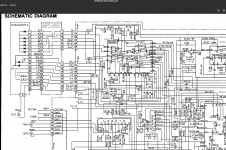
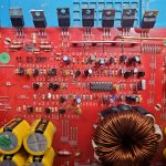
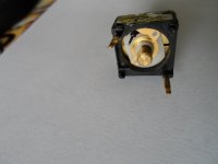
I'm trying to repair a nice Onkyo DX-6550 (sony chipset), it's built like a tank and isn't in a bad optical shape, also looks quite clean inside, so I'd really hope to repair it, but it's a tough one. The player turns on, all normal, drawer works, but CD doesn't spin. It moves the head (it's a magnetic pickup) if I manually put it away from centre, so radial movement/tracking seems ok, also focus coils move up and down (so, focus circuitry apparently working) and there IS a small red dot indicating that the laser is alive. Can't tell anything about it's health condition, though, as I can't get it to output eye pattern (disc doesn't spin). This seems to be because it can't get focus - the Focus OK signal never comes on.

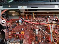
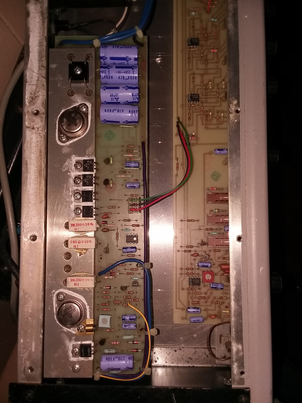
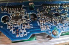
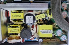
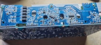
I did all the obvious checks: laser lens cleaning, power supplies all measure perfect, no obviously damaged components in sight, CD appears to be correctly secured in place (although I have no way of confirming that distance is ok, but it's not adjustable, the platter motor is direct and fixed in height. CD also turns freely if done by hand.
The platter spindle motor is working, there's no voltage present (because of no focus) but when measuring around the microprocessor, I somehow got it to suddenly start spinning (wrong speed and didn't read anything) for a second, probably I induced some wrong signal to upc which decided to let it spin for a second.
Also, tray open and close switches work fine, i checked them, but I guess that would be obvious, otherwise I think it wouldn't try to focus after loading disk.

The "Laser ON signal" sent by microprocessor is also alright - 5V for a couple of seconds and then goes down again.

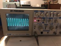
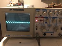
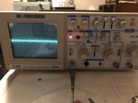
I hooked up my oscilloscope, obviously no relevant RF signal, as disc is not spinning.
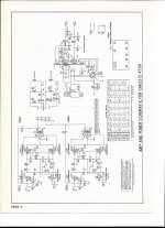
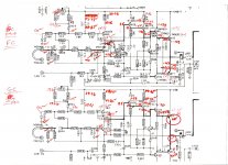
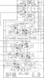
But I could see amplitude changes of focus out testpoint (goes low and then high again, with amplitudes of about 0,5V, then stays again at 0,5V offset). Lens can be seen moving well up and down and all this seems about right (in a Philips CDM service manual this is described, I think it applies to most mechanisms).

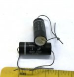
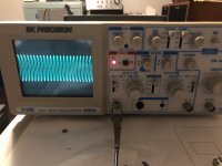
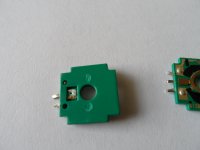
I also had a look at the Laser out, before the driver transistor it has more amplitude, clearly goes on and off (don't remember if negative, but it doesn't matter for this), after transistor (PNP) it's inverted with less amplitude change (Still around 1,3V amplitude, looks normal to me) and when laser goes off, it returns slower to original amplitude (probably because of the cap at the base of the transistor). As I didn't know if this was normal, I exchanged that cap (100uF) with a new one. No change. Also took out the driver transistor (2SA950), to test it (wouldn't measure correct in circuit), it's fine. Put it back in. Also exchanged the filter cap at the abcdef diode array to GND, it's also 100uF. No change.

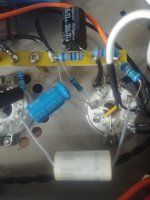
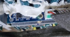
As this player has been tinkered with (the power chord is cut off, but inside someone got the leads out for testing, which made my life easier) and I don't know the history, I tried putting all adjustment trimmers to middle position (first I annotated down the values of resistance I measured, so I could get back later!), as normally this is starting point for adjustment procedure, but no luck, as it doesn't focus, all other settings are impossible.

Checked that clocks and oscillators are working - for what I could find with scope, yes. Can't figure out how to check the VCO, though. They refer to frequency counter, my DMM does have this function and I've used it in other players for similar purpose, but no display is shown here. Is it relevant for the laser unit working? Could this be the problem?

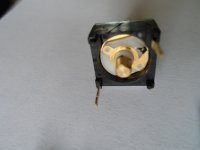
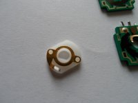
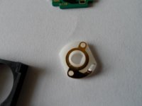
Had a look at the laser power trimmer on pickup, wasn't at any extreme position, measured it - 560 ohms. But there was a black mark and the thing wasn't adjusted to it, was slightly more to the left (more resistance), I tried putting to black mark - no difference. Put it back where it was.

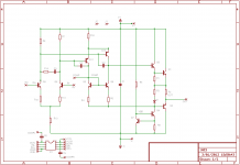
Now a couple of things I find strange (but I'm still struggling with understanding the whole way of functioning of the APC circuit, photo diode array and everything, so maybe they are normal):

- measured 2,64V DC over the two parallel 33 ohm resistors at laser driver transistor (emitter), that would translate to 162mA being drawn from transistor (which only powers the laser diode, obviously), does that mean laser is being driven with that high of a current, adjusted by APC?!?! Is this an indication of a dying laser? Or malfunction of APC? Or am I doing the measurement/maths wrong?

- Monitor photo diode (PD) of OPC circuit outputs -7,62V when laser is on (0V otherwise), I found that strange, if the whole circuit only works with +-5V power rails??? I'm measuring at anode of diode, where it is connected to laser power trimmer.

-At the outputs of the photo diode array abcdef (inputs of RF amp), I can only see very small amplitude signals, is that normal? If measured with DMM, they change in polarity when laser is ON, for example: -3mV goes to +3mV and then back, when laser is off and it stops trying to focus.

So, resuming: although the laser looks ok to me (I look at it through mobile phone, always, for safety), looks similar to what I've seen in other players, could it be weak? As I've measured that strange 162mA... but maybe wrong way of measuring.
Could the focus circuitry be bad, although it seems to work?
Could the RF amp (CXA1081S) be bad, so not amplifying photo diode array output well?
Could it be the VCO, not working?
Could the APC for laser not be working, although components measure ok? Maybe the photo diode? Those -7,6V...
Could there be some weird problem in the surrounding circuitry, not allowing focus circuit to have correct functioning? I'm referring to the circuit with all the adjustment trimmers.
Last idea I have: maybe the focus and tracking driver chip is defective, although it seems to work?
Maybe even some strange mechanical problem I haven't spotted which makes the lens not being at right distance of disc? I had this with a B&O player which came back to life after adjusting disc height. But this one has no adjustment.

Please, share your thoughts, I'm kind of lost here... thanks!

Attachments

  • onkyodx6550.png
    onkyodx6550.png
    681 KB · Views: 199

Need help Trouble shooting Crossover on a ceiling speaker

Hey guys, im trying to figure out why my ceiling speaker has no output from the woofer or tweeter. I cannot seem to get a resistance at the main input speaker terminals but i did measure resistance at the woofer and at the tweeter wires individually and everything seems to be OK. Ive done a little bit of troubleshooting on my own and when i was probing the negative terminal in combination with any component (PTC fuse, the capacitor, and any of the resistors) on the crossover i get no continuity what so ever. However, when i take the same model speaker but a fully working one and i probe the negative terminal in combination with any of the components listed above i get continuity. What section of the crossover would cause a no output condition? I've been toying with the fact that its the PTC resettable fuse but i am unsure if its used to only protect the tweeter or if its used to protect the entire design.

Rotel RDG-1520

Hello Forum

I'm posting this thread because I would like to know if any of you are familiar with the "Rotel gateway player" (RDG1520).

If so - have you been able to receive dab+ stations on the player.

According to "Digicomparison.com" it should be compatible with dab+"
Unfortunately I have never been able to receive any dab+ - and have only seen the message "No service" in the units display. It has dab - band III - and I think that "Digicomparison" because of that have made the conclusion that it then should be able to receive dab+ /but right now I doubt that this is correct.

BR Benny

LF03 discrete opamp

A sneak peek at the topology and preliminary simulation results for a new discrete opamp design called the LF03 - the 3rd in the Lake-Forest series of discrete opamps. The 1st was the single-opamp LF01 (whose Class-A output stage is also used by the LF03), and the 2nd design (LF02) was basically a dual LF01 which hasn't been prototyped yet. This is the 3rd, and the first fully-discrete unit. It borrows some concepts from the AD797 - I dropped the folded cascode of the AD797 in favour of a common-emitter PNP differential amp (similar to the Melcor 1731) for the VAS, which drives a Class-A driver biased at nearly constant current, followed by a Class-A push-pull output stage (borrowed from the LF01). The input LTP is generic, topologically similar to the Melcor 1731 and various other "classic" opamps. The compensation schema is a combination of that used in the Melcor 1731 and AD797B.

I've not included the component values, which are still evolving - though the topology is frozen and the layout has been completed and sent for panelization and PCB fabrication. The simulated LTSpice THD20 plot shows the output FFT of a non-inverting unity-gain buffer at 20 KHz, 4V amplitude into 600 ohms. As can be seen, H2 is down at about -100 dB and is the dominant distortion component, similar to OPA627 and AD797B (from where the floating current-mirror in the VAS has been borrowed from).

Typical uses are expected to be line-level stuff: I/V converters, gain stages, preamps, tone stages, active filters, headphone amps, etc. Basically, it can substitute most monolithic DIP8 dual opamps at almost any location where a Burson/OPA-Earth opamp can be used.

Attachments

  • lf03_sch.png
    lf03_sch.png
    20.7 KB · Views: 2,949
  • lf03_20k_4v_600r_fft.jpg
    lf03_20k_4v_600r_fft.jpg
    279.6 KB · Views: 2,934

1st time going active- what proven diy 2 way for sub design

I am looking for a proven design 2 way diy active xover for use with my Nomex 164 and a sub which I will build using a Peerless 830668 and Lm3886 IC chipamp. I have googled and have found some schematics, but I do not want to waste time. As this will be my first active experience, I appeal to anyone that has actually built one from scratch. Tks in advance for the schematics.

Oscilloscope distorted waveform at edges

Attachments

  • 1 kHz 1M.jpg
    1 kHz 1M.jpg
    469.1 KB · Views: 350
  • 1 kHz 10M.jpg
    1 kHz 10M.jpg
    453.6 KB · Views: 299
  • 10 kHz 1M.jpg
    10 kHz 1M.jpg
    493.7 KB · Views: 291
  • 10 kHz 10M.jpg
    10 kHz 10M.jpg
    460.7 KB · Views: 292

Build time to adjust sound on Sansui Silcron Speakers.

I have a pair of original, Australian made Sansui Silcron Monitor speakers.

Three way, 12" woofer, 5" mid, & 4" tweeter.
Rather than using a dedicated crossover, the tweeters have electrolytic caps in the wiring on the positive wire just before the tweeter + terminal.

They're not cutting edge, but for the right owner they're reasonably dynamic and listenable.

I'm finding they're a little hissy during vocals where "s" is involved

Is it worth experimenting with a resister to control the tweeter and where would I include it in the circuit?

Or, should I re[lace the cap with poly?

Don't want to over capitalise but would love to improve the sound.

Cheers

Attachments

  • silcron 4.jpg
    silcron 4.jpg
    297.9 KB · Views: 236
  • silcron 1.jpg
    silcron 1.jpg
    503.8 KB · Views: 253
  • silcron 2.jpg
    silcron 2.jpg
    399.5 KB · Views: 229

TPA 3116D2 Sub Amp

I'm trying to build a very basic 2-channel subwoofer amp from spare parts I have lying around.

I have a stereo TPA 3116D2 board TPA3116D2 Dual Channel Stereo Digital Audio Power Amplifier W6A6 Board C2T2 | eBayAnd a transformer from Bose Companion 5 Power Supplies, Block Diagram - Bose Companion 5 Service Manual [Page 36] | ManualsLib

Questions: (1) How many volts is the transformer? (2) What else do I need?


https://www.ebay.co.uk/itm/353599420814?hash=item52542af98e:g:mqUAAOSwZrhhA9Ph

Dynaudio sub500

I need some information about the Dynaudio Sub500.
Inside connection cable broke, 6 wires from the front to the amplifier board.
The wires are soldered to the board, I think there have been a connector from the factory but now it's soldered. A few wires are loose from this board.
So I need to know which color wire goes where on the board.
It should be fit to the upper corner on the amplifier board.
Thanks in advance for your reply

Another noob needing help with his SSE Build

I have a little experience building diy audio kits but this SSE build will be my first time building a tube amp. I populated the board over the last week or so in my free time but I realized yesterday that I made a mistake.

I wanted to have the board underneath the chassis with the tubes on the opposite side facing up. Unfortunately I put all the components on the top side except for the tube sockets on the other side. Is there a reason why the tube sockets and resistors should be on the same side if doing a reverse layout. Also is it still possible to mount the board the way I have it with just the tube sockets on the opposite side facing up?

Here are some photos.

Attachments

  • PXL_20210711_145011940.jpg
    PXL_20210711_145011940.jpg
    971.2 KB · Views: 302
  • PXL_20210711_145006011.jpg
    PXL_20210711_145006011.jpg
    976.5 KB · Views: 300

Upgraded Single Board PCM1794 NOS DDDAC

With the help of many contributors to the http://www.diyaudio.com/forums/digi...dac-pcm1794-waveio-usb-input.html#post3252373 thread I implemented a series of upgrades to Doede’s DDDAC which resulted in my single board DDDAC-Buffer-Cinemags sounding far better than I thought ever possible by any DAC. Doede’s brilliant NOS PCM1794 design and the optimized operating parameters are the foundation on which these upgrades are applied.

I reported my upgrades on the main forum thread but they are so scattered that I decided to put them all together here with even more explanation and pictures. Everything except the buffer applies to multiple DDDAC stacks as well.

The following is a summary list of the upgrades in order of sq improvement/cost:

1. Digital Sources. I have a WaveIO with a Belleson Vreg and simple reclocker which I am very happy with. I plan to try a BBB with an Acko reclocker because of the many posts that the rpi and BBB sound even better. Clean digital source stream is a must.
2. ½ clock delay circuit. If you have a blue Main Board then you already have this. If you have a red Main Board then you MUST add a 2 chip circuit which provides this I2S Data delay. Four out of 4 persons who have done this report a major improvement in sq. Music and voices sound more coherent and real. See group buy for 2 chip PCB at end of thread.
3. Analog 8VDC power supply. I use a Salas Shunt power supply. Others have had great results from Tent Shunt supplies. A Belleson series Vreg can also be used. This increases the musical energy and dynamics as well as more detail. This power supply may partially offset the need for a buffer.
4. CCS. The standard circuit for pin 20 is a 6K resistor to ground. Changing the resistor to a premium type provides very little improvement in sq. Single JFET CCS circuits using the 2SK246Y or the 2SK208 “O” or “R” sound more “musically exciting” and increase detail. When changing back from a CCS to the 6K resistor on pin 20 the sound became a bit compressed with less detail by comparison. Why does the CCS circuit sound so much better than a resistor? I've concluded that it actually makes the PCM1794 DAC chips sound better. Both JFETS also have a low temperature coefficient. Toshiba officially lists the 2SK208 as the replacement for the discontinued 2SK246. They sound the same to me. See Assembly instructions for CCS circuit board. http://www.diyaudio.com/forums/digi...e-board-pcm1794-nos-dddac-37.html#post4229210
5. Buffer. A single board DDDAC is inadequate to drive the DAC output through a transformer without sounding a bit thin and weak in the bass. The music sounded pleasant and polite but I was left wanting a more real musical experience. Four or more DAC boards can properly drive the signal through a transformer. The forum consensus suggests that a partially upgraded single board DAC sounds better in some ways than a standard 4 DAC stack. A fully modded 4+ DAC stack sounds incredible but is expensive and tall and requires a huge power supply. A fully modded single board DAC with an output buffer is the alternative. The buffer increases the musical authority, bass and detail through the Cinemags. The Cinemags no longer sound weak or thin. The downside of the buffer is that it requires +12V and -12V power supplies, 4 matched pairs of BF862 SMD JFETS, and a PCB. This post has more explanation of the Buffer: http://www.diyaudio.com/forums/digi...e-board-pcm1794-nos-dddac-11.html#post4163372 Direct feed NOT recommended as discussed in this post: http://www.diyaudio.com/forums/digi...e-board-pcm1794-nos-dddac-18.html#post4173717 See GB for CCS circuit board.
6. Digital Vreg. I use Belleson SPM 3.3V regulators on the PCM1794 digital circuits. Others report using the Tent shunt regulator with success. Even if the standard LF33 Vregs are not replaced, the digital caps should still be OSCONs. I also use Belleson SPM 5V regulators with additional caps on the main board. The sound improvement from the Belleson’s and OSCONs was modest, but the music sounded more “settled down” and the details seemed to have much fewer unnatural artifacts.
7. Rload Resistors. A premium resistor like the tantalums, Rhopoints, TX2575, or Susumu SMD sounds clearer than the standard Dale or the PRP. I use tantalums and Susumu’s on my two DDDACs. I also tried 120 ohm tantalum resistors which didn’t sound quite as good as the 135 (2x270) ohm Tantalums. Doede tested many different resistor values and 133/number of DAC boards is the sweet spot for sq. I tried 135 (2X270) ohm Susumu RG's with success. See http://www.diyaudio.com/forums/digi...e-board-pcm1794-nos-dddac-32.html#post4202948
8. Cinemag Load. Having a load of 8K-15K on the outputs of the Cinemags, including the preamp input resistor, sounds best. Having a 220k ohm preamp load sounded unstable in the higher frequencies to me. Adding extra resistance in the output requires high quality resistors. I use two LDRs in series set at 11Kohms. Dwjames and I tested Wima FKP 3 film caps on the Cinemag outputs and found that 150pf brings the musical detail into proper focus. Higher capacitor values start to collapse the sound stage.

I will add posts to this thread which provide more details on each of the above items. In order to keep this thread from getting “scattered” please confine comments to the buffer only. All other topics should be posted on the http://www.diyaudio.com/forums/digi...dac-pcm1794-waveio-usb-input.html#post3252373 thread because they are of more general interest. You can also send me a PM if you wish.

Reisong A20 - faulty capacitor

Hello everyone- I am new here and would like to get some advice about my tube amp where one of the capacitors for the power tube has starting blowing smoke and I plan to have replaced. I would also like to upgrade the caps to the driver tube as well but would like to do this one at a time. I've included a photo of the driver socket (it's the one on the right side of the close up photo) and its associated caps. I was hoping someone could tell me which cap out of this trio would make the most difference in terms of potential sonic improvement. I've decided on using Miflex caps and would welcome any suggestions on which values for the caps I should be aiming for to try to avoid another blowout. While I've been an hi-fi enthusiast for over 15 years- I've actually never worked on any of my equipment before and am having a friend who works with electronics help me with this project though he is not into audio himself. If I am posting in the wrong place or if more information is needed please do let me know where I should be or what more information is needed. Any help is greatly appreciated.

Attachments

  • 0728211836.jpg
    0728211836.jpg
    328.8 KB · Views: 183
  • 0728211924.jpg
    0728211924.jpg
    523.1 KB · Views: 183

Use and mods to Analog Metric SR50 Shunt Regulator

Over the last few months I have been using and tweaking this for a 5v 1A shunt regulated supply for a Raspberry Pi based music server, http://http://www.analogmetric.com/goods.php?id=2211 and though I would share my findings with the forum members.

First of all I need to make clear that a lot of my findings have been based on simulated Spice CAD results (NI Multisim) and my test equipment is very basic, oscilloscope, frequency counter, dvm. Now this may ruffle a few feathers, but all measurements are comparative and the reason in sharing my findings is to offer them up to my peers for review and criticism even! Hopefully, someone with better equipment might try a few ideas and make some real world measurements? Glad to get that out of the way!

Now this kit gives excellent value for money and is of good quality, but it will not provided 1A @ 5v and it will only provide around 89dB of PSRR in its original form. However, a couple of simple mods will give the required current and significantly improve the PSRR. If you follow the link below it will give the schematic for reference.

Mod 1 - to get 1A at 5v simply replace Q2 with a Darlington type, I used a TIP137, which is a pin for pin replacement for the MJ15031. The Darlington increases the vbe of Q2 to allow Q1 to turn on enough to enable the current source at this level. This mod also improves PSRR due probably to the higher hfe of the Darlington. R1 needs to be around 0.5Ohm to give 1A out.

Mod 2 - to improve PSRR even further, disconnect R4 (10k) from the junction of R3, D1 and Q3 and connect it directly to the +ve regulator output, i.e. collector of Q2. This is in line with the typical applications part of the TL431 datasheet. The pot will have to be adjusted to get the right Vout of 5v, but it is within its adjustment range. This mod increases PSRR to almost 140dB up to around 20KHz and from there it deteriorates back to around 88dB at 600KHz

There are further mods that can be carried out to improve PSRR even further over a wider bandwidth, but they require more "surgery". If this thread generates any interest then I will be happy to share those too.

I have used this modified regulator for a few months and can report that it has been rock solid and quiet and the sound quality improved with every mod that I tried.

Your feedback would be appreciated ladies and gents!

Attachments

For people in the EU: Cheap Toroidal Power Transformers on eBay

230V 2x24V 1000VA for 50.93 EUR.
230V 2x24V 3000VA for 104.43 EUR.

6.90 EUR shipping to Germany.

I ordered two of the 1000VA transformers for my Sony VFET amp and I can say they look great. Haven't hooked them up yet though.

Ringkerntransformator 230 V | 2 x 24 V | 1000 VA | -A2- Trafo Transformator | eBay

Ringkerntransformator 230 V | 2 x 24 V | 3000 VA | -A1- Trafo Transformator | eBay

--Manfred

Akai AP-007 or Technics SL-5

Hi I own the Akai for some 40 years but now the synchronous motor driving the switch on/off mechanism failed. I don’t think I’ll be able to find a replacement with the same specs and shaft (D-shape). I can scrap it and start using the Technics or modify the Akai, make it fully manual. Please advise, would this modification be worth it or is the SL-5 in the same range or maybe even better? I guess you’re going to say it depends on the cartridge/stylus but suppose I’ll make sure those are in the same league; what would you say?
The rubber ‘feet’ of the Akai are fairly worn btw.

The sound of EL84 vs EL86....

I've built up all 3 of George's boards, and finished the SSE. And an remarkable little amp she is, I listen to her daily.
I was planning on doing the 45 amp next, but lack of money for the transformers has put that on hold. So because I have a pair of old Sansui 1000 tube receiver output transformers, I figured I'd build the SPP next. It seems a no brainer to use these outputs with the EL86 tube, but my question is this. Does an EL86 amp sound as good as an EL84 amp? Any thoughts?

Steady thumping noise in preamp

Unit: MFA Luminescence preamp. Separate power supply, tube regulation, octal tubes, decoupling electrolytic on each tube. Just replaced large coupling caps with Dynamicaps 4 mf

Problem: Not motorboating in the classic sense, but a steady thump, not heavy, short, like a soft rim shot in a snare drum. If I were playing LPs, I'd say it's a steady once-per-second or so sound of a stuck record. But I'm playing CDs. The CD plays, the music is there, but so is the thump. It's much louder on one side than on the other. I'm assuming the cause is on the loud side and is being picked up on the other.

I'm thinking maybe it's a defective Dynamicap (or solder joint, but I'm not there to check it) or a decoupling cap. I'm assuming it's not the power supply because of the disparity between the two channels. Thoughts?

How to sort classic records

Hi friends

I inherited (a gift from my father who luckily is still doing very well 🙂 ) a quite big collection of vinyl classical records (close to 4 m of records), all sort of—from baroque to modern, chamber, solo, orchestral, symphonies, operas, and a few exotic things...

Classic records are quite complicated, as many are just a "work" (like a piano-concert etc.) while many are compilations of something (great sonatas, Schubert's piano-sonatas 1,3,8 etc.), and the interprets are "never" the same—the conductor, soloists, orchestra are very often interchanging.

We (my wife and I) haven't found a common ground as to how to organize it, and settled on the simplest and least clear structure: alphabetical by composer, which causes "problems" with records where a certain interpret is playing various pieces...

What are your recommendations for a clever structure?

Thank you!

Optimal lm317 layout

Hi guys lately ive been obsessed with squeezing the most out of my lm317 supply. My question now is how the layout should be around the adjust pin, involving the variable resistor and the bypass cap. The layout for my board is such that the two components cant be equal distance from the adjust pin. So my question is should the resistor be closer or the cap closer to the adust pin, and why?
Projects by fanatics, for fanatics
Get answers and advice for everyone wanting to learn the art of audio.
Join the Community
507,666
Members
7,883,375
Messages

Filter

Forum Statistics

Threads
405,990
Messages
7,883,375
Members
507,666
Latest member
Fpa420