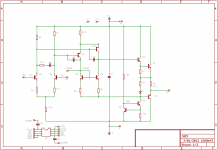
A sneak peek at the topology and preliminary simulation results for a new discrete opamp design called the LF03 - the 3rd in the Lake-Forest series of discrete opamps. The 1st was the single-opamp LF01 (whose Class-A output stage is also used by the LF03), and the 2nd design (LF02) was basically a dual LF01 which hasn't been prototyped yet. This is the 3rd, and the first fully-discrete unit. It borrows some concepts from the AD797 - I dropped the folded cascode of the AD797 in favour of a common-emitter PNP differential amp (similar to the Melcor 1731) for the VAS, which drives a Class-A driver biased at nearly constant current, followed by a Class-A push-pull output stage (borrowed from the LF01). The input LTP is generic, topologically similar to the Melcor 1731 and various other "classic" opamps. The compensation schema is a combination of that used in the Melcor 1731 and AD797B.
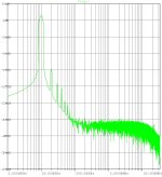
I've not included the component values, which are still evolving - though the topology is frozen and the layout has been completed and sent for panelization and PCB fabrication. The simulated LTSpice THD20 plot shows the output FFT of a non-inverting unity-gain buffer at 20 KHz, 4V amplitude into 600 ohms. As can be seen, H2 is down at about -100 dB and is the dominant distortion component, similar to OPA627 and AD797B (from where the floating current-mirror in the VAS has been borrowed from).
Typical uses are expected to be line-level stuff: I/V converters, gain stages, preamps, tone stages, active filters, headphone amps, etc. Basically, it can substitute most monolithic DIP8 dual opamps at almost any location where a Burson/OPA-Earth opamp can be used.
Attachments
Last edited:
The first prototype LF03 is built, functional, and sounds very good as the line amplifier in a Marantz DV-4400 DVD player.
Here's the present BoM - some values will evolve over the next few prototypes:
Q1: 2sc1845F
Q2: 2sa733 (not great, but it's only an emitter follower here)
Q3..Q8: 2sc1845F
Q10..Q11: 2sa992E
D1: 1N4148
R1: 1k
R2: 6.8R
R3: 22R
R4, R6: 1k
R5: 33k
R7, R9: 33k
R8: 150R
R10: 1k
R11, R12: 1k
R13: 82k
R14: 150R
C1: 6.8nF ERO KC1850 polycarbonate film/foil
C3: 680pF ERO KC1850 polycarbonate film/foil
C2, C4: 15pF Philips C0G ceramic plate type
C5: (omitted in first prototype, typically 22 to 100 pF).
Last edited:
Where is C5 located?
Why a relatively low hFE grading for the input pair?
Would it be worth "tuning" the LTP tail current to suit different uses?
R13=82k seems to suggest lowest noise performance is aimed at quite high source impedance.
C5 is located on the base PCB, i.e. the one where the DIP8 pins are soldered and the individual opamp daughter-boards are mounted. There's not much clearance or space at that location, and the pitch is 2.5mm, but it's enough for a pair of C0G axials or ceramic plate-type caps to be mounted. The DIP8 pinout doesn't include compensation for a dual-opamp (obviously, shortage of pins), so this is the closest that can be managed.
No problem using higher hFE grades for the input pair, but notice the relatively large emitter degeneration resistor of 1k. There won't be much difference in degenerated gain regardless of the gain grade - it will remain around 33k/1k = 33.
Yes, tail-current can be tuned (say 47k), but it needs small biasing mods to the R7/R9 values or better still, one diode drop from the upper rail combined with smaller R7/R9 values (~10k). The c1845 has pretty good noise performance even at ~50uA, though it's optimal around 0.5 to 1 mA.
Looks very interesting. What are the dimensions of the base PCB? It looks considerably larger than a chip and might not fit into many existing PCB's with tight clearances. Could it be made more compact if the daughter boards were reversed with components mounted on the outside surfaces with an insulator between the two boards?
Supply voltage?
Can you compare the sound to any existing chips?
Peace,
Tom E
Supply voltage?
Can you compare the sound to any existing chips?
Peace,
Tom E
Looks very interesting. What are the dimensions of the base PCB? It looks considerably larger than a chip and might not fit into many existing PCB's with tight clearances. Could it be made more compact if the daughter boards were reversed with components mounted on the outside surfaces with an insulator between the two boards?
Supply voltage?
Can you compare the sound to any existing chips?
Thanks, Tom. The dimensions of the base PCB are ~19mm x 17mm (~3/4" x 11/16") and the height, including pins, of the entire assembly is 40mm (~1 9/16"). It's larger than a DIP-8 chip - whether it will fit depends on clearances to adjacent parts. It's possible to use one or more DIP-8 sockets as spacers to raise the assembly above adjacent parts if there's interference.
I thought about the reversed (back-to-back) assembly of the daughter boards (which is used presently on the Burson HD discretes), and it slightly complicates the assembly on the base PCB. In principle, it is possible, but requires a fresh base PCB layout (or something like a perf-board).
Supply voltages are +/- 9..15V on the first prototype. I got some initial feedback that there's interest in using it in PCI sound cards, which often run the analog section on regulated +/- 5V. I'll be testing a mod (requires one track cut and one diode mounted on the solder side, or no track cuts but two diodes to be squeezed into the component side) that will allow operation on a wider range of supplies, say +/- 5..18V if possible.
At +/- 15V, the GBW (simulated) is ~10 MHz (not too fast, but adequate). I tested it in a Marantz DV-4400 DVD player in place of the stock JRC-something opamp. The design of the Marantz is not optimal, in that it uses an SMPS located less than 2" away for all rails, including the analog rails. Nevertheless, the improvements in audible sonics are immediately apparent. It is darker, more transparent, has greater detail and with improved dynamics and imaging.
I'll be testing a pair in a much better-designed Marantz CD-53/63 shortly.
Higher hFE to reduce the input bias currents, significantly.
Not to change the amplifying characteristics.
The DC beta of the 2sc1845F devices that I'm using are in the range of 400-600, but mostly clustered around 400. With a tail current of ~180 uA at +/- 15V rails, it works out to 90 uA per device, and therefore Ibq ~= 225 nA per device. Even with a 100k bias resistor from base to ground, that's only 22.5 mV across the bias resistor. At typical rails of +/- 9V, the bias currents will be approximately halved.
I can hand-select a few 2sc1845F with DC beta of ~600 if needed. Another alternative is the high-beta Toshiba 2sc3112 with typical DC beta around 1500, but it will have a lower Early voltage.
Last edited:
Can you compare the sound to any existing chips?
I just did a comparative audition of a) a modified 2nd-prototype LF03 dual-discrete against b) 2x OPA627AU mounted on a dual SOIC-8 to DIP-8 adapter. Both were plugged into the same Marantz DV-4400 DVD player - the weak link in the whole setup.
Nevertheless, there are immediate audible differences that are apparent:
The LF03's Class-A push-pull output stage contributes to a smoother, full-bodied, aspirated and airy presentation.
The OPA627AU has excellent micro-detail and dynamics, but it sounds a bit discontinuous, grainy, edgy and jagged - it lacks the smoothness and continuity of the LF03. This could be due to the JFET input stage of the OPA627, or the Class-AB output stage, or even the less than optimal bypassing on the Marantz DV-4400.
I'll repeat this test later with a better-designed source, maybe a Marantz CD-4000 or similar.
(The modified 2nd-prototype LF03 uses an additional diode and alterations to the values of some passives to allow unity-gain stable operation across a wider range of rail voltages: +/-4V to +/-18V, compared to the 1st prototype, which was restricted to +/-9V to +/-15V. The sonics of both prototypes are very similar at around +/- 12V).
Are you going to offer boards for this? I have an interest for a specific application.
Bare board sets (2 + 1 PCBs) and kits (PCBs + parts) are available. Please PM me or email me at siva dot chander at gmail dot com.
(Note that there are changes to the schematic that require a track cut, one additional reference diode per channel, and some changes to component values. These changes allow operation over a wider range of rail voltages (+/- 3V to +/- 18V) than the original circuit, and a consequent reduction in GBW product at low rail voltages.)
")
Update: SMD LF03 versions have been prototyped and are fully functional - I'm evaluating the audible sonics, which seem to be similar to the previous through-hole version, the LF03c. The SMD single, the LF03s has been tested working in a MyRef Rev C in place of the LM318 monolithic opamp.
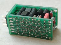
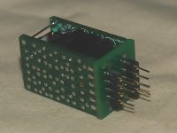
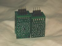
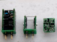
Pics of the different versions of the LF03, including the latest SMD version(s) - from left: the LF03c (through-hole dual), LF03d (SMD dual, derived from the LF03c topology) and LF03s (SMD single, which is the same as one channel of the LF03d and shares the same PCB):
Pics of the different versions of the LF03, including the latest SMD version(s) - from left: the LF03c (through-hole dual), LF03d (SMD dual, derived from the LF03c topology) and LF03s (SMD single, which is the same as one channel of the LF03d and shares the same PCB):
Attachments
Link to posting on the vendor's forum offering the LF03s (DIP8 single) and LF03d (DIP8 dual):
http://www.diyaudio.com/forums/vend...p8-opamp-myref-rev-c-similar.html#post3644382
(These are general-purpose bipolar-input opamp upgrades, and have been widely used in I/V, line amplification and other small-signal and line-level applications, in addition to the LM318 upgrade in the MyRef Rev C mentioned in the posting. The most common application for the dual version is CDP/DVP/DAC line-amp upgrades.)
It would be interesting to see some Samuel Groner style tests of these. The last time I was playing with discrete folded cascode topologies in simulation, results were rather disappointing.
The LF03 is not a folded cascode, though I've built another DIP8 single (LF05) using a folded cascode - which sounds OK but not as detailed and well-defined as the LF03, which uses a base-driven differential VAS with a floating current-mirror - a bit like a bipolar-input Kaneda on steroids.
For Class-A discrete opamps, the measured distortion can be misleading - they often sound better than the numbers may indicate. Conversely, Class-AB monolithics often sound much worse than the distortion numbers indicate - the LM4562 being the poster child.
- Home
- Source & Line
- Analog Line Level
- LF03 discrete opamp