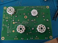
I have a little experience building diy audio kits but this SSE build will be my first time building a tube amp. I populated the board over the last week or so in my free time but I realized yesterday that I made a mistake.
I wanted to have the board underneath the chassis with the tubes on the opposite side facing up. Unfortunately I put all the components on the top side except for the tube sockets on the other side. Is there a reason why the tube sockets and resistors should be on the same side if doing a reverse layout. Also is it still possible to mount the board the way I have it with just the tube sockets on the opposite side facing up?
Here are some photos.
Attachments
Also, to make sure I haven't made any major mistakes in ordering the right parts.
Power transformer- Edcor XPWR035
OT- Edcor CXSE25-5K
Choke-hammond 159Q
I still need recommendations for a motor run cap, the iec with fuse part number, and the switches. Plus I have to order some binding posts.
Any concerns over the parts I've chosen?
Power transformer- Edcor XPWR035
OT- Edcor CXSE25-5K
Choke-hammond 159Q
I still need recommendations for a motor run cap, the iec with fuse part number, and the switches. Plus I have to order some binding posts.
Any concerns over the parts I've chosen?
Last edited:
The tube sockets must be mounted on the correct side. This is because the pin layout for the tubes is not symmetric.
When the tube socket is mounted on the correct side, you will be able to look at the solder side and count the pins clockwise from pin #1 onward. The numbering starts clockwise after the gap or key. This means that your tube sockets
are mounted on the wrong side of the board. If you have some scrap pcbs, practice desoldering some components
before attempting to remove the sockets.
Components with only two leads could be mounted on either side of a board, if the correct leads are in the correct holes.
However there may be mechanical problems mounting components on the wrong side of the board, even if they will work electrically. So, always assemble a board as originally intended.
This SSE thread has some photos of the assembled board.
Birk's SSE Build Thread
Last edited:
Ah okay that makes perfect sense, I should have thought about this beforehand. I'll desolder them soon, thankfully I have a larger solder desoldering pump.
Would it be best to just buy new tube sockets? I think I read it's very difficult to desolder them without damaging them.
Would it be best to just buy new tube sockets? I think I read it's very difficult to desolder them without damaging them.
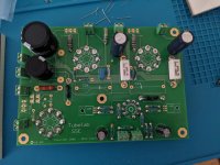
I ended up just cutting the leads on the tube sockets and desoldering it that way. I tried doing it the other way but I used too much solder initially and it would have been too time consuming.
All of the sockets are now desoldered and there doesn't appear to be any damage to the board. I'm going to order some more tube sockets today.
On another note, I realized there are a few parts that seem to be omitted from the guide on tubelab. Mainly the current inrush capacitors, cl-90s I think from reading on line and also some zener diodes I think. Does anyone have part numbers for the additional diodes that are in D3 and D4?
Also I had trouble finding the D1 and D3 diodes. I ordered two VS-HFA08TB120-M3 from mouser for the solid state rectification. Will this part work properly in D1 and D2?
You may want to hold off ordering any more parts until after you have a complete list,
so you can order as many parts at once, from as few sources as possible.
The shipping costs will add up quickly otherwise.
so you can order as many parts at once, from as few sources as possible.
The shipping costs will add up quickly otherwise.
I have not tried the exact part that you used for D1 and D2, but they should work. D3 and D4 are 1N4007 or UF4007. TR1 is a CL-140.
When I screw up a tube socket, I usually cut each pin at the board to remove the socket, then remove the remains of the pin from the board one at a time.
When I screw up a tube socket, I usually cut each pin at the board to remove the socket, then remove the remains of the pin from the board one at a time.
Many thanks George. I ordered the correct parts and will update on my progress as I go along. I'm already very excited to work on it some more and can't wait until I get the transformers from Edcor. Thanks again.
I originally ordered edcor transformers but the wait has been terrible and I want to try to get this project finished before the end of the summer. I decided to order the same power transformer and output transformers I saw in another thread. I ordered the TTG-EL34SE toroid output transformers and a Hammond 274BX power transformer. I'm assuming because it worked so well for a previous builder there shouldn't be any issues with these choices. I should still be able to use el34s or 6l6s with these choices correct. Anything I should be concerned about?
I'm going to mount it all on the top side of a large Hammond chassis with a grill cover on top for safety. I'm hoping this should make for a relatively stress free build.
I'm going to mount it all on the top side of a large Hammond chassis with a grill cover on top for safety. I'm hoping this should make for a relatively stress free build.
Ive grown too impatient waiting on the transformers from Edcor and have decided to order the same transformers as another builder seen on a different thread. I ordered the TTG-EL34SE toroid output transformers and a Hammond 274BX.
I'm thinking of using either 6l6 output tubes or el34s, possibly kt88s too but I'm not sure if these transformers would work well with those. Any issues with these choices?
I'm going to mount everything topside on a large Hammond transformer with a cage on top for safety.
If I decide to paint the the Hammond case, should I do it before or after drilling the holes? I'm going to be using a hand drill and following the advice I've seen on blueglow electronics videos for drilling a chassis. I think I'm most worried about this part of the process as Ive never drilled out my own chassis before. Any advice on this?
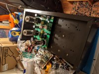
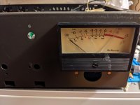
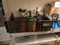
I found an old PA amp at a record store today for only 20 bucks. I decided to gut it to see if I can build the SSE inside of it. One interesting thing about the chassis is that it has a cut out for a vu meter. Is it possible to wire up a vu meter to use with the SSE? Any directions or insight on how to do this?
The main issue is that there's a center metal plate inside of it that separates the top from the bottom. I was thinking of mounting the board on top, with the choke and supplemental motor cap underneath. Then I'd leave the top off and maybe cut some perforated metal as a cover with holes for the tubes and to allow enough ventilation.
Does this look possible? Or should I scrap the idea and use a Hammond chassis I have instead?
Last edited:
I've decided to scrap the idea of using this salvaged chassis and just make a simple build using a Hammond enclosure. Apologies for the the long rambling posts. I'll start a new a thread when I get the transformers start building.
If you go the root of a Hammond enclosure, then consider the weight of the transformers, and whether you will have a motor run cap (which is bulky and best tucked away underneath). It is well worth sketching out your top plate before you order so that you are certain you can shoe horn it all together, with space between the power tubes and the transformers..
Also, is it possible that you should try and have the tubes on one side of the board and the other components on the other, so you can have the tubes on display?
The presentation is the hardest part!
Also, is it possible that you should try and have the tubes on one side of the board and the other components on the other, so you can have the tubes on display?
The presentation is the hardest part!
Thanks for the advice! I have a Hammond enclosure already that is fairly long but not very wide. I'll have to piece it all together when I get the transformers to figure out the best layout.
It's possible I'll still use the salvaged chassis, but I think it might be more work than it's worth. I'll try to decide once I get the transformers. I think the Hammond chassis would be easier.
Another question I have is if I just unsolder and resolder the four large capacitors to the bottom, could I still mount the board underneath the plate. That would work, right?
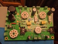
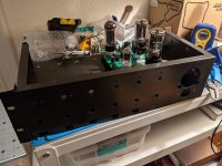
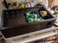
Got the amp up and running in a test set up a few days ago. Very stable, and sounds amazing! I set it up with the switches for UL and feedback and everything is working as it should. I can't really tell much of a difference with cascade feedback on or off but it's pretty apparent the differences between triode and UL.
When I have the time next weekend I'll start drilling the Hammond chassis and putting everything in it's final set up. It's been a.very interesting project to work on and I'm very happy with the sound.
When I have the time next weekend I'll start drilling the Hammond chassis and putting everything in it's final set up. It's been a.very interesting project to work on and I'm very happy with the sound.
- Home
- More Vendors...
- Tubelab
- Another noob needing help with his SSE Build