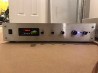
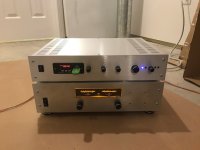
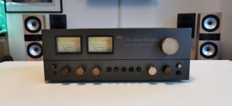
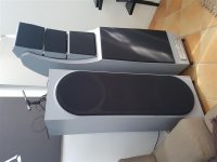
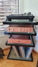
I recently acquired a Quad 306 power amp in excellent condition for free that was going to be thrown out, so of course, I had to take it! It powers on fine, and music plays through it, but the sound is quite muddy and distorted. Not massively, but enough to make it not fit for purpose as it is right now.
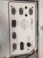
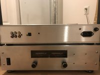
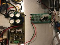
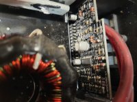
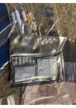
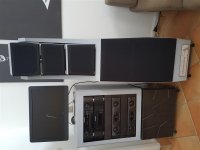
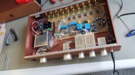
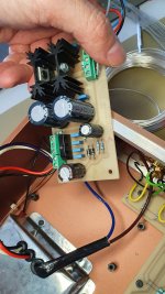
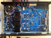
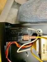
I opened it up to have a look, and I couldn't see any components that had obviously burnt out or anything. I did though notice that some modifications and some recapping had been done though. It looks like the 4 main (power supply?) capacitors have been replaced. The speaker inputs have been replaced, and looked like they were wired really badly to the PCB, so I desoldered the wires, and replaced them. This unfortunately did not help with the sound. I used 20AWG wire rated for 600V for this, is this wire fit for purpose?
Just a note, I'm not very experienced with electronics, I have some very rudimentary knowledge and basic soldering and multimeter skills, but I am keen and willing to learn.
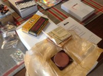
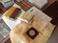
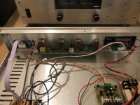
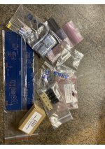
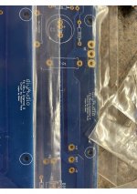
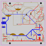
On the underside of the board, there are 8 100nf capacitors, film capacitors I think. I have done a bit of research, and I'm pretty certain these are to decrease the input sensitivity, as the Quad 306's sensitivity is 375mV out of the factory. I have attached some photos of this.
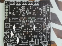
Could anyone help me work out by how much exactly this is decreasing the input sensitivity? And could this mod be causing the sound issues? Would desoldering them be ok? I will attach a photo of the top side of the PCB, in case anyone can spot any other changes that might have been made that I've missed. Some of the solder joints on the underside are touching each other, could this cause anything?
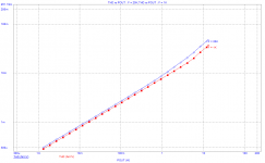
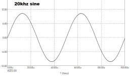
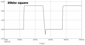
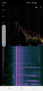
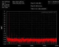
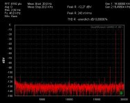
Also, what should I do in a situation like this where an amp has a sound issue? I have seen some advice elsewhere that involves sending a sine wave through the amplifier, but I don't think I have the equipment to do this.
Thanks in advance for any help!
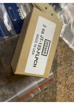
EDIT: I think I found some information on the mods that were done. It's a kit from here:
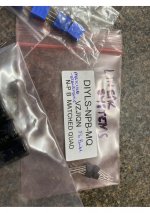
https://www.dadaelectronics.eu/uplo...als/Quad-306-Upgrade-Revision-Manual-V1.4.pdf . The resistors at R6 have been changed from 120ohm to 64ohms. I don't think R13 has been changed, so the input sensitivity hasn't been changed I don't think. R9 reads as 27 whereas it should be 33, and it does match the colour for a 27ohm, so this might be incorrectly installed. R11 reads as 120ohm but should be 47ohms, so it looks like this either shouldn't be here as well, or was put in for some reason. R21 reads as 0.01 or 0ohms whereas it should be 22ohm. It looks like the right colour resistor though, as R20 is a 22ohm as well and it's the same colours.
Oh, and I've just realised, if I am correct that the person who did this was following this companies mod, there are only 8 caps fitted on the underside, as opposed to 10 in their manual.
Here are the photos:
Quad 306 - Album on Imgur
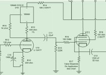
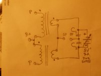
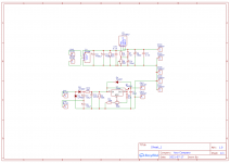
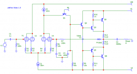
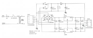
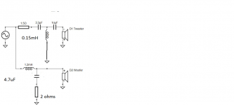
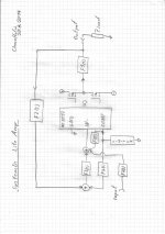
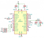
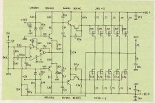
p.s. The schematic is here
Quad 306 Schematic and the manual is here
https://www.dadaelectronics.eu/uploads/downloads/02_Quad-Service-Manuals/Quad-306-Service-Manual.pdf


