Old sansui crossover help

Hi
I got this old pair of sansui esp 305 speakers and are seing if they need some replacing/repair and what not. I was just wondering if some of you guys understand the crossover better than me?

An externally hosted image should be here but it was not working when we last tested it.


The red wire is going to the woofer, yellow to mid, and blue to tweeter

I got it to be a crossover with 1.8kHz and 5kHz points from searching the web.

Hope some insight can be given
Imgur: The magic of the Internet

PS Audio GCPH problem, need help.

Hi. Lately it seems all my equipment is giving me greef… My PS Audio GCPH has developed a peculiar problem: if I don’t use it for a few days, left channel dies, but only on RCA output; on XLR output it works, but not as loud as it should be; right channel has nearly zero DC on output (0.1mv), and it does not change when I turn volume knob all the way up; left has about 1.3mv, and it goes higher and begins to cycle between about -6 to +6mv on full output. I wonder if it’s a simple re-cap job, or is the output chip kaput? I managed to find a reverse-engineered schematic online.
Thx

5c1 clone-ish

Hi Guys, I've built a 5C1 kind of amp but it seems low powered, with not much volume. Its is quiet ( no buzzes) and very clean until you put a pedal in front of it, then it comes alive but still not really enough volume.


The schematic shows the voltages I'm getting.


Any help and advice much appreciated.

Attachments

Does the EF88 exist?

Is there a forum member that actually saw an EF88 and/or has more information on this tube type?

As far as I know, the EF88 is only mentioned in "Comprehensive Valve Guide, Book 3, (Babani, 1960), in the seventh and later editions (so from 1961 going) of the "Electronic Tube Handbook" (Muiderkring) and in later editions of the AVO Valve Data Manual for Avo tube testers.

On Radiomuseum.org the EF88 has its own page, but I suspect this to be the result of the EF88 being mentioned in the Muiderkring handbook since the diagram for the EF88 comes from that handbook. The diagram does not show more information than de Babani guide does. Probably Muiderkring based their diagram on the data from the Babani guide.

EF 88, Tube EF88; Rohre EF 88 ID3876, Vacuum Pentode

At first sight it appears that there is some more info, like the pin-out diagram from a Telefunken handbook and a picture of the bottom side of the valve. But I could not find the EF88 in any Telefunken or Siemens handbook (but ofcourse I don't have acces to all their handbooks), so I suspect Radiomuseum.org used the pin-out diagram of the EF86 (or an other pentode with identical pin-out). And since the same picture of the bottom side of a Noval valve is also used on some pages of other Noval valves (mostly in cases where an actual picture of the valve type is not available) it is probably not a picture of the bottom side of an EF88.

The E88F surely does exist, but that is an EF80 intended to be used with an Noval to Loctal-8 adapter (the Philips/Mullard factory code on that E88F is identical to the factory code of the EF80). Since the pin-out and most of the other data of the EF80 are very different than that of the EF88, there seems to be no connection between the EF88 and the E88F (like for instance there is no connection between the EL81 and the E81L, the EF80 and the E80F, etc.).

E 88F, Tube E88F; Rohre E 88F ID51021, Vacuum Pentode

So to me the EF88 is a mistery. I never even saw a picture of one, let alone a datasheet with curves.

Earlier I posted this question on forums in The Netherlands and in the UK but without any result.

Transistor Amp Update

Hi, Last year with the help of this community I designed a power amplifier using ss8050, ss8055, bd139, bd140, tip41 and tip42 transistors.

The first build was a failure so I have been tweaking it based on comments from the last thread. I also raised the supply voltage so this is more like 25w/8ohm.

I have just been tweaking to get the THD as low as possible, but I am unsure if this would be a good sounding amplifier, any thoughts as to how it would sound? anything I should change before I prototype it?

also: why can't I find models or even datasheets for ss8055 transistor anymore? did I imagine it?

Attachments

ALK Xover for La Scalas...wow

I recently picked up a pair of La Scalas for $1250. One owner and in really good shape. Not being one to leave well enough alone I built the ALK universal xover. When i finished one I put it in so I could hear them side by side. What a difference... The boominess down low is gone. The tweeter and mid are louder isnt really the right word but more articulate. Crisper and faster sounding. I am really impressed. esp for the $200 the parts cost. Any Las Scalas owners on the fence about doing this shouldn't be. its sooo much better.

Onken for Audio Nirvana super 15 inch full range

Hello all,

First time posting, so I thought I’d take the opportunity to thank the community for all the info I’ve come across on this forum. I’m completely new to this and you guys have been a huge help up to now, but the more research I do, the more questions I have, so I’ve decided to jump down the rabbit hole and register as a member.

A friend of mine wants me to design a cabinet for a audio Nirvana Super 15 inch ferrite full range driver, and the enclosures that Audio Nirvana suggests are a one size fits all configuration of very basic bass reflex boxes, which makes me think there’s room for improvement.

I found out that the cabinet I’d sketched out was called an Onken type enclosure, and that those had been developed by “mad scientists” (not my words) who wrote down a rudimentary chart for proportions, but no actual formula.

I’ve found a calculator online : mh-audio.nl/Calculators/Onken.html which lets you put in the parameters of your driver and the size and number of vents and that gives you the total volume of the box and the length of the vents. Perfect!

I’d read you could simulate these in Winisd as well, so I figured it would give me additional information and check the maths. And this is where my issues start.

I’ve modeled the data I got from the online Onken calculator and found out that the box was tuned to 44 Hz.

As I mentioned above, I am new to this, and there is a lot of information to digest, so I have a bunch of questions, most of which will seem very basic. I am a fast learner though so bear with me please, and thank you in advance for your patience.

- The driver is rated for a free air frequency of 31,7 Hz, which is the default value Winisd gave me when I started the project. I am guessing I should aim to tune the box by tweaking the vents to be as close to that value as possible, correct? What is the consequence of the 44 Hz tuning that the online calculator suggested?

- The driver has a test bench frequency response from 31 Hz to 16000 Hz. Does that mean that I should set the minimal frequency on my model at 31 Hz and assume anything that happens on my model below 31 Hz will have no impact because there wouldn’t be a signal?

- Should I aim to have F3 as close to 31 Hz as I can?


I understand these parameters are determined through box volume and vent volume, and I can fiddle with those until I find the best curve. This will also determine wind velocity which should not exceed 18 m/s.

Then I started looking at cone excursion. And this is when the real issues started. The driver is rated for a 50 watt RMS which is what I set my signal to. And at that rate, the curve only drops beneath the drivers Xmax (1 mm) after 140 Hz or so. I understand you can filter out the signal up to a determined frequency on your source, but 140 Hz seems ridiculous. I can also get the curve to drop if I lower the input power, but I have to drop it to 3 W to get it below the 1 mm line, and that’s ridiculous as well. I’ve noticed the dimensions of the box have an influence on the cone excursion, and the smaller the box, the lower the curve, but if I want to drop below the 1 mm line, the box gets so small that I’m better off not bothering with a box at all.

I’d like to avoid filtering the signal as much as possible. There must be a way of designing the box so that it doesn’t blow the driver up.

So what am I missing? Up to cone excursion, I could (almost) get my head around the various parameters. But at this point, my model makes it look like the driver is unusable, which I’m sure is not the case, so what’s going on?

Many thanks for your insights, I’ve only just started and I am already very confused and frustrated!

Max

DIY Balanced Differential FirstWatt F6 Monoblocks

I recently delved into my first DIY FirstWatt amp build. I have some experience rebuilding vintage amps and thought this would be a fun change of pace.

I purchased two FirstWatt F6 kits - one is nearly complete, the other will be started after I finish the first amp and know I didn't screw anything up. I will build the first amp as it most commonly is - a single stereo amp but my ultimate plan has been to build two balanced differential monoblocks. I have always loved the looks of two monoblocks and, on occasion, wouldn't mind having a bit more power on tap to push the JBL L150's. I am reaching out to this community to critique my process and lend advice.

At a high level, I am planning to use two monoblock amplifiers, one for each channel. Where each monoblock uses the left and right channel outputs to handle the opposing side of the differential output signal.

In my research, one of the most complicated modifications would be producing the mirrored signal to make the amp differential. I picked up a Schiit Freya + preamp to solve this problem as it has balanced differential outputs. The other modified aspect of the design would be needing a floating ground.

Is there anything obvious (or not so obvious) that I am missing? Any tips on implementing a floating ground?

All my best,
Mike

Favorite Threads and Posts in "Full Range"

Favorite Threads and Posts in Full Range Forum

This permanent thread is a place for links to threads or posts in this particular forum that are useful and/or exemplify the best of DIY Audio.

This is so others- especially newer members can find them. Feel free to post with these links and a brief comment on what the thread discusses. Occasionally the moderators will consolidate them into fewer posts.

New compact workbench for amp repair

Everyone check out this setup! I built this workstation, which also has a table/desk underneath. I'm about 90% finished; just waiting for my Oscilloscope, and some electrical stuff like distribution blocks, RCAs, 1000w resistor packs. I was also thinking of putting some more volt meters and amp meters around for monitoring things during operation. Especially on the high amperage 12vDC side.

Ive been working on this bench for about 2 days. My goal was to create a compact space in which nothing but just the amplifier<s> I'm working with will sit on the countertop to hopefully and greatly reduce clutter. Everything else is hung up or sitting on a shelf above/below. I wired some of the outlets to switches and such so that equipment can be shut down when not in use etc. GFI outlet is constant which supplies 110vAC to the rest mainly controlled by switches and also ground fault protected.

Then the 12vDB components are protected at the main power supply using 60A fuse and a 200A main breaker. This can be upgraded later on as well. The setup can provide up to a few hundred amps burst, as well as fine tuning control during repair and such with a OVP/OCP 0-5A and soon a 0-20A supply.

The radio will be used as a test source and also for ambient audio. I wired the speakers to be switchable between the radio's built-in or the bench amplifier so I can play some audio while working, hit a switch and output from the amp to the speakers. Banana plugs, distribution blocks, RCAs will be in front, and wring is all on the back mostly hidden except for what to be used for hookup to the amps, and of course device probes. The Hako solder station is actually well positioned and long enough to solder anywhere on the bench as well.

The rubber mats are grooved and just floor matts from Lowes. I like the grooves because if a piece of and bits of wire happen to fall, they fall into the grooves and won't make contact with the work. Plus its easy on the amps and very comfortable.

Very excited. Hope to keep it

Attachments

  • IMG_0088.jpg
    IMG_0088.jpg
    430.5 KB · Views: 610

OLD PPI2300M Restoration problems

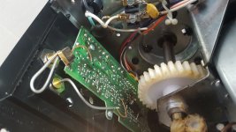
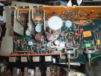
Hi im restoring a old blewup PPI 2300M
An externally hosted image should be here but it was not working when we last tested it.

and i got a problem with the power supply maybe it isnt the power supply

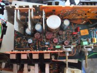
It had some 25N05N blown on 1 Channel
An externally hosted image should be here but it was not working when we last tested it.
i replaced all with the ones i tought the specs where closser IRF3205
An externally hosted image should be here but it was not working when we last tested it.
Datasheet
it still has the original Resistors 460 ohms and 2.2k ohms i checked them all and they are on tolerance

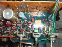
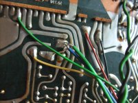
the other channel is ok with all the older semicounductors but the drivers because i was having DC voltage on the pads of the audio output on both channels (MPSU06 and MPSU56)
An externally hosted image should be here but it was not working when we last tested it.
Datasheet i replaced them by the MJE1530G Datasheet and MJE1531 Datasheet
An externally hosted image should be here but it was not working when we last tested it.

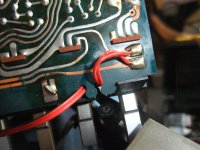
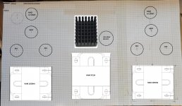
i had to put them backwards and twist the legs of pins 1 and 2 to match the old drivers
An externally hosted image should be here but it was not working when we last tested it.
EBC leg configuration
DC on Audio Output pads solved.
An externally hosted image should be here but it was not working when we last tested it.


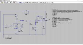
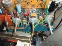
so i was having problems on the power supply waveform
the top was a little waved so i finished changing capacitors

Changed the ones with the mpsa056 on top of the ic sg3525a
An externally hosted image should be here but it was not working when we last tested it.
Datasheet
and got it fixed
An externally hosted image should be here but it was not working when we last tested it.
for short time wave was looking good but suddenly the waveform went to s*h*i*t*

this graph is taken at the Rectifiers
An externally hosted image should be here but it was not working when we last tested it.

it looks like its turning on then off and trying again
An externally hosted image should be here but it was not working when we last tested it.


this one is taken at the Gate
An externally hosted image should be here but it was not working when we last tested it.

and this one is at the drain
An externally hosted image should be here but it was not working when we last tested it.


so i took the irf3205 out and tested them with my chinese transistor tester
all of them look good

i removed the rectifiers and turned on the amp and this is the waveforms at the rectifier pads without the rectifiers
An externally hosted image should be here but it was not working when we last tested it.


so i tested the Rectifiers MUR810
An externally hosted image should be here but it was not working when we last tested it.
Datasheet
and they tested ok
An externally hosted image should be here but it was not working when we last tested it.


this is at the gates without rectifiers
An externally hosted image should be here but it was not working when we last tested it.

this one at the drains without rectifiers
An externally hosted image should be here but it was not working when we last tested it.


so i think the irf3205 are good
the ic sg3525an is good
Resistors are good

heres the waves of the ic sg3525an
the OSC
An externally hosted image should be here but it was not working when we last tested it.

PIN1
An externally hosted image should be here but it was not working when we last tested it.

PIN2
An externally hosted image should be here but it was not working when we last tested it.


Waveform Yotube Video Waveform Yotube Video

SG3525AN PIN VOLTAGES (FAILING) - (WORKING SIDE)
1 2.57 - 1 2.60
2 5.91 - 2 4.32
3 0.018 - 3 0.020
4 0.341 - 4 0.340
5 2.070 - 5 2.077
6 3.75 - 6 3.77
7 2.027 - 7 2.030
8 4.90 - 8 4.92
9 6.42 - 9 5.91
10 0.000 - 10 0.000
11 0.019 - 11 2.073
12 0.000 - 12 0.000
13 6.93 - 13 6.67
14 0.021 - 14 2.071
15 7.58 - 15 7.50
16 5.15 - 16 5.17

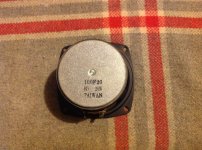
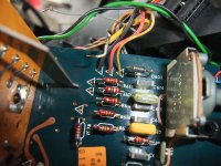
the audio output original transistors where the Motorola 2N6490 and 2N6487
An externally hosted image should be here but it was not working when we last tested it.
Datasheet
i got the Onsemi ones
An externally hosted image should be here but it was not working when we last tested it.

so no problem with that
replaced the bad and missing .22 ohm 2 watt M.O. Resistors

remember 1 channel still has the originals the one that is ok

when i remove all the new 2n6490 and 2n6487 power supply goes back to normal
i check the 2n6490 and 2n6487 with the transistor tester and they test ok

i always had te amp wired to a OCP OVP power supply setted at 12v and capped at 1 amp and i have 1 car light bulb in series on the positive line
An externally hosted image should be here but it was not working when we last tested it.


voltage between + and - wires after bulb 8.15v
all opamps has their +15-15v

it is posible to still damage a part with this setup?


help im stuck

Replacement PSU caps for Aleph 3

Hi, Mates!
1st time posting. Been out of the game for several years. I figure y'all are more up to date on stuff than I am so, hoping you can point me in a good direction here.

I have a Pass Aleph 3. I also have the schematic for it. It's been quite some time but I've had this thing apart several times to mess with wringing the most the most out of it. So, I know my way around this amp pretty well. Here's my dilemma. . . . .

It's definitely time to replace the PSU caps. I'd like to source new caps from Digikey or Mouser if possible. The stock caps are the Panasonic TSU 22000uf 25v @ 85°. It appears these caps are no longer made. What would be a good sounding replacement for these? I'd like to use a cap that has at least an equivalent ESR and also a little better voltage & temp rating. The caps can be SLIGHTLY larger - I can work around that.

Thanks for any recommendations you can offer!

BEST to You!
Bob

[need advice] 3-way (big) shelf speaker

Hey everyone.
I'm going to build a 3-way speaker based on
woofer: Tang Bang W5-1138SMF, 5.25" subwoofer driver

mid: Visaton B80
tweeter: Vifa XT25TG30-04

Both internet and simulation give 12 liter inner volume and ~35Hz port

The overall design is like these Xavian: 12mm oak, rounded sides, slot vented but with 3 drivers
Xavian_Ambra_enceintes_bibliotheque_bois_2.jpg


So my questions are:
1) Any advice on distance between twitter and mid? Cross will be set to ~3kHz, that gives ~11cm wavelength.

2) Is there any rule-of-thumb for twitter positioning on a front plate? Symmetric to sides but smaller distance to the top? All distances different?
Does twitter position makes a big difference if all corners are rounded?

2.5) Twitter in the middle? Any known drawbacks here?

3) Slot-port. Compared to the rounded port this type has more friction. What area overhead should I plan to compensate for that?

4) Other critique and advises are welcome.

TPA3110 board not bad, needs tweaks

I’m talking about the cheap amp board you can get on Ali (see attachment). It is very loud for something so small, but…

The R+ and R- output is mislabelled, should be other way round, you can hear it, but if you can’t, following the data sheet for TPA3110 shows the mistake.

The heat sink, if hasn’t come off already, will. But there is plenty of space on each side of the chip to make 2 holes and screw heat sink properly, after making 2 threads in it, and you probably want to do this because when it pumps power it gets noticeably hotter.

Which brings me to my last point, you would want to add a large capacitor across power input. That is if you wanna push the board.

Attachments

  • A5A09C7B-D525-470C-99D5-EE7A95CEBA2B.jpeg
    A5A09C7B-D525-470C-99D5-EE7A95CEBA2B.jpeg
    75.6 KB · Views: 156

Philips CDM12 INDUSTRIAL

Hi all,

I am new here and found a very good forum, tons of infos.

A freind of mine have a problem:
He owns a ALTIS alpha centauri Cd transport and lost the little plstic centering device for the Cd and the magnetical puck? thats hold the CD.
The drive is a CDM12 Industrial from Philps.I also have pictures but have to learn how i can upload that.
Searching a little on the net, i found that with the CDM12 industrial are 4 differents laser available and how ? many motors?
Where i can find this plastic device and which drive beside the PDM 12 have the same item?
Is there an partnumber or source to buy it?
Is there a replacement drive from daisy for it?
I think its a good idea to look beside this fixture also to search for the whole transport or least for the laser as the Altis is coming in the age.
Please help, so my friend get enjoyed and i get some wine for helpng him.
Please let me know,if more infos are needet.I have some picture and measurements from the CD table?

Thanks

Robert

Purifi modules + PSU + Buffers to sell : free shipment Europe.

Hi,

With a view to financing a new project:

I Sell my brand new PURIFI 1ET400A modules + SMPS1200A400 + Buffers with or without OP amps (in DIP8 sockets).
For Purifi measurements, check ASR. Great class D modules with amazing performances.

I provide PSU cable kits, from SMPS Hypex PSU to the Buffers.
NB : these are proprietary cables so I obviously include them

I ship to Europe for free.

Price : 840 euros.

Buffer spec :

- THD: 0,00026% @ Vin 2,5 V RMS
- GAIN: 14 dB
- BANDWIDTH: 2 Hz - 150 kHz
- SLEW RATE: 24 V/uS
- CMRR: > 100 dB @ 60 Hz
- DYNAMIC RANGE: 127 dB
- INPUT IMPEDANCE: 47 Kohm
- NOISE AND HUM: 6 uV
- SIZE : 62mm x63mm
- OP AMPS : OPA1665 (DIP 8)
- POWER SUPPLY: +-12V TO +-18V


FS: First Watt F5 PCB + Power Supply

[SOLD] FS: First Watt F5 PCB + Power Supply

Hi,

here I offer a set of pcbs to build a First Watt F5 in Pass style. ;-)
PCBs was layouted by Jeff Young.

PCB set price (amp left / amp right / power supply) = 35€
Shipping in germany (without islands) = 6€ (tracked / insured)
Shipping to outside from germany, please ask.

Thanks for looking ....Carsten

Attachments

  • IMG_5415D.jpg
    IMG_5415D.jpg
    739.8 KB · Views: 637

Trying to repair NOS Hypex DLCP.

Hi all,

So a year or so ago I acquired a DLCP on clearance, it appears the digital in/out chip is faulty however as I can access the bid through usb but not the usb audio device/spdif in so no audio out.

I've talked extensively with hypex but have got nowhere beyond the above understanding.

If anybody knows which chip is likely to deal with digital audio in, or how to identify which chip this would reduce e connected to, please let me know .

Thanks

Garage Door opener range extension on a Chamberlain 390MHz with 850CB remote

My Chamberlain garage door opener is vintage 1996, FCC ID: HBW1127 PN: 41A4252-7D. Worked great with decent range when it was new.

In the mean time I have a new garage door and a steel roof installed on my house. Ever since the range has reduced so much that it has become a real annoyance. 🙁

Now I have to be right in front of the garage door with my front bumper almost touching the door for the remote to work.

Well, I got annoyed and my wife complained enough so I finally looked at it. 😀

Over the years of been powered 24/7 eventually the charge capacitor dries up on the board and so this poor performing capacitor contributes to much reduced range.

I replaced the capacitor with a new and much lower ESR one, but that was not good enough to make a noticeable range improvement.

So I shifted gears higher, I installed a RF LNA SMA-67 with 14dB gain (up to 700MHz) and I replaced the stock wire antenna with a HB9CV antenna. This gives additional 4dBi antenna gain, it helps to make the receiver more sensitive & forward directional.

There is a very useful online antenna calculator I used.

For antenna construction I used 1/4" square brass tubing and 1/8" round brass tubing, a SMA connector, a 4/20pF trim capacitor, 2mm hex cap socket screws, 20mm OD x 50mm long PVC rod and solid 1.5mm wire.

I also used BNC panel female connector for the RF input and the Test Signal output.

Now I have easily some 200ft range through the closed garage door. That's good enough for me. I am certain if the antenna would be installed higher or outside range would be much much greater yet.

For those that are in the same boat getting annoyed by the range and that are interested in my tweak, below are some pictures of my construction.

Attachments

  • 390MHz Antenna_2.jpg
    390MHz Antenna_2.jpg
    372.6 KB · Views: 204
  • _20210821_124904.jpg
    _20210821_124904.jpg
    641.3 KB · Views: 214
  • _20210821_132830.jpg
    _20210821_132830.jpg
    634.6 KB · Views: 265
  • _20210821_132800.jpg
    _20210821_132800.jpg
    647.7 KB · Views: 554
  • _20210821_125810.jpg
    _20210821_125810.jpg
    658.1 KB · Views: 209
  • _20210821_125000.jpg
    _20210821_125000.jpg
    424 KB · Views: 170
  • _20181208_164752_.jpg
    _20181208_164752_.jpg
    944.4 KB · Views: 215
  • _20181208_173304_.jpg
    _20181208_173304_.jpg
    772.1 KB · Views: 210
  • _20181211_165138.jpg
    _20181211_165138.jpg
    947 KB · Views: 165
  • _20210821_125919.jpg
    _20210821_125919.jpg
    763.2 KB · Views: 218

KRK powered speaker setting bias

Here is another thread that I started on repairing these guys.
https://www.diyaudio.com/forums/solid-state/376026-2sc3281-2sa1302-sub-swap-tech-help.html

Quick summary: I blew an output.

These speakers were obviously worked on by another tech. The tech left notes about blown speakers and ground hums, all of which were solved by just replacing the electrolytic caps.

However, ALL 4 bias controls are turned all the way cold (2 speakers each being bi-amped = 4 controls)

So, I'm looking for some guidance on getting the bias set right, and have just a base understanding. i.e. Bias is for setting the crossover distortion(?)

Schematic attached.

Surely there must be more than my initial thought of just hooking a scope to the speaker output of these amps and adjusting the bias control until the crossover distortion is minimal? Watching the top and bottom half of the sinewave lining up?

Attachments

New to the forum. Planning 6L6GC SE Amp

Hello all!

First time posting and recently joined.

What a fantastic resource this forum is.

Id like to introduce myself. James 32 from Yorkshire, UK.

Always had a fascination with hifi audio. Mostly due to being surrounded by good gear of my fathers.

Last year I completed a rebuild of a Armstrong based ECL86 stereo push-pull amplifier which I was very happy with after it was left in bits in the garage on my dads to do list. Anyway it is now in service and has left me wanting to build my own amplifier.


I have settled on 6L6GC SE amp and would like some input / verification my design is sound. I know simulation is not always perfect and might want some changes along the way. I have attached a LTspice simulation.

I think I have got the biasing correct. But my simulation is currently producing circa +/-30v to the 6L6GC control grid. The simulation suggests no clipping etc but seems excessive. Any thoughts?

The amp is likely to be powered with a 5U4GB rectifier, and looking at some Edcor power transformers and Edcor 5K to 8 Ohm 10w output transformers.

Look forward to hearing your thoughts and comments.

Many thanks

James

Attachments

FS Peerless 830669 + 27TDFC/TV (Manzanita kit)

  • Peerless SLS 830669 - 12" Woofer
  • Seas 27TDFC tweeter
  • Sledgehammer 12mH 15 gauge inductor
  • 0.8 mH aircore inductor
  • 12uF film capacitor
These were just gather dust.. so need a new home. Includes dust, I haven't cleaned anything.


Boxed up & ready to arrive on your doorstep. from switzerland post should be 34CHF in europe. 44CHF to USA.


less than 10hours use, i can't take responsibility for damage in transit.


Ferguson PVD transformer

Hi DIY Audio buffs,

I have a Ferguson PVD 111 Transformer for a Williamson 6V6GT AB class PP Ultralinear build I am building.

It has a voltage doubling capacity with the following input/outputs:
230,240,250 VAC primary
124,114,104 or 310,285,260 outputs on HT secs
and two 6.3 (CT) outputs on secs.

With 15 wires to decifer, I was hoping someone could explain the function of the PVD system or might have the color codes used.
The primaries and Filament outputs are east but the HT secondaries are more challenging.
I need to work out the internal workings to allow testing of the trannie without risk of damage. Any help much appreciated.
Thanks
Mark from Kalgoorlie.

Something between Burson Audio Funk and Audioengine N22

Hi, I'm new here, and noob 🙂() but I would like to know a little bit about amps, so I'm looking for something between the Burson Audio Funk and the Audioengine N22.

So that do I'm looking for exactly:

- Power Class A/B between 22 - 45 watts
- Potentiometer Alps or better (as in Burson Funk): I need a well "synchronized/matching" volume as in Funk, the one that N22 has is pretty crappy specially at low volumes.
- low noise (close to 0 distortion at 100% volume): Funk has pretty good low noise at 100% volume in either headphones/amp.
- metal enclosure for better head dissipation
- Small form factor: both n22 and funk are very small and have the power supply separated from the amp.
- No pops, Funk has pops when turning off the amp.
- 2 RCA inputs (Funk has 1 rca / n22 has 1 rca, 1 3.5 trs)
- headphone amp (optional but very welcome) balanced if possible with at least 5volts for planars/dynamics
- high gain / low gain headphone selector (optional)

I think that's all, I'm not looking for anything fancy like remote control or LCD displays or digital switches, just the basic but well built.

Linn LK1 eprom

Hi chaps i have a Linn LK1 preamp that is lighting up like a Christmas tree and bugger all music coming out
I have changed majority of the caps on the control boardstill the same
I was going to change a couple of the ICs next and got them on order from ebay
There is a mk3 labled eprom that would be the next thing to change
I was wondering if anyone had the eprom programing data for this chip if I needed a new one
I'm not into electronics but really enjoying this challenge
Any advice would be appreciated
Thanks
Gary

A WMTMW or WWMTM design for my room issues?

Hello, right thank you for your reading. Here's my question about a tower configuration I'm planning to build for using in my living room in a certain position.
In the past, I've already built other floorstanding speakers, always two way with one 8'' woofer placed right under tweeter, for an overall height of about 1 meter: my struggle was born because I couldn't ever obtained any good bass response from them in my typical listening position. To listen some bass I've had to go in other rooms or better on the upper floor! Only using a sub against the angle floor/rear wall (away from edge with other walls) I could obtain good basses, but I don't want to use a sub.
plan.png

So I'm planning to build some new woofer design and I liked Jim Holtz's Statements II or Anthology (in the version with the same drivers of Statements II, which somebody already built and called 'Statements II remix'), the first WMTMW and the second WWMTM.
What I'd want to know from you is what of those may give better bass response in my room: the first because has two woofer near the floor or the second because has two woofers far from each other and distributed in the vertical space?
elevation.png

I must say that positioning them at 60 cm from the rear wall is a bit bothersome because I've children and I'll move speakers forth and back when listening, but really I love basses and I couldn't find good design able to do that staying against the rear wall. In case please could you suggest me any? I'd like to experiment some high efficiency design, as horn or TL, important is the bass response!

Thank you very much.

Raspberry Power Supply

Hello all,

I'm considering a upgrade from the standard raspberry pi 4 switching-mode power supply (Buy a Raspberry Pi 15.3W USB-C Power Supply – Raspberry Pi) to a low noise power supply in order to take the most advantage of the HF SDR equipament connected to it.
I have a switching-mode power supply from my previous HF trasnceiver: 15V, 30AMP PS. Thus I thought of using a linear regulator connected to this power supply, setting the output voltage to 5.1V. I'm currently looking at LM138/LM338 regulators.


What are your advice?
Better to get a dedicated PS from the 230V mains for the raspberry pi to minimize the noise?


Thank you in advance

Shenzhen PCB Assembly - You Don't Want to Miss

Hey, are there any hardware engineers on DIYAudio seeking PCB assembly?

Here is a reliable one-stop PCB assembler in Shenzhen - PCBONLINE. Our clients are around the globe. You will want to work with PCBONLINE when you know us:

  • PCBONLINE is an advanced turnkey PCB assembly manufacturing company founded in 1999.
  • Our PCB assembly capabilities include rigid-flex, HDI, stacked micro-vias, fine-pitch BGA, and QFN assembly.
  • Our PCB assembly follows IPC-A- 610 Class 3 and is compliant with ISO9001:2015, REACH, UL, RoHS, and IATF 16949.
  • Our solution experts provide one-on-one engineering support and always seek to reduce clients' costs with the latest technologies and manufacturing optimization.

Contact PCBONLINE by email at info@pcbonline.com.
Know more about SMT and PTH PCB assembly at PCBONLINE from our webpage: [Official] PCBONLINE: SMT Assembly and PTH PCB Assembly of the Highest Quality

Protect circuit strange behaviour

All,

I am working on a Denon AVR-1513 exhibiting some strange behaviour. The receiver works normally, except for these two.

1. All three protect relays (FR, FL, C, SR/SL) energize immediately when the power switch is pressed. There is no delay. The light flashes green during (as if there was a delay) and then becomes solid.

2. The receiver does not "lock" onto HDMI sources (PCM icon and HDMI icon are flashing intermittently). Analog sources work just fine. After a few seconds of trying to lock on the receiver goes into protect mode

Findings.

1. Voltages at the speaker outputs are all normal. Voltages at the bias adjust test points are 2.5mv +- .5 mv.

2. Sound quality is good from non-HDMI digital sources and analog sources.

3. HDMI output (i.e. Menu screens etc.) look good.

4. The receive does not report any errors in service mode.

Note:

1. Lots of floating grounds in this receiver. MCU has a floating ground, as does the analog pre-/power amp sections. When checking voltages you have to reference the correct ground or your readings will be erroneous.

ikonw8

Amp reliability question.

Hello, hope everyone is well.

Knowing there are people here with great knowledge of amplifiers and can give unbiased opinion, I thought I’d ask this here rather than a typical audio forum where people will argue about brands.

Was thinking of possibly selling old amps to buy a newer higher power unit and the Taramps caught my eye. I have a vague recollection of them being similar to other Brazilian amps, and it seemed other Brazilian brands were unreliable years ago, however, I do not really recall the Taramps or perhaps my recollection is just wrong.

Any thoughts on these? Perhaps the SMART model / line? Or even other current models.

I have not done amp repair in years and have zero experience with them. I haven't even really messed with audio gear in quite some years now.

Thank you for reading and any input, I greatly appreciate it.

Slim GR dMar-Ken7 Ov9l build

Thinking of another Alpair -7MS gold 5" build. The last time I put 1/2" felt on each side of the brace. Was this really necessary? Or could I have done without it? What difference will there be in sound quality without the felt? See attached. The first I used the Alpair 7P which after breaking then in sound fantastic.

Also what does anyone think about the advice given by Mapleshade recording regarding speaker placement & design? Mapleshade recommends the use of brass screws to mount the speaker drivers to the baffle. Something about a reduction in transfer of vibration. He also recommends not to fully tighten the frame to the baffle as well. Take note about the internal wiring as well.

Free Upgrade Advice

Some interesting thoughts & concepts

baffle tape & blade.jpg

Thanks

Noval tube/valve pins

Not sure if this is best in here, or the tube forum.
I'm putting together some nine pin noval base tube adaptors, but seem unable to source suitable base pins. They are approximately .9mm in diameter but I can't seem to find a suitable source. Either individual pins over 10mm long or stiff wire of the appropriate diameter would do.
Has anyone come across this or have any ideas.

Foster E120 please identify

The photo below is from a pair of planar tweeters I have labeled Foster E120. Performance similar to the E110 but goes lower. Pretty similar performance to the Mundorf very very expensive tweeters.

Can anybody please help me find more information about this unit. I believe Infinity used some from this series in their top of the line speakers.

Thanks.
Ben

Attachments

  • E120 front.JPG
    E120 front.JPG
    187.1 KB · Views: 119
  • E120 back.JPG
    E120 back.JPG
    217.7 KB · Views: 130

Combining Wires

Forgive the simple (I hope) question.
I am trying to use Coleman's Raw DC boards but the maximum wire size the terminal connectors at the boards will accept is 18g AWG. The transformer he recommended has two 16g AWG. I have tried the euroblock form of connectors but the larger size is for a minimum of 14g and the smaller one is to small for the two 16g transformer wires. Even if that would work, I am hesitant to use a short piece of 18g to "adapt down from the two 16g wires.

Any ideas?

-V Grid Bias Supply - Positive or Negative?

-V Grid bias supplies can and have been done with diodes oriented either way. ie. with positive rail tied to the signal circuit ground as in a stacked supply, or negative rail out with ground to ground. Voltagewise they both add to the same but I wonder if there are undesirable effects from the positive supply rail connected to the signal circuit's ground when operating. Not good enough at LTspice to check it out that way myself - Can anyone offer comment?

Thanks

Need help identifying 4" driver

Many years ago I was given a pair of 4" mid-bass drivers by Joe Talia of Talia Sound and Vision. One of them now has a punctured surround and I'm trying to find a replacement. I can't locate it by the model number, maybe someone knows it.

Seems to be the sort of driver that would be used in a large TV or maybe car audio?

Attachments

  • 100F20 Front.jpg
    100F20 Front.jpg
    155.4 KB · Views: 114
  • 100F20 Rear.jpg
    100F20 Rear.jpg
    167.9 KB · Views: 111

Grundig Satellit 3400 - Images wanted of a completely Dismantled Device

There are numerous photos of this model on the web, - go to
Grundig Satellit 3400 und der BFO / SSB Knopf – DL2YMR s Blog
Grundig Satelit 3400 Professionell lässt sich einschalten aber es kommt kein Mucks, Hifi-Klassiker - HIFI-FORUM
FM problem on Satellit 3400 - UK Vintage Radio Repair and Restoration Discussion Forum
GRUNDIG Satellit 3400 professional KW MW SW UHF UKW Empfanger

but not of the power supply + amplifier unit alone when it is in dismantled condition. This images I have upload here.

To remove this unit from this device, numerous steps must be observed that are not described in detail in the service manual - go to
GRUNDIG SATELLIT-3400 SM Service Manual download, schematics, eeprom, repair info for electronics experts

Therefore it was very difficult for me, among other things due numerous cables that have to be unsoldered and because of the very tight space available.
With the help of a second device of the same model, I succeeded.

After removing some contact issues at the variable resistors and assemble of the PS/amp unit there was at both devices still to observe a more or less effective contact resistance in the signal path (variation of output level similar like on a defektive volume control pot - both on FM and AM-ranges).

After long search I note, reason therefore ​​​​​​​is a crack of conductor track (at both devices of this model) between 15m and 19a of StV301 (push-button switch assembly.

To avoid dismantling the entire device (to get to the soldering side of the main board), a cable connection was simply soldered between the soldering connections 15m and 19a of StV301.

Are there anywhere pictures on the web from a completely dismantled device of this model and the associated steps of this process ?

Best thanks for posting an URL.

Attachments

  • DSCF7601.jpg
    DSCF7601.jpg
    1,021.2 KB · Views: 364
  • DSCF7599.jpg
    DSCF7599.jpg
    1 MB · Views: 363
  • DSCF7596.jpg
    DSCF7596.jpg
    1,020.2 KB · Views: 303
  • DSCF7597.jpg
    DSCF7597.jpg
    1 MB · Views: 305
  • DSCF7594.jpg
    DSCF7594.jpg
    1 MB · Views: 312
  • DSCF7590.jpg
    DSCF7590.jpg
    1 MB · Views: 337
  • DSCF7589.jpg
    DSCF7589.jpg
    1 MB · Views: 381
  • DSCF7587.jpg
    DSCF7587.jpg
    997.9 KB · Views: 246
  • DSCF7584.jpg
    DSCF7584.jpg
    1,020.5 KB · Views: 261
  • DSCF7581.jpg
    DSCF7581.jpg
    999.2 KB · Views: 299

Mains filter Islatrol IC+207

New/unused and very clearly industrial quality. I bought it but the size does not fit my casing and it is in this case very over rated with regards to power. Excellent specifications. Sturdy connectors for ring type crimp connectors. Since it is completely epoxy encapsulated no oxidation or things like that.

7.5A at 240V makes for 1.8 kW which should be sufficient in the Class A amplifier territory. I thought about filtering the whole group but decided on an audio mains filter for my relatively low power devices.

Specifications:

https://docs.rs-online.com/2aed/0900766b8140ec12.pdf

Yes that is 60 dB in normal and common mode (please see the frequencies) 🙂 I would like to have 75 Euro for it. Shipping only within Europe. Advice is to use an IEC inlet with built in fuse to connect to this filter.

Attachments

  • IMG_2585.jpg
    IMG_2585.jpg
    952.8 KB · Views: 155
  • Islatrol-IC+130-Series.jpg
    Islatrol-IC+130-Series.jpg
    76.5 KB · Views: 148

ML-2 Regulator Board

One of my Mark Levinson 2 ML-2s is kicking off at turn-on. Substitution found a malfunction in the regulator board. Which ever amp I put the good board in works and the other with the suspect board does not. I had hoped it would be the thyristor as it seemed to be the highest power and hottest device on the board and therefore the most likely to fail. Took in out and tested it at 30 volts and .6 amps. Touching the anode to gate turns it on and it stays on till the current drops to 9 ma. It will turn back on with current as low as 10 ma when re-touching the anode to gate. Seems like it is good and that is about as far as my knowledge will take me. I am hoping for either some good tech guidance from the forum or a recommendation of a fair and competent repair service that is well familiar with these boards I just had my Quads rebuilt last year and have now lost an amp. Hope you can help.

Hypex DLCP shutting down frequently

Hi folks


I have been running a DLCP / DLCP SMPS happily for a couple of years now driving my 3 way Wavecor / Accuton / AMT through Class A amps.

Recently it started shutting down intermittently, but would happily power back on .. for a while. I suspected an SMPS issue, and indeed the DLCP datasheet states that the unit will shut down if the +ve rail drops below 15v.
I contacted Hypex support, who had been helpful in repairing the SMPS failures (electrolytics) in my 4 NC400s, but they offer no replacement or repair of the SMPS DLCP.

The DLCP setup is in a Ghent Audio case, and runs fairly warm. So as it seemed a temp related issue, I removed the top case half for a good look around. Nothing too obvious, so tried running with the top off, so to speak.
Voila, no shutdown ! Tested for hours, happily listening to the music ..
So what runs hot ? Well, the voltage regulators, for a start. So I found some heat sink packs for £10 shipped, which needed some mods (saws involved) to get them in the space. Even after my work, everything still powered up and ran.
So on with the lid again .. all works OK, so leave it to sit on my favourite radio station with the amps off for a while. Boo, after an hour or two, down she goes. So it's drill time .. sorrry Mr Ghent, there's now a big slot under the row of 6 regs, and 3 decent sized holes in front of the SMPS to waft cooling air towards the slots in the back panel. Tested OK for a while, but despite all my efforts, it still shuts down, haven't done much to help.
What possibilities ??
Replacing SMPS electolytic caps (going on previous experience) - beyond my capabilities. Anyone know capable repairers of SMPS in UK / Europe ?
I know other Hypex SMPS are supposed to support the DLCP via J16 input to the DLCP, and I can see the Aux outputs of many are appropriate around +/- 20v, but where does that leave the digital circuits which require +8v ? If its OK why wouldn't Hypex support suggest buying an SMPS 400A100, for example?


Does any one here have a solution ?


cheers, Maurice

Power transformer design paper

I'd promised to make this available a long time ago. This is a copy of a hand out I got when I was doing my post graduate course in advanced electronic design at IISc in Bangalore some 25 years ago ! With design software available nowadays this might seem unnecessary. Bit it IS interesting and those who do not have software , they might find it illuminating .

I completed typing out the material from the frayed cyclostyled papers just now and so it might have typo's or some small errors . I did go through it quickly twice but it might have some small errors.

There are a few graphs that go along with it but they look bad as the papers are faded and have splotches on them . I need to clean them up ( digitally ) before putting them up.

The question is , should I really spend time doing this ? Would enough people be really be interested in this document today ?
I find it interesting enough to go through through them again.
Could be useful to those who want to wind their own special transformers or modify some they have .

Let me know if I should put up the cleaned up charts also .

To SY and other moderators . The document is just a set of cyclostyled papers. It doesn't mention an author's name ( or editor ) and there is no copyright mentioned either. It does give a course number ( ES6-217 - IISc Bangalore ) . It was compiled by Swiss industry experts .
So I guess it's OK to put this up on this forum ?
Cheers,
Ashok.

Attachments

Finished My 45 Parafeed Headphone Amp

Finished my 45 parafeed headphone amp today, nothing innovative, but wanted to share it, I think it turned out well. Been at this hobby since January, so this is my second from scratch design-to-build amplifier, the other being a 6A5G-based SET.

It is a MOSFET cascdoe CCS loaded 6J5 input, MOSFET cascode CCS loaded 45 output parafeed design for high-end headphones. Mains transformer is a custom job by Sowter to my spec, OPT are Sowter 8983. Filament regulators are Rod Coleman's, coupling and parafeed caps are Rike Audio S-Cap 2 (paper, poly, aluminum, oil). Power supply is a single rail CLCRC.

DSCF5611.jpg

11224562.jpg

Here is the schematic, although it is not comprehensive. Parafeed capacitance was determined experimentally by taking FR sweeps of various capacitances (courtesy of cheap Solen caps), along with subjective listening impressions. Ultimately decided on 6.6uF made up of two 3.3uF in parallel.

45 Parafeed Schematic.png

45 Parafeed PS.png

Bias points:

6J5 B+: 380V
6J5 plate to cathode: 200V
6J5 cathode: 6.2V
6J5 plate current: 8.5mA

45 B+: 398V
45 plate to cathode: 206V
45 cathode: 35.5V
45 plate current: 35mA

Here are some shots of the interior. Bottom plate is perforated aluminum sheet for ventilation.

DSCF5602.jpg

DSCF5603.jpg

DSCF5605.jpg

DSCF5609.jpg

Here is a FFT of the left channel at 350mV into 300ohms.

11230661.png

And the frequency response.

11230659.png

Thanks for checking it out! Going to experiment with changing the 6J5 unbypassed cathode resistor to some stacked HLMP-6000 LEDs later today.
  • Like
Reactions: nicoch58

Change capacitors 25 year old + vintage speaker

Hi all, just wondering if i should change capacitors on my 25year old plus vintage speakers i have aquired? I will post images so people can get an idea of what im dealing with - Just to clarify speakers sound great but maybe a little rolled off on the tweeter but not sure as that might be how the speaker sounded originally. Thanks

Attachments

Audioquest nighthawk headphones

Headband is quite worn
Silver original cable is missing, other original cable is included + diy cable.
Earpads are recently changed.
Price 150.- + shipping in EU
Photos
IMG_20210518_122153.jpg - Google Drive
IMG_20210518_122139.jpg - Google Drive
IMG_20210518_122320.jpg - Google Drive
IMG_20210518_122305.jpg - Google Drive
IMG_20210518_122330.jpg - Google Drive

Toroidal placement help/ question

Question. I was hoping to install a 200va toroidal transformer in chassis that measures 5” wide. The toroidal measures I believe 4.90 so it fits but with a millimeter or two in between the walls if that. Is this a ok or safe to have it so close to the walls of the chassis or should consider a wider chassis? Any thoughts or opinions would be greatly appreciated. The picture is just for reference and have know intentions of fitting it in that. Just happens to be 5” wide. Thanks

Attachments

  • 765D8774-93DE-49F1-93BE-22240B5BD3D7.jpg
    765D8774-93DE-49F1-93BE-22240B5BD3D7.jpg
    976.3 KB · Views: 197

Newbie looking for advice on stereo amp layout

Hello everyone!

I have decided to build a valve audio amplifier as part of my (late) middle life crisis management. It's been more then 40 years since I have done anything with valves, it's time to go back to the future 🙂

I'm looking to build a class AB1 stereo amp, based on 6L6 (6P3S-E) valves, been working on the component layout, and it would be great if you can comment on it. No need to be gentle, I can take punishment 😀

Thank you very much!

Jose

Attachments

  • stereo_pp_amp_layout.jpg
    stereo_pp_amp_layout.jpg
    818.5 KB · Views: 282

Cheap CD Experiments

Hello everyone,

I've recently been in contact with a Chinese supplier of horn and other goodies.

I've managed to convince them to send me free samples (see pictures 1 and 2).
They do have a wide variety of horns (at least 150 different models).

Most of it seems to be unbranded JBL Pro stuff.
Dimensions are formatted this way:
w*h*l all units are mm

Big horn:
370 x 190 x 165

Front:
An externally hosted image should be here but it was not working when we last tested it.


Front angle:
An externally hosted image should be here but it was not working when we last tested it.


Top:
An externally hosted image should be here but it was not working when we last tested it.


Back
An externally hosted image should be here but it was not working when we last tested it.


Small horn:
200 x 95 x 80

Front:
An externally hosted image should be here but it was not working when we last tested it.


Front angle:
An externally hosted image should be here but it was not working when we last tested it.


Top:
An externally hosted image should be here but it was not working when we last tested it.


Back:
An externally hosted image should be here but it was not working when we last tested it.


Now the question is, what cheap CD would you advise using with horns like these? It'll run active with a Minidsp 2x4 HD.
I've been looking at a couple of different drivers myself, including:

Celestion CDX1-1748.
Build-in 1" 3/8 threading. Very smooth response. Minimum crossover at 1600hz.
An externally hosted image should be here but it was not working when we last tested it.


.Kartesian Cmp35_vPA
Smooth response. "new driver"?. I haven't seen it mentioned much.
An externally hosted image should be here but it was not working when we last tested it.


RCF ND350
falling response towards the treble area, 2. order HPF would probably smooth it enough?
An externally hosted image should be here but it was not working when we last tested it.


What else could you recommend me to try out?
My budget is 100-150€. I will document my findings using a Umik-1 in the future.

Preamp output Creek 4040s2

Hello!


Just wondering if there was a way to use the preamp of the 4040s2 for an external power amp.
I'm building a power amp at the moment but the diy preamp world seems to have abandoned classic analogue tone controls which I really can't live without. So it would be nice if the Creek could be modified to steal the signal before it enters the power amp section.
I've researched the same thing for an NAD 3020e and it turns out that it would be possible but not advisable for some reason.


Or if there is a preamp/input selector (diy) solution with a decent analogue tone and volume control, I'd be happy to hear about it.


Thanks!

L-pad for compression driver

I'm designing an 2 way speaker with a compression driver and a midwoofer for someone and i have an issue with the big sensivity difference. Most people will arrange this with an dsp and seperate amps but for the client that is not an option at all (it needs to be foolproof for a noob and easy to set up). He will use it for various small events, mostly as background music or for presentations in a non-profit organisation but the space he uses is big.

How do you do the Lpad to take 10dB difference. The woofer is a 300W woofer and the compression driver a 60w and it will be used to it's limit sometimes. CR is a 4th order passive at 1600hz. normal resistor L-pads (with 10w or 20w resistors) won't take that load i think. Can you use a pot meter for that (internal in the cabinet set at the right point). Or do you use high power resistors like those in a metal housing like this one? https://www.mouser.be/ProductDetail...GAEpiMZZMtlubZbdhIBIOzZS54oCXX/hbM1Vkal%2BcQ= (just an example of format, not that value).

And yes, i know it's not optimal and it will create a lot of heat. But the client insist on a passive crossover and want to take the disadvantages of it. Normally i would use a dsp for this (altoug i also like passive crossovers, but even after long insisting on using a dsp he refuses.

0.8µV Ultralow noise DAC power supply regulator 3.3/5/7V 1.5A*x2

2 LT3042 based modules both new/unused and one of them has heavier rated coils. As you can see the original coils are with the set.

I fitted the superb German quality Phoenix connectors that are made from real copper and not iron.

What about 70 for both shipping with Germany/Netherlands included? Send me a PM if you want these. No shipping to other countries, sorry.

Attachments

  • IMG_2113.jpg
    IMG_2113.jpg
    810.7 KB · Views: 557

(Aus) Biema pro amps for (sub)woofer use

Has anyone had experience with Biema pro amps for (sub)woofer use?
http://www.biema.com/html/product/amplifiers/q.htm

Am looking for a moderate cost amplification to power the woofer section (2 x 12") in the NaO.

Someone at Madisound forums suggested the QSC RMX 850 as good value at USD$300, but here in Australia it costs USD$900.
:-(

Am considering the Q250 or Q400 (for Aussies, the Altronics product code is A4164 or A4170)
Projects by fanatics, for fanatics
Get answers and advice for everyone wanting to learn the art of audio.
Join the Community
507,638
Members
7,881,956
Messages

Filter

Forum Statistics

Threads
405,935
Messages
7,881,956
Members
507,638
Latest member
Sheikh Jobayed ahmed