Linn KAIRN as a pure Phono RIAA Preamp like LINTO with MM (for better Sonic Results)

Because Linn's LINTO in used condition is more expensive than a KAIRN this idea rises up and was realized several times. Additional sound quality is better than from LINTO and an additional benefit is the possibility of using also the MM input. A disadvantage is the fact, that MM/MC cannot be use at the same time, because therefore a switch selector would be necessary.
Follow steps are to perform:

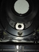
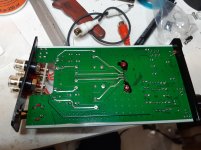
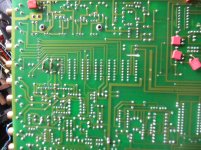
1) Prepare output sockets "MATRIX" for line out of this phono preamp section to avoid any influence by C-MOS switching effects:
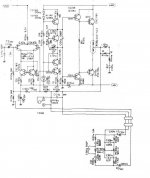
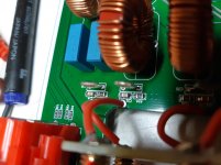
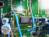
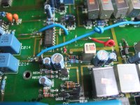
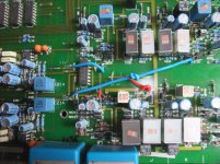
- Cutting conductor track from node R072/272 as well as C018/218 and C019/219 (L/R) to PIN3/PIN14 of U307 (DG309CJ, C-MOS source selector) - go to image No 1, 2 and 3.
- Use this existing output sockets to which these conductor tracks are connected as line-out of this phono preamp

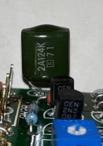
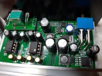
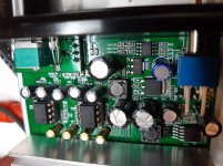
2) Bypass C-MOS switch for switching between MM/MC by cutting the conductor track to IC U301 (DG309J):
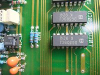
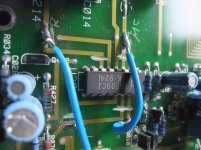
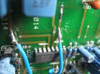
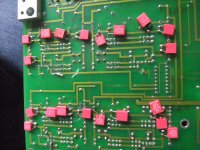
- cutting the conductor from C014/214 (output MC input stage) to PIN 3/6 (L / R), U301 - go to image No. 4,5 and 7
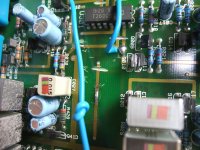
- cutting the conductor path from node C027/227 and R043/243-R070/270 (output MM level) to PIN 11/14, U301 - go to image No. 4,5,6,7 and 8
- cutting the conductor from the base Q10/210 (input, phono output stage) to PIN 10/15, U301- go also to image No. 4,5,6,7 and 8
- soldering a cable from the input of the phono output stage
- either to the output of the MC input stage - was done at this example, go to image No. 4-9 and 10 (solder side view), 2x blue cable
- or to the output of the MM input stage (short red cable ends provided as marking at the output of the MM input stage, go to image No. 8 and 9)

3) disconnect front board from the main board by removing the plug

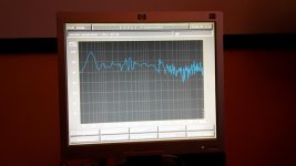
Now sound quality is much more better (mainly due the absence of RF from the operating/MCU board and because no longer C-MOS switches in the signal pad).

Attachments

  • Linn KAIRN MATRIX=Phono-Out.jpg
    Linn KAIRN MATRIX=Phono-Out.jpg
    1,023.6 KB · Views: 447
  • Linn KAIRN R072,272,C018,218,C019,219 - PIN3,14 U307-I.jpg
    Linn KAIRN R072,272,C018,218,C019,219 - PIN3,14 U307-I.jpg
    1,014.5 KB · Views: 474
  • Linn KAIRN R072,272,C018,218,C019,219 - PIN3,14 U307-II.jpg
    Linn KAIRN R072,272,C018,218,C019,219 - PIN3,14 U307-II.jpg
    1,003.9 KB · Views: 401
  • Linn KAIRN C014,214 trace U301 PIN 3,6-I.jpg
    Linn KAIRN C014,214 trace U301 PIN 3,6-I.jpg
    1,015 KB · Views: 431
  • Linn KAIRN C014,214 trace U301, PIN 3,6-II.jpg
    Linn KAIRN C014,214 trace U301, PIN 3,6-II.jpg
    994.2 KB · Views: 356
  • Linn KAIRN C027,227 trace U301, PIN 11,14.jpg
    Linn KAIRN C027,227 trace U301, PIN 11,14.jpg
    1,006.7 KB · Views: 228
  • Linn KAIRN C027,227 trace U301, PIN 11,14-II.jpg
    Linn KAIRN C027,227 trace U301, PIN 11,14-II.jpg
    1,003.3 KB · Views: 228
  • Linn KAIRN MM out red cable-I.jpg
    Linn KAIRN MM out red cable-I.jpg
    1,002.4 KB · Views: 234
  • Linn KAIRN MM out red cable-II.jpg
    Linn KAIRN MM out red cable-II.jpg
    1 MB · Views: 248
  • Linn KAIRN U301, PIN10,15, trace Q10,210-II.jpg
    Linn KAIRN U301, PIN10,15, trace Q10,210-II.jpg
    1 MB · Views: 383

RW-10 - RW-10D / RW-12 - RW-12D REPAIR BLOG

Hello All

I have been repairing Klipsch subwoofer amps for about 15 years as a hobby. I have decided to start blogging my repairs and eventually do videos of each one. This thread is intended to be a blog and a resource for information. I will try to answer repair questions as best I can. Comments and tips are also welcome, If you do not have the experience or the tools, PLEASE do not attempt any of these repairs. You will only end up damaging the board and it will end up costing more for a tech to repair the damage. If you do not have a high quality vacuum desoldering station (Hakko or Weller) and a current limited mains supply, you should not be working on these amps. These subwoofers do not have any user serviceable parts inside. If you open up the sub or attempt any repair you see in this thread, you are doing so at your own risk!!!

Using digipots, AD5263 in particular

Just curious if anyone used AD5263 to replace normal pots on prefabricated tone boards? I tried AD5206 and MCP4341, used in feedback loop for OP amp they work fine, but not all of those ready made boards offer gain control via feedback resistance, so they just don't work as drop in replacement.

The reason I am trying AD5263 now is because it is quad potentiometer and the only one that can operate at +15V from AD range. It has digital and analog supply separated. So I'm wondering if someone used it with success and has any design tips?

another NAD 304 whit the red light on...

Hi, today I turn on my NAD 304...the power light is in red, and the soft cliping in yellow. Nothing about green colour.😡
I have reading post, and i cannot see were are the r333 and r334 resistors.😕
Beside, I have the schematics from internet, but it is poor quality scanned.
I´m not have idea about to repair, but my brother is very good with videoconsoles, and he knows electricity...but nothing about english.😀
I would aprecciate help to me...NAD sound very well for me, and I dont have enough money to buy a new amplifier.🙁
I will expecting your help with opened arms....thank you in advance.😉

Replacement motor for Well Tempered turntable

Hi all,

The motor has ceased working on the Well Tempered Versalex turntable I own - it played one side of a record fine, then after I flipped sides the motor just stopped working all together. I'm about to test the power supply just to make sure that's not the issue. But in case it's the motor itself, has anyone experience switching one out? I imagine it's the same motor used with the Simplex and Amadeus.

Cheers,
Ben

Sony xm-7547

this amp has an offset fault. I have all the bias pots turned counterclockwise. When I disable the offset protection and check the test points 3 out of the 4 are ove r the .04-.05mv without adjusting the pots at all. The rages are from .06 to .09mv. I have a working 2 channel version of this amp I can reference from i just dont know where to start.

SMPS question , sry guys I dont get it

Hi Guys, Hi Perry - long time no see ;-)

I have a 2 ch. amp that has a semi "dual" smps. that means 2 transoformers , driven by 4 banks of mosfets. if I connect all 4 mosfet banks without the transformers all looks fine on the oszi, the "dual" banks are driven by two driver transistors.

The "outside" of both lines is in parallel, so if only one transformer is connected it supplies all channels with outside voltage, dre outputs work fine as well as the filters, etc.

If i connect the 2nd transformer input coils the amp still works, if i connect one of the 2nd trans output coils to the rectifiers it still works, if I connect the 2nd output coil of the 2nd trans the amp goes into protect. Currently I rewinded the 2nd trans output coils, waiting for the result..... any Ideas besides a short in the 2nd trans output coils ? the rectifiers are ok and the amps , filters, etc are all ok. any other idea in case the new coils would cause the same issue?

Lots and lots of tubes, advice needed

So, I got my hands on some tubes.
Somewhere around 1000 of them and a few hundred of them are in sealed boxes, so they are not the problem.

The problem is the other 300-400 tubes in opened boxes and the other 5-6 shoe boxes of mixed tubes.

There are some power tubes (el34, el84, 6v6 mostly)
And some in the ECC-family.

But most are for me unknown.

If I go by prices on eBay I would be financially independent so I take those prices with a grain of salt...

Anyway, do you guys think it would be worth it to invest in a u-tracer, or another sub $250 tester to test the tubes and then sell them off?
I plan on keeping some for myself but most of them I want to sell of to finance other stuff.

I would appreciate any and all advice

See attached photos for some of them.

Attachments

  • IMG_20200510_085143_resized_20200513_081019805.jpg
    IMG_20200510_085143_resized_20200513_081019805.jpg
    333.7 KB · Views: 544
  • IMG_20200510_100521_resized_20200513_081018263.jpg
    IMG_20200510_100521_resized_20200513_081018263.jpg
    212 KB · Views: 554
  • IMG_20200511_065041_resized_20200513_081019354.jpg
    IMG_20200511_065041_resized_20200513_081019354.jpg
    250.5 KB · Views: 531
  • IMG_20200511_153902_resized_20200513_081018702.jpg
    IMG_20200511_153902_resized_20200513_081018702.jpg
    267.4 KB · Views: 522
  • IMG_20200511_154623_resized_20200513_081018046.jpg
    IMG_20200511_154623_resized_20200513_081018046.jpg
    347.4 KB · Views: 523
  • IMG_20200511_154631_resized_20200513_081019560.jpg
    IMG_20200511_154631_resized_20200513_081019560.jpg
    337.7 KB · Views: 259
  • IMG_20200511_154645_resized_20200513_081019149.jpg
    IMG_20200511_154645_resized_20200513_081019149.jpg
    271 KB · Views: 232
  • IMG_20200511_163826_resized_20200513_081018468.jpg
    IMG_20200511_163826_resized_20200513_081018468.jpg
    245.9 KB · Views: 199
  • IMG_20200512_161035_resized_20200513_081018848.jpg
    IMG_20200512_161035_resized_20200513_081018848.jpg
    296.5 KB · Views: 268
  • IMG_20200512_185350_resized_20200513_081019022.jpg
    IMG_20200512_185350_resized_20200513_081019022.jpg
    249.5 KB · Views: 286

PANASONIC-QUASAR SERVICE INFO REQUEST

This may be a long shot but I figured I'd ask around...
I'm coming up dead-end for service info/schematics or PDF's for a Panasonic RX-5600 (not the LS) boombox. (circa 1979/1980)

Apparently it's also known under the Quasar brand - GX-3661


I have the "LS" (european) manual, but the tuner board is way different, among other sections, and I need to troubleshoot the reason why the tuning signal strength meter doesn't work on FM, but fine on AM.


If anyone can dig up the service manual for me, I'd appreciate it, thanks.

Shout out to REL Acoustics

Just a shout out to REL Acoustics for there support in repairing my amplified subwoofer.

I contacted them to see if I could get a schematic, service manual, or the bias procedure for the amp in my REL T-3 as it blew an output transistor.

They didn't have a manual or schematic to share, but they did send me the bias procedure. But where I felt they went beyond my expectations is they provided me a list of things to check that may have caused the problem and were very specific, calling out specific components on the board.

They also told me what they replace as a matter if course when doing repairs.

On a side note, their repair service runs $340 and includes shipping back to the owner. But considering the cost to ship the subwoofer to them (probably $50), it shows why so many things get thrown away these days. $400 would go a long ways towards a new and better sub.
But $16 for a set to output transistors (or maybe $50 if I did the recap they recommended) gives this sub a new life and keeps it out of a landfill.

Repair your stuff and save the planet!

Reading output transistors in sets

I have an amp that has 4 output transistors. 2 NPN in parallel and two PNP on parallel (Sanyo D1047 and B817C).

I have one bad PNP.

So I know I have to replace both PNPs, but do I need to also replace the pair of NPNs?

If so, do I need to match the NPNs to the PNPs and how the heck do I do that? Note that these are listed as complementary pairs by Sanyo.

Since each pair is wired in parallel, do I need to match the transistors within each pair? I would think that since they are in parallel, they essentially work as one unit and it would be more important to match across the pairs.

Finally, they are used Sanyo products available, but for new I can get either OnSemi or unbranded. I'm thinking if I can get used Sanyos form a good amp that may be better as they will more likely match the original specs and any required matching would have been likely done by the amp manufacturer.

Help with Definitive Technology Mythos STS Amplifier

Hi everyone,

I'm looking for some help on a Class D amplifier which is making some funny sounds.

The amp is a Definitive Technology Mythos STS, although from what I can tell it's basically the same as the Definitive Technology 7002, 7004, 7006 etc.
The main Class D amp module is a DS-3000 which I believe is used in many Class D amps and subs.

The amp itself works. However there is a low noise coming from the sub.
A continuous low volume humming (at low freq) and then randomly a loud scratching noise almost like the voice coil us rubbing on something.

The low hum is not really audible normally, but the random scratching is. In fact people in the house think it was a storm or something till I pointed out it was the speaker.
This happens with no input.

The circuit is basically
Input > Low pass > EQ > Limiter > Limiter high pass > Limiter low pass > Class D Amp.

I removed the cap between Limiter low pass and Class D amp, and the noise is gone. This indicates to me that the Class D amp is fine and the noise is come from before that.

I have checked the voltages and they are all fine. There is a +- 15V rail and it measures +15.05V and -14.95V. Does the 0.1V difference matter?

Does anyone have any suggestions as to what may be causing this random noise? Or which part of the circuit may be responsible?

Thanks

Technics SP-10 Doesn't Spin

Hello everyone,

I recently purchased a SP-10 MKII in "as is" condition so no complaints about the seller. It powers on and the strobe lights but that is it, no platter movement at all. I have minimal electronic experience. I have looked at the troubleshooting section here, Library Downloads - Vinyl Engine

I have taken some voltage readings but my low level skills don't allow me to interpret them, many of which are way off. Below are the readings I got:


E15 26.01V 28.18V

TR118 E 6.06V .408V
C 21.17V 28.13V
B 6.69V .121V

TR115 B .771V
C .162V

TR116 B .103V
C 6.07V

TR117 B .113V
C 6.07V .46V

D101 26V 0V

D106 6.7V 6.01V

D107 6.01V 0V


P3 20.52V

Any help would be greatly appreciated!

Thank you,
Jim

Quasi-parametric equaliser

For the beginning, I will explain the title as I see it:
A parametric equalizer has three knobs for each field of frequency; one for the adjustment of the frequency, one for the level and one for the bandwidth covered by the given central frequency.
Having three bands, such an equalizer becomes difficult to use and if you are not decided of what to use it for, you will waste more time turning the buttons than listening to music.
That’s why such equalizers are almost exclusively used in the field of professional music production, where technicians and sound engineers can approximate well enough what frequencies should be set, at least as a starting point.
Personally, after I tried inclusively a 30 bands graphic equalizer, I reached the conclusion that for shaping the sound as I please, there aren’t necessary so many bands, because it takes too long to get the desired result.
I managed to obtain the sound I like - which means a slight deviation from the sound of a record that could have been better mixed – with a 4 buttons equalizer: bass, mid, mid central frequency control from 1000 to 8000 Hz and high. Which is exactly what a channel of Behringer Xenyx X1622 mixer that I owe is offering. In that case, the controls are a bit extreme, so I would search for something less aggressive, suitable to be used in the Hi-Fi system; therefore not +/-15 dB as in case of professional mixers, but something around 6 dB or a little more.
Has anyone didactic materials on this purpose? I will put here what I found, but I have to admit that I don’t master the mathematics so well, in order to calculate exactly such an equalizer. I proposed the discussion here an I would use operational amplifiers, let’s say LM833 or NE5532, perhaps 4558, as Behringer usually does, but it would be even more interesting if someone had the courage to do something like this on tubes. I propose ECC83 as active element in this case. But any constructive practical idea would be welcome. I am not in the expensive opamps field...but any suggestion is welcome.
I would like to have these specs:
Bass: frequency of control at 80 Hz, +/-6 dB
Parametric mids: +/-6 dB, control of frequency from 1 to 8 Khz
I don’t mind if the control of bandwidth appears here too, at least as a trimmer, but I’d rather like a preset, well calculated version; maybe a switch with 2 or 3 positions. Also, at +/- 6 dB, I only want to easily match the sound/I only want to adjust the sound a little. I already have the console for the extreme controls, but I will never modify so much the music I listen in my Hi-Fi setup.
It would be awesome if I’d have the scheme of the Behringer mixer, but it is untraceable.
There’s what I have for now. I will be back as I will be able to get the useful material:
Simple, Easy Parametric and Graphic EQ's, Plus Peaks and Notches
Also I received the schematic of a proffesional MIDAS parametric equaliser, a bit too sophisticated, but for sure good sounding...I’m not sure if I’m allowed to post it here, PM me if interested.
I am sure that once built, such a device will be to the liking of many music listeners.
...I am not speaking to the audiophiles, but to the lovers of musical auditions. My idea is to keep things as simple as possible, without affecting the quality of sound.
P.S. If there's already such thread, please redirect me there or move my post entirely...but it doesn't seem to be such thing, or at least some project easy to be taylored to my desired specs...

Denon Experts? AVR X3400H all sound just died

I have a x3400H - it had been working perfectly and all of a sudden, in middle of a stream. ALL the audio went out - video remained intact, but in mid-sentence all audio just went out completely
I tried other inputs, incl tuner and still nothing; also a firmware update (to see if it would reset some aspects without losing all my settings)
Went to the speaker test tone and got nothing on the first one (left front) - nor would it change the level value, or be able to select the other speakers; it would go 'back' but when tried again, same thing, stalls on the first speaker without allowing any changes to the value or ability to select other speakers.
Ultimately I tried a factory reset:
During the (Re)Initialization it got through to the speaker setup section; when it started to test left speaker, the setup froze - I did not hear anything regardless, but it would not progress, NOR back from that point in the setup (no response from the on-screen GUI);
Did another re-initialization, got to same point and again re-froze
I re-initialized once more and this time skipped that (speaker setup) part of the setup - proceeded to set everything else up
During the Internet setup it tries different preset audio links for sound confirmation (really to test the internet connection as opposed to speakers) - I got nothing audible on any of the 4 links tested
Then went back to manual speaker setup - again got the same issue as previous to reset - i.e. it stalls on the first speaker, no audio tone, cannot adjust that speaker level, nor change to another speaker, but will go 'back'

It seems like a hardware problem - not sure where to go from here?
Appreciate any help/suggestions

  • Locked
B&O 50ASX2SE in casing

A fully functional 50ASX2SE power amplifier in a casing BUT the upper cover is missing. Still directly usable. Good quality RCA connectors and speaker binding posts too. It has a mains power switch and green 3 mm LED power indicator (soft glowing). I glued the heatsinks to the various hotter parts just for longevity. I like the sound quality but it is equal to another amplifier I have so it is superfluous.

Make me an offer via PM. I prefer to ship it within the EU.

Attachments

  • IMG_1003.jpg
    IMG_1003.jpg
    972 KB · Views: 267

Need help understanding transformer impedance ratios and impedance matching

I am a bit confused about impedance ratios and actual impedances of the primary and secondary of a transformer when it comes to matching a source to a load.

An impedance ratio of 10:1 is required - for matching a 10k load to a 100k source.

Now there are two transformers both having an impedance ratio of 10:1 but one of them is spec'd as having a 600 ohm secondary and the other with a 15000 ohm secondary. My understanding is that if I put a 10k load on either of these transformer's secondary, the primary will simply reflect a 10x (100k) load to the source.

Then what does 600ohm and 15000ohm mean ? What impedance is this ?

Jensen JHP-51, 100 ohm VC?

I came across a 1940s Jensen JHP-51, hoping to mate it with a JHP-52 I already had. These look almost the same, same cone, same spider, and both came with 500 ohm impedance matching transformers and coaxially mounted tweeters.

But then came the surprise: I measure the JHP-51 VC, has an 88 ohm DC resistance (guessing around 100 ohm impedance). And indeed, the transformer has a 2.25 turns ratio, resulting in the expected 500 ohm external connection. Out of curiosity I connected it up to a receiver with 8 ohm output and listened to it at low volume for a short time, and it works.

The JHP-52, the later model, has a more typical 8 ohm VC, mated with a 8 turns-ratio transformer, also resulting in the expected 500 ohm external connection.

The 500 ohm reflected impedance is not surprising, there are many examples (sounds like there were even some speakers with 500 ohm voice coils). But the 100 ohm voice coil was a surprise, and I don't see any other reference to such thing anywhere. Was it entirely a one-off, completely non-standard thing? Since I don't want to use the 500 ohm impedance, I will likely replace the coil with an 8 ohm one, to match the JHP-52.

Harman Kardon 330B Receiver Voltage Rectifier Specs

Hi, I have an old Harman Kardon 330B receiver with a bad power supply. Can anyone assist me in finding a suitable replacement? The service manual I found lists the part as T1 part number 10129496 (export) or 10129497 (domestic). There's no reference to the specifications. I have no clue to the specs other than 120v in.

Thanks in advance.

QiBo

Attachments

  • IMG_0459.jpg
    IMG_0459.jpg
    376.8 KB · Views: 58

Phase margin and gain on LTSpice.

NOTE: This is NOT a help request but a suggestion to try using a ready made example in LTSpice. The example schematic is audioamp.asc.

Note 2: For fun and curiosity I added a current mirror and two emitter resistors of value 22R and the distortion figure went down to 0.005%. Originally it was about 0.3%.

It is needless to state that current mirrors and current sources are a blessing!

About a Luxman amp

Hello

As you can see, this Luxman amp do not use a preamp, the power amp do have a high gain and the tone control are in the feedback with a switch to bypass that tone control

Do adding a buffer circuit at the input would be a good idea and how about using the Pass B1 as a buffer for this amp ?

Is there any improvements that can be done in that amp circuit ?

Thank you

Bye

Gaetan

Attachments

  • luxman2.JPG
    luxman2.JPG
    216.7 KB · Views: 255

Sony XA5ES

Selling my beloved CD player. This was the final CD transport to me.

I have had quite many transports before this one, including other Sony's like newer top of the line, Esoteric, Wadia, etc. I have had this for about 2 years. This was honestly the first and the only time I could really hear the difference between transports - in a positive way. Of course, this is just my subjective opinion.. but just saying that there is night and day difference between the late model transports that are mostly based on a cheap multi norm computer drives. This one is actually sturdy and well build for audio purposes.

I can not say anything about the DAC in this player except that it works, since I have only used it as a transport.

I'm considering the best Sony transport (and player) to be XA7ES. This is the same device, except that in XA7ES there is more copper insulation in the chassis and the DAc is a bit different.

About the price, just make me an offer and this might be yours. Just check Hifishark or ebay to get a ballpark where these go but this will be cheaper since I don't need this anymore 😉 I have finally moved to streaming.

Everything works as expected but the only drawbacks are the missing remote control and there is some wear on the top plate of the chassis (note, this is aluminum, not plastic.

This weighs a lot but can be shipped anywhere, just ask for shipping price.

Attachments

  • IMG_20210813_170521.jpg
    IMG_20210813_170521.jpg
    695 KB · Views: 381
  • IMG_20210813_170527.jpg
    IMG_20210813_170527.jpg
    676 KB · Views: 382
  • IMG_20210813_170537.jpg
    IMG_20210813_170537.jpg
    544.9 KB · Views: 386
  • IMG_20210813_170621.jpg
    IMG_20210813_170621.jpg
    707.7 KB · Views: 367
  • IMG_20210813_170638.jpg
    IMG_20210813_170638.jpg
    515.7 KB · Views: 365
  • IMG_20210813_170650.jpg
    IMG_20210813_170650.jpg
    487.9 KB · Views: 161

Cambridge Audio A1 V3 - One Channel Missing

Good Morning Everyone.

This is my first post, so hope i have it in the correct forum.

I have the above titles amp which has lost a channel.

I have traced a sine wave input as per the circuit diagram above. but i lose voltage to -inA.

I can trace the 10mV from the output of the Op-amp to where it enters the LM4766, but i Lose it at one point.

i have checked continuity and i have replaced CC33 to no avail.

i have another chip on order just in case a signal is being brought down within the chip, but other than that i can't find anything wrong.

The volume and balance control are working ok, and ive removed caps and tested them with an ESR meter and all ok.

Any help would be appreciated.
Circuit diagram came from a person on this site.

Thank You


https://lms-digital.co.uk/sites/choco/images/1234.jpg


https://lms-digital.co.uk/sites/choco/images/13363601773_1192eab047_o.gif

Cheap low voltage (100V HT) 32R headphone amp.

This is low voltage headphone amp designed to drive 32R cans. The OPT is a multi-comp 120-0-120 0-12 0-12 1.6VA toroidal transformer to be cheap. The biggest problem is the primary capacitance with using mains transformers, which forms a dominant pole and limits the drive at high frequencies. Its for an FM tuner project so the HF is quite well controlled.

Comments please before I prototype would be appreciated (good or bad).

Attachments

  • Screenshot (62).png
    Screenshot (62).png
    107.5 KB · Views: 241

More rewarding speaker directivity pattern for in-room stereo listening

Prologue

Since 2011 I was beating my head against the simple problem: my two-way loudspeaker prototype came out great sounding but measured almost poorly. I hope you can trust me there is not much of exaggeration here - it sounded great despite being just one speaker (I did not have room big enough to assemble two of them). My other-half was so impressed that demanded that I build another one and place them in our bedroom immediately after cosmetic uplift (of course). It took longer than expected, but I'm not worried.

Out of all audible subjective qualities of the speaker prototype I'd like to mention great micro-dynamics, very detailed sound on low to moderate level, nice overall bass balance with generous midbass, large presentation with speaker almost disappearing (yes, listening from just mono source!), nice clarity even at low listening levels, pleasant near-field listening despite the solid size of loudspeaker and significant distance between LF/HF drivers. Also great was 'around the corner' listening experience as sound was coherent and pleasant also when listening from nearby room. The most important was the fact hat speaker brought less brain fatigue than I used to have while ever listening to other speakers. Also there was something special about spatial aspects of the overall sound that seemed to be much better then usual. Speaker was assembled and tested in the sonically untreated (except various clutter in shelves working as nice dispersers) and small (2x3x2.5m) listening room. See attached drawing to get the idea of the enclosure design.

So when speaker was finished and initially tweaked we sat there in small, cold workshop me and my wife listening through lots of great music that we both love for a couple of hours like it was the first time we hear them. I named speakers RAD TQWT as RAD also stands for 'joy'. Assuming this sounds too romantic for serious thread, more pragmatic description will follow 🙂

Any flaws? Yes. a) limited macrodynamics b) sound being slightly too forward (at this point there was no back tweeter connected and whizzer cones weren't removed yet). When i really wanted to "crank it up" midbass speakers reached cone breakup levels met with SET amp power limits. That's something surely can be addressed with adding more bands and making it 3- or 4-way with separate bass amp, but the goal was to build a best possible two-way. Did we ever wanted to listen much louder? No, it really was big and loud enough at non-distorted levels with just a few watts of applied power.

Attachments

FS: Shure SME Model 3009

I am selling my SHURE SME 3009 tonearm. It has been recently rewired with Cardas copper tonearm wire, the tonearm has been checked and cleaned and it is functioning perfectly. If I am not mistaken this should be the series 2 non-improved version, that is the most sought after.
Item is located in Budapest (Hungary), but I am happy to ship it anywhere. It will be well-packed.

Asking price: EUR 640 inclusive of shipping.

ols2Zy6.jpg

SgrXYQD.jpg

uha0oRJ.jpg

nalmwoV.jpg

qbYxv4L.jpg

7kFdnE6.jpg

Reccommendations for a preamp build based on my gain and impedance needssetups

Reccommendations for a preamp build based on my gain and impedance needs

Hi all. I recently bought a partially working Quad 306 power amplifier, had to replace a few components, and whilst I was at it I changed the input sensitivity to 1V. I've tried it with the pre-out of a Schiit Vali 2 headphone amp with my main speaker, and it sounds pretty good and probably better than my main integrated amplifier which is a NAD C316BEE.

So, I'm in need of a preamp. I have built a Bottlehead Crack headphone amp kit before, so I was thinking of possibly ordering and making their Moreplay preamp. However, I have seen many other preamp builds on here and elsewhere that have caught my eye. Such as: DIY ECC802S (12AU7 / ECC82) Vacuum Tube SRPP Preamplifier and Low-mu preamp

I would be using it with my Trichord Dino MkII with Dino+ PS. Am I correct in thinking that because of the switchable loading capacitance, resistance and gain this makes this phono stage more flexible to fit into a setup?

My knowledge of electrical circuits and things such as the input/output impedance of amplifiers is VERY basic, but I'd like to learn. Because of this, I would love to get some advice or to be pointed in the right direction with this build.

My requirements for the preamp is 2 or 3 unbalanced selectable inputs and no phono stage needed. Possibly remote-controlled volume, but only if it makes sense in the build and isn't too complicated. I would like to make a tube preamp, and probably one that adds some 'tube sound', as I've got a feeling it might work well with the Quad 306.

With regards to gain and input/output impedance requirements, this is where I need some help, as I don't really know where to start.

I have tried to do some research myself on what my requirements are, and I hope this doesn't come across as a 'recommend me the best kit/build' type of thread with no self-research done, but I'm just a bit overwhelmed with all the information.

Thank you in advance for any help!

Chris

19" Rackmount case, ideal for amp project. UK

FS, 19" fronted aluminium case, dimensions are 425mm wide (48cm/19" front) by 350mm deep by 83mm high approx. Main body is drop pressed/cast 2mm thick, 2mm thick approx top cover. Good sturdy construction, weighs 2kg approx, see pics.

I'm after £30 for it which is what I paid. Courier is £5.50 Hermes 3 day, UK only. Might consider EU postage but this is a bit of a nightmare after leaving the EU.

Drop me a PM if interested. Andy.

Attachments

  • DSC00466.JPG
    DSC00466.JPG
    161.7 KB · Views: 208
  • DSC00467.JPG
    DSC00467.JPG
    162.2 KB · Views: 202
  • DSC00468.JPG
    DSC00468.JPG
    161.1 KB · Views: 215
  • DSC00469.JPG
    DSC00469.JPG
    162.1 KB · Views: 187
  • DSC00471.JPG
    DSC00471.JPG
    161.5 KB · Views: 207

Manger

Hi Eric

The Manger project is looking as follows.

The MSW and a Dynaudio 20W75 are currently mounted in an ugly particle-board (I think this is the correct expression - in German it is "Spanplatte") box. It is somehow similar to a Manger Zerobox 109 (not the uglyness for heaven's sake, but the construction).

It is currently in use for casual listening just to break in the drivers. In about three weeks I will make measurements, to be able to design the crossover.
There is currently only a first-order crossover in use, and I am feeling ashamed for using electrolytics for this purpose, but IMO this doesn't play any role when it comes to break in of drivers.
Though the woofer is in this case able to mess up the midrange (1st order lowpass) and the electrolytics are by no means sonically good, the box sounds quite astonishing. Imaging is already quite O.K. and the sound is more detailed as with my other box currently in use (two-way with Dynaudio D260 and 17W-LQ).

As soon as the drivers are measured I will build the prototype electronics. The crossover will be of the subtractive type (+ some equalization), and output power between 50 and 100 watts approx per driver. I will do this on Veroboard only since ist is just for trying any tweaking around.
This will be built into the prototype box and I will listen to it for some time (until the final one is finished). I will keep the electronics for further use (experiments with other crossover/driver combinations also non FR ones).

The final box will not use the Dynaudio driver but one from Audio Technology (currently in the make). This driver is a little larger than the Dynaudio one (it will have about three times it's Vd) and response of the closed box will be equalised flat to around 40 Hz. Maybe I will even make the rolloff selectable, I don't know yet.
So even with this box (that will definitely be larger than the current one) the prototype electronics will again be needed for tweaking before the final electronics is designed and built.
So the whole thing is something like an approximation process.

I don't know how long this hole thing will take, since I don't have much spare time for things like that.

Regards

Charles

Questions to Acapella Celestron Delta 4 with Plasma Corona Ion Tweeter

This loudspeaker system from German's manufacturer Acapella is a 4 way version. The speaker utilizes 3 spherical wave horns.
The bass horn is presumably fitted with the Dynaudio 30W54, the midrange horn with the Dynaudio D54.
For the highs, the Corona Ion tweeter is used.
The horns are supported by a sepearate bass enclosure below 230 Hz. The bass enclosure is an infinite baffle system with four (roughly) 30cm/12" woofers each. The bass enclosure is 220cm/7'4" tall!
Pictures are here:
Hornlautsprechersystem ACAPELLA TRIOLON EXCALIBUR MK II (first image)
and
Dayton Wright Audio Links (sroll down)
The upper three ways must actually be the same than used by the Triolon - go to
Review Hornspeaker Acapella Triolon
The currently user want an additional IB subwoofer system similar to those from the first picture by post # about this thread:
Ultimate Solution for an User with already present "InWall" Subwoofer:ESL or dynamicL - diyAudio
and pictures from post 15 about
New Approach for an Outline from a DIY Subwoofer - Precision Devices PD2150 inside - Page 2 - diyAudio
First step before realizing a subwoofer project was to investigate the frequency responses from the lower three ways
to find out any anomalies. I create near field measurements and such at the listening place.
First question is, who know about meaningful measurements in test reviews of this loudspeaker of of the Triolon ?
Now the description to the three images of frequency response (I use DAAS3NT - go to the attached PDF in post #3):

First picture shows the nearfield measurements of frequency response from the lower three ways. Left curvature (blue) is those from the 220cm/7'4" tall bass enclosure (closed box, not vented box). the middle curvature (white) shows the large spherical wave horn with Dynaudio's 30W54 - and the right one (also white) those of the midrange spherical wave horn with Dynaudio's midrange dome D54. All three curvatures are from the left channel. Right channel provide the same results in the near field.

Second picture shows the response at the listening place from left channel (please ignore the yellow curvature) and the right channel at listening place shows the third picture. The different from left and right channel - particularly below 1 KHz comes from different conditions concerning the arrangement by installation: Right channel stands near by the right side wall in opposite to the left channel - the left side wall is far away.

The most the most striking detail is the wide band overlap of the first and second curvature from first picture so as the peak of the second curvature (30W54) which is in absence at listening place only at the right channel near the wall. What was here the goal from the developers ???

Attachments

  • 20150328_180237.jpg
    20150328_180237.jpg
    969 KB · Views: 233
  • 20150328_181747.jpg
    20150328_181747.jpg
    387.2 KB · Views: 207
  • 20150328_183147.jpg
    20150328_183147.jpg
    374.3 KB · Views: 203

Looking for an American pen pal to learn English

Hello, I am currently learning English on the site ISpeakSpokeSpoken, Youtube channel in particular, to be able to progress I need a pen pal, preferably American man who wants to learn French, who would have if possible the same passion as me, the old electronic audio devices and in particular the tape recorders, I am a man and I am 66 years old, my level of English is between A2 and B1, I can express myself but with the help of a translator.
We could correspond in chats with the help of the site tandem.net.
If someone can help me in my search, I would be very grateful.
Sincerely,

Christian

Here are three YouTube links showing my work:
Le Magnétophone Acémaphone PA52B d'Yves SGUBBI - YouTube
Rénovation totale de l'Amplificateur Hitone H300 de 1968 - YouTube
My complete renovation of my first wire recorder Webster Chicago Model 80- 1 - YouTube

Looking for datasheets of 1980's/90's Marcon and IC electrolytic caps

Datasheets of 1980's/90's Marcon and IC electrolytic caps


I am looking for the datasheets of the original electrolytic capacitors used in a Rowland Consummate preamp. Due to the age of the preamp (nearly 30 years) I want to replace the electrolytics. I would like to look up the specs of the originals before deciding what to replace them with.

There are 3 different types:

4 x 1000uF/25V marked IC LBAM M85{degree}C 2K07A
12 x 6800uF/35V marked Marcon AWF-M20 +85{degree}C 3B08A
6 x 100uF/63V marked IC RMRM B105{degree}C 22

I have tried asking in the power supply forum but had no luck. Sorry for the cross posting but I thought people here might not read the other forum.

PS I know it is not a Pass preamp, but I use it to power my Pass Aleph 3 so the posting is marginally appropriate 😀

Help please with rare tube cd player

Seeing it`s got tubes in the output, maybe someone knows something about this.

I pick up what i believe to be a very rare tube cd player, it`s a (Musical Fidelity Class A Tube CD player Limited Edition) thats all it says on the front and there`s nothing on the back. I had to fix the tray as it was getting jammed with a few spacing washers and now it`s 100%. This thing sounds really good, but there`s nothing on the web or at MF`s site. It looks as though it be from the E (Electra) series but it`s not, it has the similar black gloss face and all.
Any help or info would be appreciated.
Cheers George

Question about decoupling capacitor

Hi guys!
I've just buildt a tube preamp for my bass guitar and at the last tube stage, the signal is decoupled by decoupling film 100nF capacitor from the plate. I'm bit worried about the fact that if that capacitor faills, the high plate voltage will appears at the input of my amp. My question is - should I be worried about the cap faillure and add some sort of protection or is it ok and I shouldn't be worried about that? Thank you very much.

Help with TPA3225’s and Active x-over (ADAU1701) design

Hey Folks,

I have been lurking on this forum for a while and based on what i've learned here I've already had a great experience with the TI 3255 EVM board.

Now after picking up a pair of linn kaber aktiv speakers on the cheap, I have set my sights on a more adventurous build and am reaching beyond my limited knowledge.

I have attached a diagram of the design I have in mind which consists of:

2x Linn kaber Aktiv speakers
3x 48V/7.3A Power Supply - (Meanwell LRS-450-48)

2x 3255 Based Amp - (3e audio - EAUMT-0260-2-A)
1x 3255 Based Amp - (TI - TPA3255-EVM)

2x ADAU1701 Based DSPs (3e audio - EDSP-1701-24-A)

So a power supply per Amp. One DSP board for Left and one for Right. I plan to create a crossover in sigma studio for the DSPs based on the specs for the speakers

I would be grateful for any input on this design. My main concerns are:
  1. Does this fundamentally make sense or am i missing something obvious.
  2. Could Splitting the L and R RCA in to different DSP's cause an issue (noise/interference?) since the DSP's are powered from different power supplies.
  3. Are there any gotchas here?

Assuming it would all work and is not going to blow up then there are some smaller niggles that TBH I can just play around with to investigate:
  1. Can there be an issue powering the DSP boards from 2 of the AMPs but not 3rd?
  2. Should I try to copy the crossover frequencies directly from the speaker specs? Or is it likely to get a better result from messing around with the greater range of options the DSP provides?
  3. Would it be a bad idea to hook up all three power supplies on the same mains cable?

Many thanks in advance!

Will.

Attachments

  • IMG_4297.jpg
    IMG_4297.jpg
    1 MB · Views: 331

R.I.P Lee "Scratch" Perry

Today is a sad day for music i think. One of my big musical heroes and one of the most innovative music persons (as producer) of the last century had died tonight in Kingston. Lee Perry became 85 and was still in good health we thought as he was very active but died last night in a hospital in Kingston after a short illness.

He was a pioneer (as assistant of Coxonne Dodd at Studio One since the late 1950's) of ska and reggae music and was one of the main persons involved in the invention of dub (next to King Tubby) since 1968 and so a key figure in modern pop music as dub had a massive influence on all pop music since the mid 70's. He was still making and releasing a lot of music with all kind of other artists, reggae or otherwise. He was also the mentor of Bob Marley & The wailers since they entered Studio One in 1962 and learned Bob a lot. His Black Ark recordings (1970-1979) with various artist (Bob Marley (altough mostly released on Island records), Max Romeo, The Congos, Junior Byles, The Heptones, ...) are among the finest that reggae can give you.

Keith Richards once described him as “the Salvador Dalí of music. He’s a mystery. The world is his instrument. You just have to listen.” He balanced on the border between genious and crazy but managed to stay on the good side most of his life and kept innovating till the end. His last (still unreleased) recordings are from a few weeks ago. I and many will miss him surely.

PASS Labs Pearl 2 Phono Preamp (DIY)

PASS Labs Pearl 2 Phono Preamp (DIY)

The highly regarded PASS Pearl 2 phono preamp.

Very nice looking build with custom machined panels and external power supply.

Extremely quiet and works very well.
As built has 55dB of gain with 47K input impedance for MM carts, can convert to MC by adding a single 100ohm resistor per board.

This is the second Pearl that I've built and I know I'll regret selling but I'm looking to simplify my setup and reduce to a single integrated amp.

Price is $550 plus shipping

Attachments

  • 2021-08-30 01.33.58.jpg
    2021-08-30 01.33.58.jpg
    427.8 KB · Views: 810
  • 2021-08-30 01.32.48.jpg
    2021-08-30 01.32.48.jpg
    311.1 KB · Views: 747
  • 2021-08-30 01.32.16.jpg
    2021-08-30 01.32.16.jpg
    293.8 KB · Views: 667
  • 2021-08-30 01.32.11.jpg
    2021-08-30 01.32.11.jpg
    185.5 KB · Views: 714

Super Tweeter Waveguide

This is the Kef 206DS I think its a dipole for home theater use. Its interesting to me that they put the Hyper Tweeter in a waveguide to match the mid/tweet directivity instead of just building onto the cabinet like the rest of the reference line from that period.


Got me thinking, being that its playing 15khz upwards, would the C2C distance be noticeable? Its pretty close to bat territory Im pretty sure I cant even hear 15khz. I think 13khz is my max.


I was playing with the idea of buying a used pair of these and harvesting the drivers for a build and ending up with an extra pair of tweeters and mids! Probably use both woofers and make it a 5 way. The crossovers are 250hz/2.7khz/15khz


Would it be worth even including the super tweeter waveguide in that case?

Attachments

  • kef dipole 2.jpg
    kef dipole 2.jpg
    51.7 KB · Views: 100

JBL LE8T eaten by rats

so i just acquired these for 60 usd. both drivers have cones that are partially eaten by rats. surrounds have gone bad too. so my question is it ok to just to patch up what is missing? will there be significant effects on the performance/behavior of the drivers. im considering recone kits too but its a bit expensive for me to dive in since into i have no experience with these drivers before and i may not like the way they sound after all. thanks in advance 🙂
240102070_192121532981184_3403552753069197228_n.jpg

Threshold s300 not working

I’m 15 and not too experienced in the world of home audio but probably know more than the average teenager. My dad and I have a threshold s300 in our basement powering a pair of kef 107 speakers. I say my dad and I because I tend to use more than him. It was when it was working the best sounding audio setup I’ve ever heard. I have two other car amps sound stream d200s that I believe were also designed my Mr. Pass anyways the amp and speakers never get abused
Never get cranked up or have any rap or any awful music like that played on them. I got a crown xti4002 for free and 4 Yamaha s215vs I worked in painting all summer that’s sounded awful compared to the threshold. The threshold and the kefs were sitting for a while when my father plugged it back in it worked great as it always did but later down the line it stopped I’m not sure what exactly happened it was me who it broke on but my dad turned it on and it wasn’t working I think the fuses were blown or something and he messed with them and got it to work but or maybe not I’m not entirely sure. but now all the fuses are good and what happens is the amp plays through the speaker but quietly and only through the tweeter. I put a different pre amp on it a nad 3020 and it did the same thing I switched the speakers I put a b&w bookshelf speaker on it and it still did the same thing it does it on both speakers. sorry for giving you my life story! but does anyone know what’s wrong?

Sell me your Aleph 2

That's right folks.

Sell me your Aleph 2 or I will be most upset.

Heck, I'm upset because not only did the seller of that A2 on eBay who only wants $27,000 for his 'special' amp deigned to ignore my most reasonable offer, but because for years I have not been able to snag one.

And now that my wife has finally agreed to the purchase (Heck, not at $27K, we're neither nuts nor Rockefellers) I can't get one.

Meanwhile my clone F3 just went kaput on the right channel ( it's OK, I got more amps ).

So, sell me your Aleph 2, or clone, or even an F3 Turbo, something that will drive my Maggies, or I shall move on back to the ARC world and get a Vt200MkIII.. and keep the clone A5s.

Help the old guy who can't solder worth a d@@mn anymore.

OTOH, He Knows Who might have to build me one... I want it in dark burgundy with Ferrari Red flames on the front panel.

(I always wondered why Nelson didn't see the wisdom of red flames on something that throws more heat than my parents' old woodstove up North). I mean, the A2 looks like something out of the Borg... thank God for the wide Maggies.

We'll see.

ALPINE IVA-D511 SERVICE MANUAL..STRANGE PROBLEM ...

I'm in searching of Service Manual....Can anyone help me? I can't find it online ...

It's really strange.

if i put a usb memory connected to the device ... i see the tracks, i see the titles, i push play..the time goes by..but i hear nothing. 😱

How is it possible that the device sees the files, goes to play..but you can't hear it? 😕

Only with usb. Clearly the files are mp3! 320Khz ...
I did 1000 tests with other types of mp3 .. it doesn't work, you can't hear it.

This usb memory is always gone. He goes home. On other device it goes.

what crazy idea?

thanks 🙁

DIY fabrication of MOSFET-based ICs

Now that it is increasingly difficult to obtain high-quality small-signal semiconductors as well as P-type semiconductors, could the following DIY-at-home approach be a potential alternative?

Homemade Silicon ICs / Computer Chips - YouTube

First IC 🙂 – Sam Zeloof

Upgraded Homemade Silicon IC Fab Process - YouTube

Second IC 🙂 – Sam Zeloof

kind regards, jonathan

Reasonable compact sub design?

Reasonably compact sub design?

I've spent quite some time designing a reflex sub, which is both compact yet reaches low enough while keeping a good sensitivity, which should be adequate for smaller parties.

The main 3 goals were:

- Under 200 L external (and light), 1 man portable and dimensions for 2 to fit in the trunk.

- Go flat to 40 Hz (ish) with sensitivity of minimum 94 dB

- Cost under 500 euros for the entire thing

It's designed with 9 mm baltic birch in mind using finger joints for easy assembly.
The driver of choice right now is the Faital Pro 12FH500 4 ohm, since I want 2 ohm resistance to be able to draw all of the power of the MA12070 amp, and the driver simulates pretty well.

Fusion360 simulation shows the first modal frequency at 285 Hz, well out of operational passband. I've attached some pictures, both of the design and from WinISD simulations. Group delay peaks at 36 ms at 37 Hz.

Are there any big issues, that I have overlooked, or any good recommendations regarding design?

Attachments

  • HPPs V2.png
    HPPs V2.png
    802 KB · Views: 336
  • HPPs sim.png
    HPPs sim.png
    317.1 KB · Views: 321
  • HPPs.png
    HPPs.png
    470.3 KB · Views: 319

Loudness (Comp) on Accuphase E-202

Hi!

I had a terribly worn volume pot on my Accuphase E-202, the two channels were way out of balance for the first half of the pot (balance almost all the way to the left). As I did not find any 250K pots with a loudness tap I decided to use a stepped attenuator with the same value thinking I could always add a tap somewhere on its course. Balance is now perfect but the thing is it's not that simple, it actually uses a fixed input resistor and than connects the output to ground through increasing resistor values so there is nowhere to put a loudness tap.

Is anyone familiar with other ways of adding a louness control and would it be applicable to this case without too much modifications ?

Thanks 🙂

Dayton Audio SPA250DSP 250W out of stock alternative help.

Hi the amp wanted Dayton Audio SPA250DSP 250W is out of stock till December.

Funny thing is I was waiting for the driver I wanted to come into stock Dayton Audio RSS265HF-4 10" then once it did, the amp was out of stock. Just my luck.

New to DIY audio I don't really care which amp or driver I use. I just want a good reference driver and amp to power it. The DSP feature looked nice, but I could live without it. I would like to have some output active reference monitors, and some ability to control the frequency of the sub.

Struggling to find anything, perhaps am looking in the wrong places. Any help would be nice.

I am in the USA, not looking to spend more than $300.

Also am not opposed to building my own, however am having issue finding plans with parts.

Thanks.

FS various semiconductors and opamps

Toshiba 2SA968-2SC2238
Toshiba 2SA968B-2SC2238B
Toshiba 2SA1306-2SC3298
Toshiba 2SA1360-2SC3423
Toshiba 2SA1145-2SC2705
Toshiba 2SA1837-2SC4793
Toshiba 2SA1930-2SC5171
Philips BF469-BF470
Philips BD139-BD140

Hitachi 2SJ77-2SK214
Hitachi 2SJ162-2SK1058
Hitachi 2SJ50-2SK135

Vgs matched FQA19N20C
Vgs matched FQA12P20

Toshiba SA1302-SC3281
Toshiba 2SA1095-2SC2565
Sanken 2SA1216-2SC2922
Sanken 2SA1215-2SC2921

BB OPA627AP
BB OPA627BP
BUF634P
LT1028

Toshiba 2SJ74BL-2SK170BL
Toshiba 2SK147 GR
2SK389GR
2SJ109BL-2SK389BL
2SJ109V-2SK389V
2SJ313-2SK2013

Make a reasonable offer by PM

Thoughts on repurposing large guitar amp OT for small bass amp?

I'm itching to build a small bass amp and have a few paths I could take. One potential path would be to repurpose one of several 100W 1900:4/8/16 output transformers I have with a pair of KT88. Now, I recognize that this is an unusually low load for KT88 but I also have a PT that puts out about 280vDC after filtering and the load line doesn't look too bad. It's over dissipation when saturated but the B+ will sag enough to get it into a safer area. The only critical concern I have is that the KT88 is specified for 230mA max cathode current and I would exceed this on peaks but I think would stay below this value on average.

Power would be around 25-30W so a larger OT should be able to play a bit deeper than it would when tasked with maximum power. I'd like some comments though before I go and start wiring something up.

Attachments

  • KT88.PNG
    KT88.PNG
    90.4 KB · Views: 127

Is there any easy to understand complete guide for home theater acoustics design

Hey guys,

Can you recommend any text book or good articles for complete home theater acoustics design ???

Something that covers all the important points in building a home theater.

Like measurements of reverberation time.
Different absorption materials and how to choose.
Right combination of absorption & diffusion.

How to make a flooring for tactile movie bass.
What are the different layers of acoustic treatment on concrete walls, and what is the right order.

Like this all topics of room acoustics for a home theater build.

Any such books available ??

Dayton RSS390HF Vs SB AUDIENCE Bianco 15OB350 for Ripole subwoofer

Hey guys,

Which of these is more suitable for Ripole subwoofer ??
Dayton RSS390HF or
SB AUDIENCE Bianco 15OB350

I am affaching datasheet of both.
Any suggestions are greatly appreciated...

Thanks in advance
Audfrknaveen

Attachments

  • IMG_20210830_173130.jpg
    IMG_20210830_173130.jpg
    350.6 KB · Views: 209
  • IMG_20210830_161652.jpg
    IMG_20210830_161652.jpg
    392 KB · Views: 207

Aiyima A04 TPA 3251 measurements, and maybe more

I decided to make a new thread on the measurements I did on this amp, since the 3255 thread is long and covers a lot of different amps: https://www.diyaudio.com/forums/class-d/287470-tpa3255-diy-discussion-design-etc.html

First some pics of the board, which is the later 'cost efficient' green board, not the earlier black PCB.

Attachments

  • 20200928_172608.jpg
    20200928_172608.jpg
    415.5 KB · Views: 1,820
  • 20200928_172628.jpg
    20200928_172628.jpg
    412 KB · Views: 1,818
  • 20200928_172636.jpg
    20200928_172636.jpg
    426.4 KB · Views: 1,663
  • 20200928_172716.jpg
    20200928_172716.jpg
    307.6 KB · Views: 1,621
  • 20200928_172725.jpg
    20200928_172725.jpg
    413.3 KB · Views: 1,656

Loxjie A30 vs Qdelix 5K + Aiyima A07

Trying to decide between the two combos:

1. Options 1: Loxjie A30 integrated DAC/AMP/HPHO AMP/BT combo

2. Option 2: Qdelix 5k DAC/BT/HPHO AMP + Aiyima A07 Amplifier

Option 1 is fully integrated and does not require any add-ons, but does not have the same power output for the speaker amplifier section, nor the headphone section compared to the combo in option 2. Comes highly reviewed. Recently came back in stock at a higher price after the chip-shortage (alleged).

Option 2 offers the portability of the DAC and headphone amp section (I have it and it sounds quite nice through the headphones; using DT990 headphones with it, would like to try it in balanced mode however after converting headphones). The amp section of the Aiyima is also more powerful than option 1.

Looking for input/feedback. Thanks.

RX Phono Preamp

A thread to discuss this Phono preamp.
The frequency response of the corrector in the high-frequency region is formed using a high-pass filter with a given time constant τ1 = L / R. the function of resistance R is performed by the dynamic resistance of the JFET transistor VT1, which is also an amplifying element of the circuit. The value of L is given by the inductor.
The input stage operates as a source follower VT3 with a transformer load. The low output impedance of the follower and the high quiescent current of the stage significantly reduces the requirements for the transformer and increases the accuracy of calculating the correction circuits L1, R2 and R3, which determine the time constants of 3180 μS and 318 μS.
The repeater DC operating modes are set by the current source on transistors VT4, VT5. The current source is shunted with a C10 capacitance. The disadvantage of this solution is that the signal current flows through the capacitor. The advantage of this solution is that the signal current flows through the capacitor, and the parasitic parameters and nonlinearities of the current source do not affect the signal.

Planned DACs to use AK4191EQ? - 153db THD +N & SNR

AK4191EQ | Audio D/A Converters | PRODUCTS | Asahi Kasei Microdevices (AKM)

I'd buy one. Anyone here planning to? Or use one in a project? I don't have the knowledge to design all the surrounding circuitry for a DAC chip unfortunately. If I did, this would be the chip... It's so amazing it's almost unbelievable.

Could this thing drive 10k ohm itself?

Mid Range Speaker Recommendations

Hello,
I'm currently designing my first speaker built or new HT, but I have a difficulty to select a mid range driver which is able to sustain good flat response between 400Mhz - 4kHZ. Re tweeter I'm homing for Vifa xt25bg60 which seems to have a good response. And for the woofers I'm considering Epique E150HE-44 5-1/2"

The idea is to build a 3 way tower speakers and a center speaker LCR.

Any suggestions for good mid range?
Projects by fanatics, for fanatics
Get answers and advice for everyone wanting to learn the art of audio.
Join the Community
507,624
Members
7,880,625
Messages

Filter

Forum Statistics

Threads
405,888
Messages
7,880,625
Members
507,624
Latest member
Neilonpoint