Help potentiometer Burson Soloist ha160

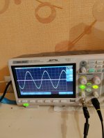
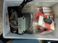
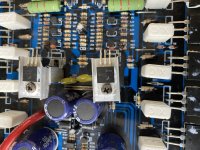
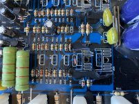
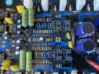
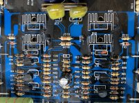
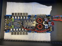
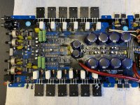
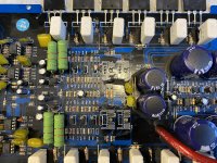
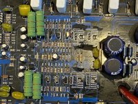
Hello good community, I am in a problem, since the stepped potentiometer that comes from stock in my Burson Soloist ha-160 died and I have to change it, the truth is I do not know what type of potentiometer I should put on it, I tried to contact the manufacturer and they told me that no longer have a spare. I have read that it is possible to put an ALPS Blue but the truth is I have no idea, the Burson comes with a cable to connect 3 pins to it, I will upload photos so that you can guide me, I would greatly appreciate them and also what recommendation would you give me.

Attachments

  • WhatsApp Image 2021-06-15 at 14.22.40.jpeg
    WhatsApp Image 2021-06-15 at 14.22.40.jpeg
    85.4 KB · Views: 225
  • WhatsApp Image 2021-06-15 at 14.22.14.jpeg
    WhatsApp Image 2021-06-15 at 14.22.14.jpeg
    75.3 KB · Views: 230

Class D vs speaker impedance

What determines whether a Class D can withstand playing in 4, 2 or 1 ohm?
The output filter will of course differently frequency rolloff and the coil in the output filter must be able to carry the current.
However, when the FETs "only" switch on and off, they can probably not be compared with, for example, a bipolar transistor in a class A / B amplifier ?

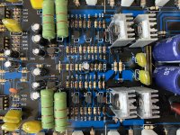
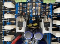
If a class D amplifier uses a pair of IRFB23n20d, does that say anything about how low impedance the amplifier can be loaded with?

The powersupply to the amp are 2 x 44 Vac (2 x 62 Vdc)

http://www.irf.com/product-info/datasheets/data/irfb23n20d.pdf

Low FQ Subs VS Mid FQ Subs

Hi, i'm new to installing subwoofers in my car. Not an SPL head, so i didn't decided yet if i will go with shallow subs or regular, aiming a bit to shallow 2 x 10" or 2 x 12", because of space and usability of trunk-cabin passage.


My current problem: when looking for subwoofers specs, i've seen a lot in the range of 30-200Hz and many others going to 600 Hz even 1000Hz.
Brands? probably something for budget like JBL or Dayton Audio aroun 150USD maximum a piece

Now, i am a bit intrigued which one should i go with, because i listen to music to normal volumes, very rare high volume

Should i go with a sub that's 200Hz MAX or with a piece that can go 600-1000 HZ?


At the moment i have a pair of JBL GTO 609C in the front (will be added A pillars midrange/widebands speakers) and planning to add a pair of woofers (probably without tweeters in the back doors) for rear bass feel, probabil will get them from 40hz to 1000hz.

Everything deadened anti vibration and sound absorbtion, will add a DSP but further on, will be the last piece of the puzzle

UPDATE: car is a VW Passat Sedan, maybe this counts when choosing the sub

Thanks

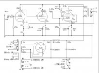
300B Amp Improvement Suggestions Needed

I have a pair of 300B monoblocks (currently running EML meshplate 300B 2.5V filaments). They have lovely midrange and plenty of bass in my system. I am consistently thinking the hum is a bit much and the top-end is a little rolled off. With 2.5V filaments, I get 5mV hum and with 5V filaments, I get about 6-7mV hum. This is with AC filaments and humpots.
The build currently uses a 6C6 into 300B as shown in schematic.
I am thinking of rebuilding these with the goal of reducing hum as well as increasing top-end extension a bit. Currently, they roll-off at about 10KHz.
I am thinking a larger chassis may facilitate changes so additional stages could be incorporated if needed.

Goals:
1) Reduce hum
2) Improve HF extension
3) Keep with early tube "flavor" but not at the expense of sonics.
4) Would like to keep the 6C6 driver as I have a LOT of nice examples of these.
5 Move to a 5V filament 300B as meshplate 300B 2.5V tubes are becoming very hard to source.

Any suggestions would be welcome.
Schematic below with changes to accommodate the 300B tube.

RCA6C62A3vers1.jpg

Why is floor bounce mostly ignored in commercial speakers??

Why is floor bounce mostly ignored in commercial speakers?

I've observed that most manufacturers seem to don't really care about the floor bounce effect in their designs.

Even with 3-ways where you could/should just place the woofer close to the floor and the midrange far enough from the floor for it to be outside the passband of both drivers.

So why is this?

Only reason I can think of is that closer center-to-center distance between woofer and midrange is of higher priority. Although the XO point between these two is usually low enough that it shouldn't really be an issue 😕

Making Square Waves?

Hi all

I am trying to find screen shots or measured data etc of loudspeakers producing a square wave.
This is turning out to be harder to find than I first thought.
I have seen many references to it, know first hand a Manger driver can, the Dunlavy’s are suppose to but when you read the website, they are talking about electrical summation and not measured response with the drivers included.
Can anyone point me towards results of two or three way speakers doing it in real life, that is a mic signal not a simulation.
Preserving time (and so waveshape) well enough to do this has been an interest for a long time and I am interested to see where I am relative to hifi speakers.
Thanks much

Tom Danley
Danley Sound Labs

Need help with crossover for Phenomax midwoofer and 3/4" Revelator

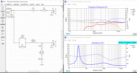
So I've had these drivers sitting around for the better part of a year and finally decided to try simulating a crossover. I don't have measurement equipment so I'm forced to go off manufacturer data. I used FPG graph tracer and XSim. It's my first time doing this. One thing that concerns me is the low efficiency but i think this is a given considering the efficiency of the midwoofer. The other is the 9.1 ohm resistor in the BSC circuit. It seems a little high when i compare it to other designs I see. I've attached a screenshot of Xsim. Any input is welcome!

Attachments

  • Phenomax-Revelator.png
    Phenomax-Revelator.png
    178.7 KB · Views: 294

Markaudio pluvia 7 7.2 small boxes

Hi, I'm thinking of building some small speakers to be used with the PC and then to be placed on the desk, I was interested in using markaudio pluvia 7 or 7.2 and I wanted rather small dimensions like these:

https://www.madisoundspeakerstore.com/pdf/markaudio-enclosure-plans/Alpair6M-BR.pdf

Unfortunately I have not found anything similar online ... any suggestions about it?
Thanks.

FOStex PS-3.1 sub/sat ills

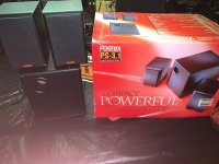
Hello. I bought this "kit"Fostex PS-3.1.jpg thru a Craigslist ad from a schoolteacher musician. It is in excellent condition. I'm seeking some suggestions on how to clean up the sound as it is perceived by me. I have other FOStex products that sound much clearer. I have not found any technical specs other than a sales ad. I have not removed the back of the subwoofer cabinet. How can I explain what I don't hear? My boat ain't floatin'. My totem pole needs artifyin'. I got no toe tappin'. Can someone please chime in? Thank You, civil6

Direct feed using optical cable

I have noticed there is an optical cable output (TOSlink?) on the back of my Sony CDP-CX350 and a matching input on the back of my Sony TA-F450ESD amp. I assume there is a DAC in the amp that I could optionally use for the CD player. I don't know if is will be an improvement or not but would like to have a listen to see for myself. As long as the plugs on the cable fit the sockets on the units are they all pretty much the same? Prices for a one metre length vary from about 5€ to 30€.

Opamp based power amp

Hello,

Starting a Zenquito Jean Marc Plantefeve 100W 4ohm , I wanted to edit it with OPAMP to boost performance, distortion , power supply rejection , thermal stability and load ...

First diagram : http://img.photobucket.com/albums/v637/zippy670/mf_p-amp_170_scaled.jpg

AOP choice : AD844 : 2000v/us !

By web searching I found JCB schematic De la puce à l'oreille - Acoustique et lectroacoustique who also used Lateral Mosfets but supplemented by bipolar power from a current to pull the best of each .

After having chat with CATSIANO , it seems that the Musical Fidelity P170 type diagram induce a phase shift close to the audio band and implies to curb the amp. I found the same thing on DIYAUDIO .

Here is what I was offered CATSIANO (still in draft) :

Using OPAMP bootstrapping and current mirror to ensure thermal stability.

An externally hosted image should be here but it was not working when we last tested it.

wien bridge mod

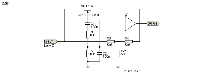
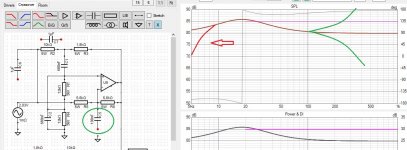
Hi, trying to mod the wien bridge bandpass filter:
- Parametric EQ

p150-f2.gif


I want so the rollof bellow the lower corner frequency to go bellow 0 db gain.

Up till now I managed to change the freq responce after the upper corner frequency (green graphs), bypasing R5 or R6 with C5
- attached

But I would like to obtain the red graph on my simulation.
This is going to be a vented cab bass response correction.
The frequencies bellow the filter boost are critical for xmax

Regards, Emil

Attachments

  • wien_bridge_mod_01.JPG
    wien_bridge_mod_01.JPG
    199.5 KB · Views: 267

Marantz PM-6A Bias problem

Hi

The Marantz PM-6A has an automatic shifting system from Class A to Class B. Class A and Class B run with different voltages (+-26,5 V and +- 63V) and different bias current (370mV vs 14 mV) in the poweramp.

Bias procedure is described in the Service Manual, page 3. While the bias for class B is easily adjusted, in Class A the bias stays far to high and with the trimmers (RL39 and RL40) I cannot reduce it further. The trimmers run out of way. 30 Watt Class A is also over the top so I would like to reduce it anyway - to three to five watts or so.

I have following ideas:

1. Change the values of the resistors/trimmers (RL39, RL 40) in the Class A bias part until I can reduce the bias to the values wanted?
But bias components for Class A and Class B seem to be interlinked (Service manual page 11) so I do not know whether the switching system will blow then or not work properly?

2. For Class B bias adjustment I have to connect two contacts together (JL15 - only on PCB not in schematic - and JL12). Can I leave this connection permanent and bias the Class B system a bit more or will the amplifier blow in the end?

More ideas? What should I do?

Audio system x ion 280.2 no audio in speaker

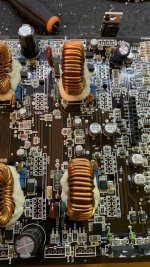
Goodmorning everyone ! I have a problem with a system x ion 280.2 audio amplifier! The amplifier turns on but no audio comes out in the speaker. I have measured all the mosfets and transistors present and I have no damaged devices but the thing I have seen is that I have no bias voltage on the mosfets! Do you have any scheme or advice for me?Sorry for my bad English Good job everyone

Crimper Dies For Molex KK

I have a 'Draper Expert' Crimper frame and would like to use it to crimp the pins from the Molex KK series. The Draper frame looks more-or-less identical to a raft of other crimpers including those from Klein and Wirefy.

So I should probably be able to use their dies in the Draper. But I have no clue from looking at the die specifications which I should choose. Can anyone explain what I should be looking for?

I know I could buy another crimper tool, but it offends me that I have a frame that would take other dies and can't make use of it. I'm prepared to take the hit if the die I order doesn't fit, but I'd at least like to know I was ordering the right one.

I've had a rummage though other threads here and, so far, haven't found anything that'd help.

SAKSA85 Pre amp suggestions

Gday All

Have had my SAKSA85 for about 3 months now and absolutely love it. Running a pair of Spendor LS3/5a, KEF Concertos and Pioneer s-910 Handles them all with ease and sound fantastic

Have been using my PC into a schiit DAC into the SAKSA. I'm considering running a conventional pre amp to run more inputs, phono pre amp, volume control and just general safety of operation.

Can anyone advise on any good experiences with pre amps and the SAKSA85

Edit: I purchase a Schiit SYS, which is a small volume control module which can switch between 2 inputs if required. I felt it dulled the sound slightly and the manner in which it controlled the volume didn't feel linear. i was often holding the volume at almost full blast for not very much sound.

Thanks in advance
  • Like
Reactions: AKSA

Speaker pop - only for SQ experts

Hi,
I'm having a pair of JBL GTO 609C and starting to build my car audio System. They are connected to an EDGE 350.2 200w x 2 4ohm.
I also have a Ground Zero GZHA4120X 4x85W and JBL GTO 75.4 (1st gen) 105w x 4. for the rest of the speakers and sub that will come to install. Maybe i will put the GZ for the front even it's not that powerful as the Edge, but i think is having more SQ.

i've played around with my Alpine ute 72BT HP filter, but even at 120hz, if i turn all the way up loud they get to reach max and pop. It's true that i have my bass +3 level, mid +2 level, and MX at 3.

I was just doing a simulation of how will the front sound when i will install a subwoofer.
Also i have my Spotify/ Galaxy S10+ EQ custom to a clear sound (not over 0dB in the bass) just a litte over 0dB from 1kHZ up depending the frequency, for a CLEAR sound.
I like the sound to be good not flat. Flat music is awful.

Did this because the DSP will be the last piece of the puzzle being so expensive (a good one like Helix/zapco/Audison)
Building separate enclosure for the woofer is not possible is my daily and can't cut the door panel (VW passat has a middle panel with window mechanism that removes completely).
Just deadened the doors with vibro and silent coat on all 3 panels outside metal, window mechanism panel and interior panel).

I was just thinking if there is a way that coud stop the speaker bottoming out on lower FQ like 60 or 80hz?? This would be very good if possible.
Maybe this can be achieved with an amplifier having higher Damping Factor?

It's weird because music being dynamic, there are songs like hip-hop that have bass and can make speakers pop and other music genres like rock or pop that can crank the volume up to 100% max and no poping.
Also there are songs that have bass that can't even be reproduced by the speaker (i think) and makes the speaker pop a lot.

What's your guessing about stopping this phenomenon happening in the lower FQ?

Ifinity PS-10 Sub: Need Help With Diagnosing Voltage & Heat Issue

Hi DIY friends,


I need someones electronic trouble shooting expertise in helping me diagnose an Infinity PS-10 subwoofer plate amp. I'm trying to fix this subwoofer for my younger brother.


Unit powers on (green LED lights) and changes into (Red LED lights) stand-by mode.


When an analog sound source is presented the unit plays for about 30 to 40 seconds and the sound starts to distort.


Upon first inspection I checked for any obvious signs of trouble with bad looking capacitors or fried components and nothing was apparently obvious. So I got my laser infrared temp gauge and immediately started examining individual components and when I lit up Q3 and the associated resistors R9A, R9 I observed 160 degree temps fast approaching 200 degrees Fahrenheit.


Measuring voltage from resistors R9A, R9 read 39.1 VDC


I then turned my attention to Q2 and the associated resistors R6, R7A. Temperature readings from those components was around 78.1 degrees Fahrenheit. Voltages on resistors R6, R7A were reading 51.3


I have replaced all the polarized caps in the amplifier section with Nichicon with the exception of the two large 3330uf 80v.


Capacitors Replaced:


(Two) 22uf 10% 25v
(One) 10uf 10% 25v
(One) 47uf 10% 25v
(One) 330uf 10% 16v
(One) 4.7uf 10% 50v


I have a LCR meter and pulled those two large caps and the readings were very acceptable.


I don't have a schematic and the only document I could find was the user manual. So I really don't have much to work with as far as factory specs for this unit. My assumption at this point is that Q3 is the most likely source for the problem, but I can't make heads or tails as to what the actual part# is as the printing on the transistor is micro print and not legible.


Any input from the gurus here would greatly be appreciated as my electronics skills are on the equivalent of a parts swapping monkey...😛

AKSA 55 power supply options?

Greetings all,

I have been using AKSA 55 with a lab power supply, but I now intend to build the AKSA as a pair of mono-blocks, perhaps eventually being built into a speaker enclosure.

I was wondering whether I should use linear powers supplies, i.e., rectifier, transformer, capacitor filters, or, given the advances in switched power supplies - efficiency - use these?

Any recommendation both regarding the different concepts, as well as specific parts would be appreciated.

Kindest regards,

M

Synergy, low diffraction, on wall speaker wanted

What I want, is a synergy/unity horn speaker with low diffraction and that is designed to be placed on a wall inside a room. I have conctrete walls. They have to be on the wall because I need to dance.:emoticon:

As I don't have the skills to design such a speaker and I don't know any exist, I'm asking the experts here to help me design one. Or if there is one post a link.

My design goals:
No audible distortion up to 95dB spl.
Frequency response reasonably flat from 80-100Hz to 15-20kHz. (I'm using the multi sub thing, so no need to go lower)
And of cause constant directivity.
I have on wall speakers that have a very wide radiation pattern, so these can be narower to compare the radiation patterns.

Best Bill.

Hifonics brz2400.1

Hi I have a hifonics Brutus 2400.1 amp my problem is when I turn my truck on the radio and amp turn on fine and plays fine but when I turn truck off everything shuts off like it’s supposed too but after a few minutes sometimes more the protect light blinks once then the power light comes on and stays on. If anyone has any ideas on what this could be I’d greatly appreciate the help

RTR EV9 tweetrs ??

any suggestions for a good tweeter replacement? I also need to port these speakers to get any bass out of my new woofers Goldwood GW-8PC-8 8" Delmar Series Heavy Duty Woofer 8 Ohm

What size port will I need with these woofers? Boxes are around 1.4 cu feet.

Tweeters? DO these work Eminence APT 200 Super Tweeter with Bi-Radial Horn 90 x 90
Or high end tweeters http://www.parts-express.com/fountek-neocd35h-horn-loaded-ribbon-tweeter--296-703

I do not know how to upgrade X overs, do I need to do this to improve the speakers? They also lack banana plugs ...🙁

I mostly watch movies, listen to music too sometimes:up:

Anybody use DSP in their setup?

I have been using DSP since my solidstate days, and have enjoyed adding it to my tube setups. Anybody else use DSP in front of your tube amps? I had Chromecast audio feeding a miniDSP nanodigi, which went to Khadas tone board DAC and then to the 8900. I wanted to experience 24/192, so I replaced the CCA with raspberry pi 4 running Moode audio last week. I use the Camilla DSP inside the OS now, feeding the Khadas tone board (I upsample everything to 24/192 in Camilla DSP). I accidentally seem to have stumbled into audio nirvana. This setup through the 8900 and my open baffle Lii audio f18 is just magical (I DSP'd the system ruler flat from 25 Hz to 16 KHz at my sitting position). I know purists look down upon DSP, especially before tubes, just curious if anyone likes DSP.

Passive XLR line mixer?

Hi DIYA!
At risk of sounding ignorant, I'm looking for info on building a truly passive mixer with 4 XLR inputs, and one XLR output, to run a battery powered PA for busking.

For those pesky, "No power supply available within 200-feet." situations.

I have the battery powered speakers. (Which have PLENTY of headroom to lift a quiet signal.)

I just need to know how to wire up a simple signal mixer with no frills, and doesn't need to amplify any part of any signal. I understand all adjustments would be cuts, and no boosts. That's 100% cool!
I know it's more than just a set of volume pots and jacks in a box. But I don't quite have the knowledge on what kind of load a mic-level signal places on the output, and how each load affects the next. (From what I've read, that's a real issue I'll need to work around.)

Any info would be a huge help, and greatly appreciated.

Installation of Lclock XO on VRDS-10, how?

Hi all.

I have Teac VRDS-10 that I what to use my old Lclock XO and a separate power supply called "XO2 power supply" in. That works well for the Lclock XO.
Wile I know how to do it on say a Teac T-1, as I have that servo board, I am a little unsure on the servo board of the VRDS-10. It's kind of similar in places, and yet there are many differences.
When installing the clock in T-1 or similar, I unsolder the crystal X51, the C51 next to it and C55, which is an orange trimmer close to it.

On the VRDS-10, there is the same X51 crystal, the same c51, but no c55.
But on the other side of the crystal is another c52 capacitor. Both the C51 and C52 are very small ones.

So, on the VRDS-10, and using the external power supply, I suppose I should unsolder the crystal X51, the C51, but also the C52?
I will then only solder in the signal+ in to the crystal's one end and the ground in to the one end of the C51 as per Teac T-1.

Anything else to do? Such as unsoldering C52? Other components?

I am not educated in electronics, but can follow a guide 😉

Any comments and help on this is most appreciated, so I can get it up and running 😉

On LC Audio's webpage is a guide for the Teac T-1, Copland CDA-288 and others, and that guide is the one I've been following on the Teac T-1 and a Copland.
There is also a guide for Teac VRDS-10, but that guide is the same word for word, and there is no such thing as for example an orange trimmer on the servo board on a VRDS-10... So I guess there's been a mistake years ago in the guides.

I called them today, but to no avail. They just told me they didn't know the way to do it. I think they were just not interested.

Kind regards,
SFC1000

First sub.

Hey all. First post in the speaker section.

I have 4 5 1/4" Energy woofers that I want to build a box with for 30Hz and lower. I'm not looking for miracles. It's an appartement.

They will eat about 200W total. I'm thinking active crossover for simplicity.

Do any of you have a box design for such a thing? The last time I built a box with 4 drivers, it looked like a stove.

Thanks

IC identification - DDaudio sound board

Hello,

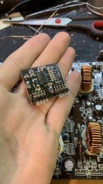
I need help to identify the IC on the control board (DDaudio SS4a). The sound mosfets are 2pcs IRF640. Something tells me it will be IRS2092S ?? Does anyone happen to have a schematic or parts list from this device? The amplifier has been heated, a lot of SMD capacitors have burned out and I would like to find out their correct values 😡

Thank you for your help and your Time! 🙂

Attachments

  • DFED9BD1-C154-477F-BC86-D5405B2360F9.jpg
    DFED9BD1-C154-477F-BC86-D5405B2360F9.jpg
    634.3 KB · Views: 130
  • 02AD4163-3A4E-4F0C-9777-87DF196D98B6.jpg
    02AD4163-3A4E-4F0C-9777-87DF196D98B6.jpg
    359.3 KB · Views: 133

Marantz cd73 stops working after short time.

Hello friends,

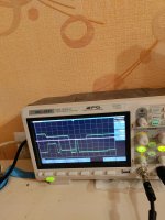
very interesting case.Marantz cd73 reads disk ant play .After 2-3min the disc starts to spin slower and stops for a while.If player cold ,play longer about 1-2 tracks.playing longer stays off the power.without switching off the power, after restarting, restarts, plays for about 20-30 sec.I have no any ideas.Power supplays voltages are ok.HF signal are ok.I tink problem is in decoder board (this player has sony chips),but I can't find the fault.the oscilloscope shows a distorted signal before stopping.Maybe you have any ideas?Thank you.

Attachments

  • IMG_20211027_204629.jpg
    IMG_20211027_204629.jpg
    552.4 KB · Views: 80
  • IMG_20211027_204435.jpg
    IMG_20211027_204435.jpg
    538.8 KB · Views: 81

Diagnosis needed. Crossover or woofer problem?

Pair of Musical Technology Falcon speakers measure 6 ohm one side (as rated) but 9 ohm on other.

Lower woofer on the high impedance side moves when powered but with much less force and excursion than on the other side.
Each has 2 woofers in separate enclosures with tweeter between.

Crossover (4th order I think) has 10 caps and 3 inductors with no visible damage.


Anyone able to diagnose this?

So, how to measure impedance?

So I saw Dayton Audio has a DATS V3 out. Seems nice, and not expensive! Yay! Ooops except for the "Windows Only" part and I don't have a decent WinTel machine any more.
- Are there automated alternatives for Mac/iOS? (I don't want to homebrew anything, don't want to spend that much time)
- If not, how crappy/cheap of a Windoze machine would I get away with to run this? (I have some at work but none that have Admin access to install anything, grrrr, and nobody knows how to fix that, no tech any more).
- And if I did scam a WinBlows machine, would you get DATS or something else?

Nutube B1 T7-T8 voltage.

Hi All,

I have been using my Nutube B1 for about a week. It sounds great. It is not doing anything odd. I do have a question about it though. When I checked to voltage between ground, T7 and T8, the recommended level is 10 volts. Mine will not go that low. I have set them both the same at 13.47. That is the lowest one channel will go. Does anyone have any ideas for why that might be? Am I risking problems running it with the voltage at this level?

Thanks

Need to do a mic to speaker audio passthrough in raspberry pi zero

I need to do a microphone to speaker audio passthrough in raspberry pi zero. I use a USB sound card attached to a USB hub with a raspberry pi zero board.

Surprisingly I can't find good working sample codes for something I had thought somebody must have done already, and nothing I have tried so far has worked, so here in hopes of getting some expert opinions

I tried using ALSA's C API to make my own program, but it's too complicated and seems to have a very steep learning curve. I tried PulseAudio and it gives distorted output. I tried libsoundio and it gives broken output. I finally managed to do what I needed to do using RtAudio (which conveniently also has an audio passthrough sample code: The RtAudio Home Page) but it turns out if I keep the audio passthrough program running long enough the output starts getting distorted for no apparent reason. I have tried playing around with audio frame buffer size, sampling frequency, channel count, and nothing works. I can't tell if it's something wrong with my program or the library itself has a problem. I tried using Audio classes from QT but a very basic passthrough program I came up with using this gives a distorted output. For something that's so popular I don't understand why QT themselves don't provide an example of how to do this.

I have done something like this before for a Windows 10 program. I thought it would just be a matter of finding the corresponding audio functions for doing this in Linux, and I should be able to make something usable for raspberry pi. Apparently not the case.

Sorry for the long'ish rant. I hope someone can answer the following questions for me:

1. Can anyone provide a working audio passthrough sample code in Linux/raspberry pi OS using C++? I would prefer if it uses callbacks and not blocking function calls. Something similar to the RtAudio sample code I linked above. Or if anybody knows how to fix my problem with RtAudio it will be a great help.

2. Isn't ALSA the lowest level software between the OS and the sound hardware? If my OS has ALSA shouldn't that be enough to do what I explained above? Where does Pulseaudio come into the picture here? Is it a replacement for ALSA or does it work on top of ALSA, like RtAudio is supposed to work on top of ALSA?

3. I am looking at the JACK audio library (Home | JACK Audio Connection Kit), now that the other things I tried did not end up working. Should I understand this as something similar to RtAudio? RtAudio's website says (The RtAudio Home Page) it can use JACK as an "Audio API". What does being an Audio API mean here? I'm guessing this means if a computer has RtAudio but doesn't have ALSA/JACK then RtAudio will not work. But isn't it true that if a computer doesn't have ALSA audio will not work on it at all? Is JACK something that works as a replacement for ALSA or something that works on top of ALSA and provides us an interface to ALSA? the wikipedia page for JACK says "JACK can be used with ALSA, PortAudio, CoreAudio, FFADO and OSS as hardware back-ends." So does that imply JACk will not work without ALSA? Where does it fall into the hierarchy?

Again, sorry for the long post, and thank you if you've read this far. Any hints that will help me go in the right direction will be greatly appreciated.
Autotek A1800 - 1Channel, burnt resistors in the output-stage

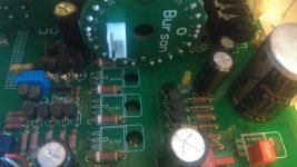
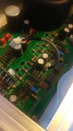
This Amp got some shorted transistors and burnt resistors in the output-driver-stage.


I replaced the Transistors and am now lost with the values of the resistors.
Positive and negative side has the same burnt parts.


Maybe anyone has a schematic or a picture of this section. Would be very appreciated, thank you for your time.

Attachments

  • IMG_9608.jpg
    IMG_9608.jpg
    1 MB · Views: 95
  • IMG_9624.jpg
    IMG_9624.jpg
    984.6 KB · Views: 83
  • IMG_9626.jpg
    IMG_9626.jpg
    986.4 KB · Views: 67
  • IMG_9635.jpg
    IMG_9635.jpg
    1,011.8 KB · Views: 73
  • IMG_9639.jpg
    IMG_9639.jpg
    1 MB · Views: 75
  • IMG_9643.jpg
    IMG_9643.jpg
    1,007.7 KB · Views: 53
  • IMG_9651.jpg
    IMG_9651.jpg
    1 MB · Views: 70
  • IMG_9652.jpg
    IMG_9652.jpg
    1.1 MB · Views: 85
  • IMG_9653.jpg
    IMG_9653.jpg
    1 MB · Views: 65
  • IMG_9654.jpg
    IMG_9654.jpg
    1 MB · Views: 50

Different Gain On Channel 1 and 2

Hi,
I've recent bought an used amplifier, MAC Audio 4000D, 4x150W 4om, and i am a bit concerned about something.
If i set the gain by multimeter, i get different values between ch 1 and ch 2.
For example i've set gain for ch1+ch2 24.13V, multimeter cables in ch1, and i measure 25.47 V on Ch.2. So a difference of 1.34V in the output.
I've set gain for ch 3 + ch 4 and they bot stay the same 23.94V set on ch3 and ch4 also got 23.94V (equal)

Also, if i touch the Full/LP/HPswitch the amp kind of goes to the other setting. For example if it's in HP and i touch the switch (but not moving to select) it switches to LP (being the nex select position), but only touching or moving a little little bit with a screw driver's head.

Is this a thing to concern for getting different power to ch 1 and 2?
Should i get back to the seller and sort things out probably if he agrees to get my money back?

Thanks

45 Tube recommendations

Hi

I’m in the process of building my first 45 tube amp.

I’d like to give it a try without spending too much, so something with a good ratio price vs performance would be great.

My OPT will be Edcor 15W so this should gives you an idea of the overall cost of the amp.

Would you have any recommendations for the 45 output tube, brand, etc.?
They don’t even have to be test great, just good would be ok for now. If I don’t really like the overall sound at least I won’t have spent a lot. I’m aware that the overall sound of an amp is not just based on the output tube but it still has an influence.

Maybe drop me a PM if you feel like getting rid of some 45 tubes you don’t plan on using.

Thanks
Eric

RH300B 12W with 1% THD

AK posted his latest amplifier based on the 300B on his blog. I don't want this thread to turn into yet another "us against them" bash-a-thon 😉, so please limit your comments to the specific question below:

How do you get 12W with just 1% distortion using a single 300B?

Here is the schematic and simulation results from AK:

RH300B+V2-2a+final.png


My simulation result was far from AK's,but pretty typical for a SE 300B amplifier - at 5W, the THD is ~4.5%, perhaps my tube models are messed up or quite different from the ones used by AK?

I'm on the road now, but I will try some other models when I get home, in the meantime, perhaps some of you sim-jockeys could run some sims to verify the results or better yet if anyone has actually built one already, please post the test results here.

TIA,
Jaz

Ford/Philco Tube Radio Power Source?

I have restored a Ford/Philco car tube radio from a 1930s Ford Coupe. The Car originally had a 6-volt system, but has had a type of battery installed in it that apparently changes to 12v to use an aftermarket 12v starter and then reverts to 6-volt afterward. I didn't know that when I got the radio and I am not familiar with how those systems work. Now I'm concerned that he'll crank the car and blow the filaments in all of the tubes by hitting them all with 12v. Could of course be sure it's turned off while cranking, but accidents are almost certainly going to occur eventually. Do those fancy batteries supply 12v to the entire car during startup, or just the starter? The car is in a different state or I'd just go check it myself. I guess what I'm asking is if there is a "proper" method of handling this type of situation. I thought about maybe getting a 6v SLA or lithium battery pack just for the radio but I'm wondering if the alternator would be an issue since the car is wired for positive ground. Don't want it trying to charge the battery pack. Anybody dealt with this?

Stupid Cheap Line Array

All,

I have another dumb idea and I'd like to know why it wouldn't work. Or it might work, but something tells me this is too easy...

https://www.madisound.com/store/product_info.php?products_id=8988
Case of 30 for $60...

I'm thinking, for my intro into line arrays, that this would be a near-perfect driver. It's not one of those nice clean 3" drivers, but it has more bass, and it's still pretty small. It looks like it'll go low enough to cleanly mix with a sub. The harmonic distortion curves seem ok, but I also don't really have a reference as to what's good and what's bad.

So, the design is that driver, along with the (in)famous Goldwood GT-1005. Actually, I was planning on using the GT-1001 since I think the flush mounting looks awesome. Of course, I thought, for some reason, I had a frequency response graph for these tweeters, but without one I think I may have to pass..

The plan is to wire the 5.25"ers either 3 or 4 in series, those sets in parallel (16/side). If I ran this as a free-standing speaker, I'd run one set of 4 drivers as a 0.5 way for BSC, but I'm also thinking about making these into a Murphy corner-line array design. As sensitive as this tweeter is, I was thinking about running a single driver it in the middle of the array, a sort of a MMMMMMMMTMMMMMMMM design. Is this problematic?

I haven't thought much about the crossover yet, it doesn't seem like it would be very tough. I've been experimenting with 1st/2nd order low/high and 2nd/2nd. I'll probably need some other woofer correction, especially if I cross it pretty high, but it seems like these drivers are pretty damn usable for the price.

Let me know what you think.

Greg

Forté Audio Model 3 Hum

Hi guys,

I bought my uncle's setup about a year ago. It's as follows:

  • Amp: Forté Audio Model 3
  • Preamp: PS Audio 6.1
  • Speakers: B&W 804 Matrix

I had the preamp checked and everything was fine. I also had the amp checked and asked a tech to change the bias pots. I then adjusted the bias to around 35-40mv iirc which means the heatsinks are now running at around 45ºC each per Nelson Pass advice.

Everything's good and it sounds really nice, but I have a hum problem since the beginning that the tech said he couldn't find at the store. Now, this is my first setup with a dedicated solid state power amp so I don't know if any kind of hum is to be expected or if it should be 100% silent.

A few things:

  • The amp has a mechanical hum that is kinda strong as soon as I power it up and in a matter of seconds fades out to being just there. It's audible if I put my hear next to it, but not as loud as it is when I first turn the amp on. Please note that the hum fades out in 2 seconds;
  • The speakers have a hum too when the power amp is connected. It seems like the same frequency of the mechanical hum, but I can't be sure. It's close though;
  • The hum may be heard through the speakers even if there's nothing connected to the inputs of the amp;
  • The hum gets louder when the preamp is on, like it's amplifying it. But it does not go up in volume if I turn the gain up on the preamp. And it's also independent of source;
  • I can't really hear the hum when I'm sitting down around 2.5/3 meters away from the speakers, but if it's completely silent and I get close to them, it is noticeable.

I made a video showing the hum with the preamp + amp powered on. It sounds a lot more louder in the video than it actually is because I put my phone just next to the speakers.

Forté Audio Model 3 Hum - YouTube

I'm sorry if there's a way to embed YouTube videos, but I don't know how.

Now, I'm no expert in electronics, but I'm super comfortable with a soldering iron. I'm not saying that I'll be the one fixing this thing, but if you tell me I need to change a couple of capacitors, as long as I know where to get good ones (I'm in Europe), I might just go for it.

If not, I'll need to find a different tech because the last one said he couldn't find any hum 😕

Thing is, I need your opinion about this. What could it be, is it possible to narrow it down to a component? I'll say again, the amp sounds really really good, but I don't know if it could sound even better. The fact is, a hum is there, so unless it is to be expected, something is not right.

Thanks in advance!

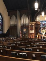
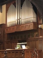
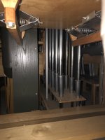
Pipe organ

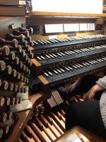
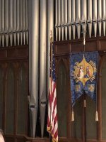
It was my sons wedding today at a pretty old church in Birmingham Alabama built in 1889 or 1898
They have a pipe organ there, that was made in the year 2000 and it took them two years to make it and then fly it in from
France. This thing has 11,000 pipe. Yes I said 11k of pipes. And the sound it WOW
Here’s a few pics I was able to get before I got Caught lol. I have some more so when I get home I will post them
IMG_2578.jpgIMG_2582.jpgIMG_2622.jpgIMG_2617.jpgIMG_2580.jpg

Audio System X-Ion 280.2

Got this amp for repair. Everything working normal, but i have crackling noise on one channel.

1 RCA on left channel plugged, left channel nearly ok, right channel also playing noises, which belongs to the music.
Both rca cables plugged, more diaorted on both channel.

All filters of, if i press the button for hp or lp, and then deactivate a filter, for about a second everything plays normal.
I expect the TL072 at the input.

FS: Musical Technology Kestrel floor standing speakers Rosewood, UK.

Lovely pair of very underrated speakers for sale.
In really good condition, no dents, marks, creases to the tweeters or woofers.
In nice rosewood finish, with the optional baseplates.
These speakers beat some much more famous competition
They have in-house designed/built aluminium woofers, vifa dome tweeters as used in many of the PMC models of the era
4th order discrete crossovers etc

Much prefer collection, but can securely pack and send.

Asking just £150,
Unbelievable value for money!
More photos available, just ask.
20210711_175129.jpg

Loud buzzing = Impedance mismatch?

I bought a cheap NobSound amplifier for my passive Polk subwoofer. Works fine.

I also purchased a pair of Fluance Ai6i speakers (highly recommended BTW). They sound fantastic!

Now when I connect the sub out (filtered) from the Fluance to the Nosound audio in, all I get is a loud buzzing.

My possible options so far are to get the Fluance compatible powered subwoofer and return the NobSound amp and then have a useless passive sub...

or

buy an RCA splitter and run both inputs directly from the audio out from my old Sharp TV. I don't see why this won't work, but then I would have no remote controlled synced volume thru the Fluance which is what I am striving for.

I am waiting responses from both companies, but is there anything I can do in the interim?

Chip Amp based on the topologies from Yamaha MX-10000 and Quad 405

If I have a look to the simplefield schematics, I guess, that it must be possible, to create an amplifier with appropriate audio power amplifier chip for the class A/B parts and simple single ended solutions for the class-A parts. What about this idea?

Attachments

Acoustic timing reference for driver time alignement in REW

I'm trying to physically place two drivers on a baffle so that they are time-aligned. To do this, i have first made a best guess, built a baffle with a certain offset, and measured each driver using acoustic timing reference in REW. The issue is that neither phase nor calculated IR offset changes at all if i move the baffle several cm towards the mic. It looks like all i'm getting is the minimum phase.

Is this a limitation of the acoustic reference-method? I'm using a separat speaker as reference.

2SC5198 - A1941 Replacement

Hello Everyone...

i'm having issue with finding 2SC5198 and A1941 so i replaced 2SC5198 with 2SC5200 and A1941 with A1943 and they are running by
i didn't change these C2073 And A940
also there is A1013 transistor i didn't change that either i don't what it does but both side a1013 Getting extremely hot after few seconds,
on the left side there is Hum sound coming after 3-4 seconds when i check the output it shows Minus 9.4 volt from the speaker out before that voltage around 0.03v

sound has no issue in right side but A1013 Heating like a hell 😀
what could be the problem?

There is no diagram 🙁

Does anyone have a service manual or parts list for a Cambridge Soundworks Newton P10

I have a Cambridge Soundworks P-1000 and it’s dead. Amp won’t power on at all. There is no visible damage to any parts. The control module powers up fine. It’s an indigo bash 1000 watt amp board. The fuse is not blown and there are no shorts - using a dbt. The main power filter caps are charging but the power on led doesn’t light up at all and there is no voltage to the pins.

I have replaced the main power switch, mosfets, power diode, bridge rectifier, all power transistors and all electrolytic’s on the amp and interface boards. Still dead as a door nail.

Something is keeping the power supply from switching on. Any ideas? Without a service manual or parts list it’s like playing pin the tail on the donkey.

Standalone multiple EFX box

Hello!
I plan on building a standalone multiple EFX unit with delay, reverb, and chorus. This would recieve audio signal from an unbalanced line mixer. I've been looking on a lot of EFX kits/PCB's for building guitar pedals, would I get into trouble with impedance if I were to use these kind of circuits?
Since the audio is coming from a mixer I'll be able to dampen the signal so it isn't too loud, would that solve the problem with the signal not being instrument level?

Thanks,

TA

I want to upgrade some parts in my YBA amplifier. Suggestions!

As the title states Id like to upgrade my YBA YA201 integrated amplifier. It has developed a hum in the left channel and I'll be taking it to my local audio electronics tech to get it fixed. While it's there I thought I'd upgrade some of the parts to higher quality, better sounding ones as this amplifier was built to a price point (it's their YBA Design series).

Which parts in a solid state amplifier are the most critical as far as sound quality is concerned?

Mladen

Hygeia Electron Co. - AMT's and Planar Ribbon tweeters

I have for sale AMT and planar ribbon tweeters, made by Hygeia Electron/Electrical Co, LTD. Excellent build quality, consistency, and performance, low distortion.

Also available to those who purchase tweeters are extra diaphragms as well (for purchase).

uc


As you can see, my AMT's have an extra nice machined aluminum bevel on the faceplate, not available anywhere else.
uc


uc


uc


uc


uc


MASSIVE heat sink

uc


Extra Diaphragms
uc


Everything is brand spanking new. Original receipt:
uc

uc


Current quantities available and Prices (quantities & prices subject to change!):
uc


As you can see from the original receipt and my quantities remaining chart, some of these are already gone and I just received them! Please contact me for a quote, or for questions.


I am not set-up for international shipping. The only way I would ship internationally is setting up an Ebay auction and using their Global Selling/Shipping program, that way the delivery of the item would rest on Ebay's hands.

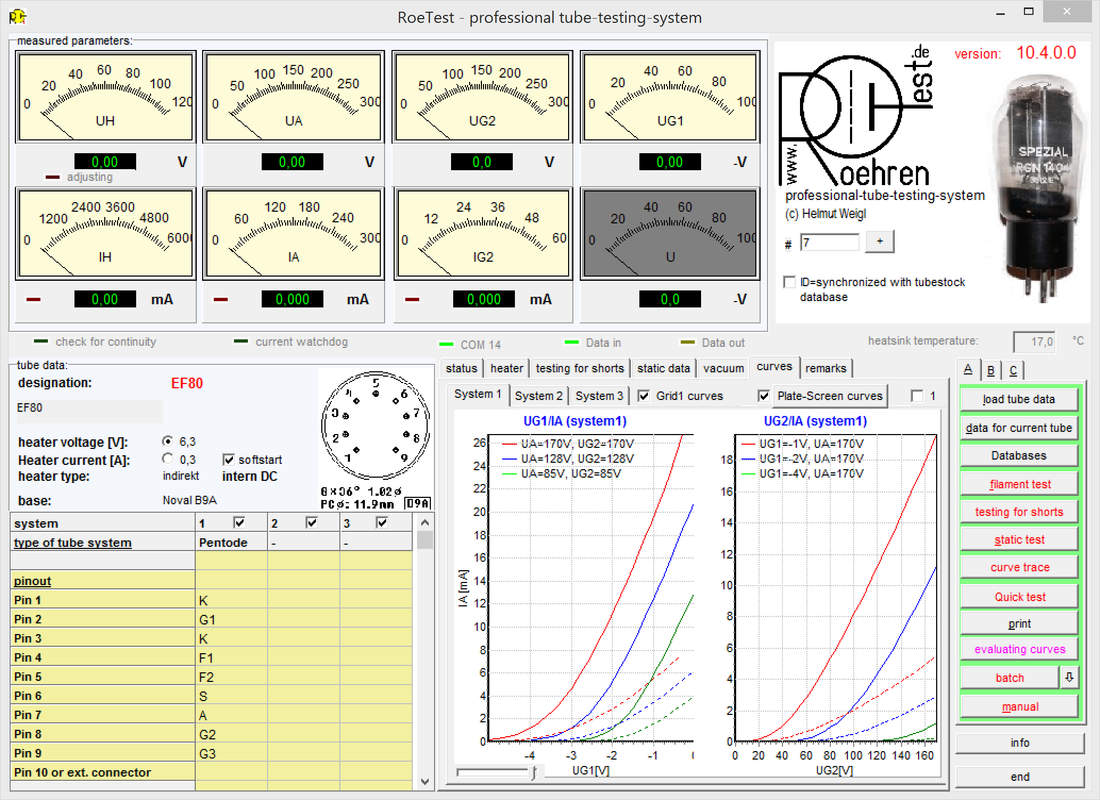
State of the art German diy tube tester/Curve Tracer

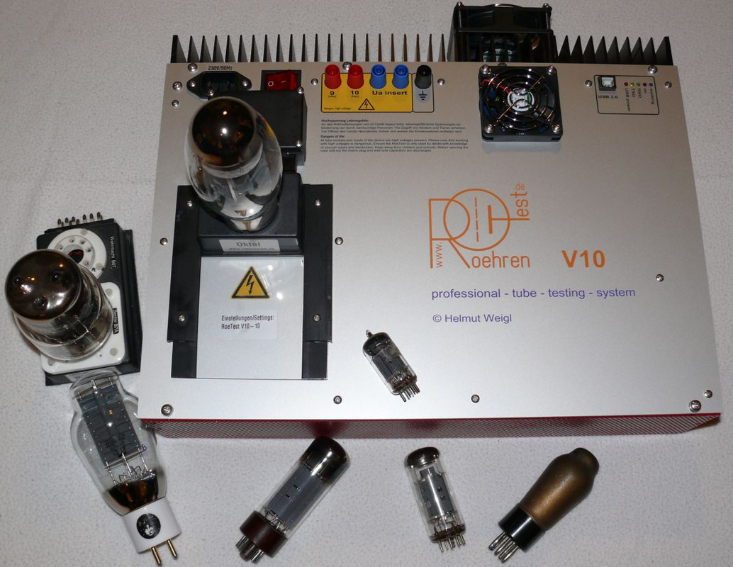
STATE of The ART
modern computerized tube tester - tube curve tracer


All the settings required for the tests are set automatically from information in the data base or can be entered on the screen by the user.

Tests include:

Shorts test
Static Tests (including current, gm, Rp and mu)
Characteristic curves (grid curves and plate curves)
Quick test
Emissions tests
Batch testing
and more ...

WE will prodive Technical Support

Need Help/Schematic Fixing Sunfire Signature Subwoofer Amplifier

I have a Sunfire Signature Subwoofer that has a few broken wires and capacitors, but is easily fixable provided I can get some help. Does anyone have a schematic for the subwoofer amplifier (with component values)? Would anyone who has a Sunfire Signature like to help me fix it by sending me pictures or sending me component values from their amplifier?

Thanks,

Chris
Projects by fanatics, for fanatics
Get answers and advice for everyone wanting to learn the art of audio.
Join the Community
507,760
Members
7,887,257
Messages

Filter

Forum Statistics

Threads
406,173
Messages
7,887,257
Members
507,760
Latest member
The Fink