Upwards aligned open baffle? ( pop box meets open baffle )

Hello all!

Since reading that open baffle sounds nice and has a better radiating pattern I've thought of merging the Carlsson inspired pop box with the open baffle concept:

It would be used primarily for music listening on low volume, no earthquake capable sound needed 😛

Dipole/Ripole subwoofers to handle up to somewhere 100 - 300, or as high as they can handle while still performing optimally.

Then do an open baffle with upmounted full range driver surrounded by four inwards mounted tweeters to help from about ~ 4-5 khz and upwards, for if I'm not mistaken the FR driver would in these higher frequencies have inadequate dispersion.

attachment.php


The baffle would stand on for example on legs and stand 50-70 cm high.

The idea is to create an open baffle speaker without a soft spot inside the room, I move around in the room and want to enjoy the sound everywhere.

MiniDSPs would be used to handle sub -> OB speaker crossover and EQing while the FR and Tweets would be passively crossed, maybe active there too in the future though.

Do you think this could work or is there a better existing solution that would also give me softspot-less sound? Since open baffle supposedly already have a good spread would it still be advantageous to flip it horizontally or is it better to have the baffle vertical as normally done?

And if it would work, approximately how large would the baffle have to be? Would it have to be gigantic or can one get away with something in the line of 25 x 45 cm?

// Olle

EDIT:

This might be better placed in "Multi way", so if it should and some mod sees it maybe they can move it? =)

Attachments

  • pop baffle.png
    pop baffle.png
    23.5 KB · Views: 894

Taramps HD8000

Hi Guys

Working on a HD 8000. Amp came with a blown power supply. Customer did inform me that he given amp to another tech to repair and it played for about 5secs or less and then amp went up in smoke. On opening the unit i found that the other tech used 65n06 instead of IRF1404. I also found all the 10R resistors to be open. I replaced all the FETS(all from the same batch) and the all the 10R as well as the 4x IR4427 chips.

Powered unit and only to find that all 3 LEDS light up. The blue LED is brighter that the others as shown in the picture below:
IMG_20210702_170313.jpg

SO next I checked to see if I was to see if the IR chip was getting power, which it is on pin 6. I also checked to see if I was getting wave form from the pic to the IR 4427 but nothing coming into the chip. I traced back to find that wave form comes from Pin 5 and 6 of the PIC controller. No matter how slow I turn down my scope i get nothing from from pin 5 and 6.Here are the pics of pin 5 and 6:
PIN 5 of PIC.jpg
PIN6 of PIC.jpg

I am getting my 5 volts to power the PIC.

Any ideas if there is something else that is causing the problem or is it just the PIC that is gone faulty.

Here are some pics of the board:
Main Board part 1.jpg
[/ATTACH]

Attachments

  • Main board part 2.jpg
    Main board part 2.jpg
    847.2 KB · Views: 258

Music for Oct 31

Greetings!

I spent more time than I care to admit putting together two Halloween Spotify playlists. I'd like to think I did a better job of curating than what you'd find on the likes of buzzfeed, etc, so I thought I'd share in case they are useful for others.


The list is typical pop culture stuff, drawing from movies about Halloween, magic, etc, as well as some songs that are more tangential.


The short (2hr) list, customized for Trick-or-Treat'ers:
Halloween 2021 - 2 Hours - playlist by jasonswallace | Spotify


The big list, meant more for grownups:
Halloween 2021 - The BIG List - playlist by jasonswallace | Spotify

Acapella Sphaeron Excalibur and new IB Subwoofer with 4 pcs. Precision Devices PD184

A friend has bought these speakers recently in used condition for very resonable costs. There are several versions of this model. My friend have the version from the pictures of this URLs:
https://web.archive.org/web/20160404212029/http://www.higherfi.com/pix100k/acapella_sphaeron.jpg
https://web.archive.org/web/2015041...10/Acapella-Audio-Arts-Sphaeron-Excalibur.jpg
Unfortunately the space in his listening room for the genuine bass unit, which is located between the satellite speakers, is too small. For this reason he sold the genuine bass unit individually and have make an IB-Subwoofer (see one of the attached images) which works from arround 22 until 70Hz.
I now support him in finding the optimal solution for the adaptation and thus best sonic quality.

The most important question in this case is follow:
Will he need an additional speaker box (for arround 70 until 250 Hz) or not ?

In order to answer this question, actually nearfield frequency measurements are necessary. Maybe one of the members have hifi reviews like stereophile, where are measurements released.
Thank you very much for upload.

Description to the pictures:
1) Subwoofer 4xPD184, each 16 ohms with one additional board for reducing vented area
2) Frequency response of this Subwoofer, nearfield, without crossover network
3) impedance of this subwoofer - blue/white - with/without correction board at vented area
4) impedance of Acapella Sphaeron Excalibur satellite speakers (obviously no integrated high pass function in the integrated crossover network)
5) Frequency response of Acapella Sphaeron Excalibur satellite speaker - only the low-mid horn, nearfield
The showed measurements was performed by DAAS3NT - go to the PDF in post #3 under
https://www.diyaudio.com/forums/mul...-4-plasma-corona-ion-tweeter.html#post6772263

Attachments

  • Acapella Sphaeron Excalibur Subwoofer 4xPD184.jpg
    Acapella Sphaeron Excalibur Subwoofer 4xPD184.jpg
    278.2 KB · Views: 564
  • Acapella Sphaeron Excalibur Subwoofer 4xPD184 imp mit 1+2Korrekturbretter.jpg
    Acapella Sphaeron Excalibur Subwoofer 4xPD184 imp mit 1+2Korrekturbretter.jpg
    317.5 KB · Views: 134
  • Acapella Sphaeron Excalibur Subwoofer 4xPD184 Freq.g. Nahfeld mit 1 Korrekturbrett.jpg
    Acapella Sphaeron Excalibur Subwoofer 4xPD184 Freq.g. Nahfeld mit 1 Korrekturbrett.jpg
    334.9 KB · Views: 544
  • Acapella Sphaeron Excalibur impedanz L+R.jpg
    Acapella Sphaeron Excalibur impedanz L+R.jpg
    301.2 KB · Views: 123
  • Acapella Sphaeron Excalibur Bass-Mitten+Horn nah L+R.jpg
    Acapella Sphaeron Excalibur Bass-Mitten+Horn nah L+R.jpg
    317.1 KB · Views: 138

3S-tech ZNCM_HP RE project

Hi folks, I have started another project to RE one of the 3S-tech driver cards. Our fellow member NadaD was in need of a replacement board, and I am currently mostly couch bound and thought that this would be a good way to occupy some time. After almost a month and a half of my trying to find a suitable blown amp to work on, we finally have something and are getting things off the ground.

The goal is to complete and publish schematics, and get a board layout done that we can have made from one of the many inexpensive board houses and have an option to replace severely damaged driver cards without having to find a parts amp.

Attached are low resolution scans of the board, linked are the high resolution images hosted on my web page. I also have a completed BOM with all component values. I believe the only part in question is IC U6. I believe it to be a LM393, but am not certain. If anyone can verify, that would be excellent. I will update the BOM with mouser or digikey part numbers in the near future.

Low Resolution front side of board:
653714d1514648706-3s-tech-zncm_hp-re-project-3s_zncm_hp_v10_front_low_res-jpg


High Resolution front side of board(click)

Low Resolution back side of board:
653715d1514648706-3s-tech-zncm_hp-re-project-3s_zncm_hp_v10_back_low_res-jpg


High Resolution back side of board(click)

Spreadsheet BOM in ODS format (click)

Let me know if you spot any errors. I hope to remove the board solder mask today, and start the schematic.

*edit* I just found out that these drivers are not in fact made by 3s as I had assumed. It sounds like they are clones of similar 3s drivers, but are in fact made by Zenon. It doesn't really matter to the grand scheme of things, but it may help someone searching for information on the future.

Thanks!
Jason

Attachments

  • 3S_ZNCM_HP_V10_front_low_res.jpg
    3S_ZNCM_HP_V10_front_low_res.jpg
    241.2 KB · Views: 1,427
  • 3S_ZNCM_HP_V10_back_low_res.jpg
    3S_ZNCM_HP_V10_back_low_res.jpg
    131.3 KB · Views: 1,403

Help reading simple schematic - quick question:

I bought this cheap little kit and built it: 6 Bits Digital LED Electronic Clock DIY Kits PCB Soldering Practice Learning Board AT89C2051 FR 4 for Arduino|Integrated Circuits| - AliExpress

Simple question...not working and playing with the multimeter. All parts getting voltage except R3 (top-left) - should this be showing voltage? I do measure it as 10k ohms when I measure it in-place. Note, there are three parts to this and only showing the part of the schematic that is causing me to ask this question.

I do not get voltage at pin 1, but I do on pin 20 and most of the others (2-4 volts) and trying to figure out if that is correct.

Thanks!

i-j36JPzL-XL.jpg

Trying Like H#^^ Not to Buy Jordan Eikonas

So I’ve been getting the itch lately. I recently updated my DAC to an RME ADI-2 and It really made a difference to what I had. Which then lead to me upgrading my phono stage as well - and as we settle into winter, I’m thinking of a winter project.

Currently running a set of Alpair 10p in some Pensils, and since I’ve upgraded my shop I’ve been sort of contemplating putting together better boxes, which lead to me thinking about upgrading the driver…you know how it goes.

So now I’m looking at the Alpair 11 MAOP since they’re finally available here, but since they aren’t cheap, I’m wondering if maybe the Eikonas are a better bet.

Just so you all know, I’m running a TU-8600 300E amp, through the aforementioned DAC - and soon to have a big bottle phono stage for my turntable. Obviously there are much better pieces of kit out there but It’s been a reasonable investment of time and money for me so… I’d like to get the best out of it I can.

The 300 dollar difference between the MAOPs and the Eikonas is immaterial in the long run. But spending 500 on the MAOPs to see a very marginal improvement over my 10ps does matter if I can spend a little more to see a lot of difference with the Jordans.

But I see a lot of back and forth about the Alpairs and the Eikonas, and I’m wondering if the MAOP takes it up into the league of the Eikonas for frankly, a better price.

I know what Planet10 is going to say… 🙂

ACA 1.8 Assembly Stream & Call for new images

Hola!

I'm gonna be assembling another ACA 1.8 soon, courtesy of @Wax and his minorly problematic obsession.

I am planning to stream making it again, but this time with better setup! I'm home with my own gear, camera, computer and alike. That includes a proper mirrorless camera.

So my question is, what needs to go in it?
As in, should I take in mind a specific set of pictures or videos to make during? Show specific things, explain things? What would be useful as possibly afterwards additions to the manual/guide for 1.8?

I'm still not sure about date. I'm quite busy with processing photographs of some dub/reggae events I've been to, which might also involve the extension to repairing some of the amps they managed to blow. :yuck:

Let me know!

Beginner Help: Sourcing and First purchases

Hello DIYA community,

I have been a lurker on the platform for awhile, and just recently got the means and energy to start maybe trying a project. I had a few questions pertaining to mostly this category, but it might stray outside (sorry). If there's a different place to post this please let me know. My questions mostly pertained to three major points

1) Where to source/ buy / make a beginner kit of parts? I would just like to have some basic parts to look at and see how different parts and designs affect the signal differently. I am in the process of maybe acquiring an oscilloscope, I wanted one for other electronics projects anyway.

2) What to look for in a component and where to buy them? I'm familiar with digikey and the like, but I didn't know if audio stuff should come from a different spot.

3) What designs/projects should I start with?

Any help is appreciated

Open baffle.. not sure about design

Hi and thanks for a great forum!

Im going to build a pair of open baffle speakers after many years of testing. I have tried alot of different speakers and constructions but still after all my testing im not sure what "U-baffle" construction of these two is to prefere..🙄
What do you guys generally think and why?

2x9,5", 2x8" + 1x tweeter playing from ~50-70hz and up. (separate subs is going to be used).

Best regards Teoodor

Picture:
Open baffle - ImgShare.io

Sealed full range + subwoofer

Hello,
I am interested in making a DIY speaker. I have read many very interesting posts by amazing experts here, but it is quite overwhelming.

I wonder if it is feasible to design a sealed bookcase enclosure for a full range driver to be used with a separate subwoofer. The full-range speakers would be on a bookshelf against a wall in a smallish room. The size of the enclosure can be up to 20 inches tall, 20 inches wide, 14 inches deep. Markaudio drivers seem very interesting. Since this would be my first attempt, I hesitate to use an expensive driver. Could something like the CHN 110 be used here?

The plans I have found are mostly ported, but what I have read about sealed enclosures are somehow appealing to me. If the sealed design is not feasible, then I am considering one of the CHN 110 box plans from the markaudio website. In this case, what subwoofer would be suitable to complement the full range speaker? I don't have a subwoofer yet.


Thank you.

Advice on driver options for EF3 design?

Hi,
I'm in the process of designing an amplifier using an emitter follower triple (EF3) output stage. This is a project that has constantly evolved over the years but never eventuated into a physical unit. That's about to change and I'm committed to building this sucker in 2022.

I'm after some advice in choosing a suitable driver BJT for this output trio. Here is some background information about the design to help with the advice.

  • Based on the Locanthi T circuit.
  • Design is 150W RMS into 8 Ohms, 300W RMS into 4 Ohms (approx).
  • 3 Pairs of Paralleled output transistors (MJL3281AG/MJL1302AG) or ThermalTrak equivalent.

Originally I had selected MJE15030/MJE15031 as the driver pair and then decided to change to the MJL3281AG/MJL1302AG output BJT's as the driver. However, I'm concerned about the higher collector-base capacitance (Cob) and the ability of the predriver to cope with this.

Has anyone built a similar output stage or just has some words of wisdom?

Cheers
Paul

CD Player won't play recently stamped CD's

I have Sony CD Changer (CDP-CE405) which is a bit picky on what CD it will play. It plays fine any CD stamped in the 80's and 90's or any CD-R but with some CD stamped in the 2000's onward it starts "howling" and, especially in the first 20 minutes of the disc, it skips back and forth. All those CD's play fine in other players, including an old Sony CDP from 1988.

The Cd Changer has an auto-calibrating servo with no adjustments, the pick-up seems fine as it reads even scratched CD-R with no issue. It seems that with some disc the tracking servo starts resonating with the disc rotation and it is unable to keep the track. I have recapped the servo board removing three surface mount capacitors but the new caps had no effect at all

Any idea of what might be the issue ?

Should I bypass the resistor in the crossover?

I'm still playing with my Toshiba 2-way cabinets. I've swapped the Peerless SKO 165 6.5" drivers for Boston Acoustic 7" units.

Apparently my ex wasn't lying - 1/2 inch does make a big difference! I've lengthened the port, lowering the tuning frequency by 12hz. With the replacement drivers the speakers are noticeably louder for the same input. In order to keep the response reasonably flat should I bypass the resistor in the crossover?

KT120 upgrade from KT88 6550

Hello everyone I have a Yaqin MS 110B KT88 INTEGRATED AMPLIFIER currently I'm running the supplied Chinese tubes. After browsing around I found people are recommending TUNG SOL KT120 as a upgrade. Has anyone done this at all I believe the KT120 draws slightly more voltage and it's because of this I'm asking if it would damage my amplifier in any way or is it within parameters.
Thanks Cosmicalien

bose 1801 repairs

Hey there,

i recently obtained a bose 1801 from the basement of an old theatre. The thing weights 37 kg, has one huge transformer and two 14000 uF 100V caps.

After a few hours of measuring and replacing the rectifier, power cord and several times the current limiting resistor, it seems like i got a working power supply. And i haven't killed myself yet 🙂.

I made some pic's, here they are: http://www.erik.in/tmp/bose1801/.

Now i got some questions:

1. When i measure the 2N5840 resistors with my cheap multimeter in diode mode, i get some values from B to E and from B to C. They are around 500, what are these values?

2. Can i use these values to match pairs?

3. The service manual says that for some models the 2N5840 can be changes to MJ15011 transistors (much easier to get), yet it also says they are not compatible. Can anybody help me there? I'm not sure about the important specs to look at when searching for replacement transistors...

4. I read alot here the last few days and one of the things was that old opamps (70's) are crap. Is this true and what could be a decent replacement for this MC1556G?

5. What are your opinions about keeping this monster as original as possible or changing it a bit for better sound/looks (like replacing some resistors and caps in the audio path, change to LED lightning)?

thanks in advance

Attachments

  • bose1801_schematic.png
    bose1801_schematic.png
    81.9 KB · Views: 883

Help! Capacitor identification

Dear Hive mind,
I am trying to identify these 2 ceramic disc caps from a pair of Mordaunt Short speakers.


Code 1=

D
-135
05D
is this;

200V, 1.3uF, +-0.5% and


Code 2 =
D
-070
02C
is this;

200V, 7pF, +-0.25pF


Can anyone confirm or point out my error please.
I have attached pictures to help.

Attachments

  • SANY0471.jpg
    SANY0471.jpg
    353.3 KB · Views: 166
  • SANY0468.jpg
    SANY0468.jpg
    283.3 KB · Views: 168

Resistor from speaker neg to ground to raise impedance

Playing in xsim yesterday on my 2 way XO. I am down to nearer to 3 ohms than I'd like to be at about 100hz.
More by luck than judgement I tried a resistor between the driver (SB17NBAC35-4) negative terminal and ground and it seemed to lift the impedance nicely. Phase didn't seem to suffer.

I don't recall having seen this done so I thought it must be 'unconventional' or plain wrong? Any advice please.? Thanks

Anyone recognise these?

They are in a local junk shop, cabs are tatty but the 15" drivers look pretty beefy and the cabs are birch ply, seem fairly well made.

Was thinking of having them to harvest the drivers but couldnt see any info anywhere on them, and ive not seen this design before, so im not sure what im looking at...

Attachments

  • IMG_3120.jpg
    IMG_3120.jpg
    725.9 KB · Views: 155
  • IMG_3121.jpg
    IMG_3121.jpg
    768.3 KB · Views: 163

Grounding in Loudspeaker Circuits

Having reading a number of recommendations regarding the use of “Star” Grounding in the wiring of loudspeaker crossovers, ostensibly to lower noise in the loudspeaker circuit, it appears to me that the use of grounding in the high-level signal path may be comparable to that used elsewhere in the audio circuit (in application, if not in importance). So fa I have been playing around with using a ground plane in the external (passive) crossover enclosure, although I haven’t been able to draw any conclusions so far.

Today, while reading J.A.’s review in Stereophile of the Esoteric MG20 Loudspeaker, I notice that the design employs 5 binding posts. According to the reviewer: “…one pair each for the tweeter and the woofers, and a fifth that grounds the amplifier’s output to the drive-unit chassis…doing so with conventional amplifiers is said to reduce the noise floor by shielding the voice coils from RFI.”.

I'm intrigued and intend to experiment more with this,wondering if the idea of grounding & shielding can/should be extended to include the use of shielded speaker cables and/or running a seperate ground lead from the amp through the (external, in my case) crossover to the loudspeakers...

Anyone else here experimented with this, or have knowledge to share about this topic?

-Chas

Measurements of AK4396 DAC with REW

In case it helps someone else in a purchasing decision I have enclosed measurements of an affordable AK4396 DAC. (It was only $16 on AliExpress.)

The measurements were done with REW with the optical output of a USB SB0490 driving the AK4396 routed back to the Line 1/2 inputs of the SB0490. ASIO drivers were used (ASIO4ALL at 24 bits 48 kHz).

The distortion is at the limit of my SB0490 to measure. It is still worth measuring because it could help detect a major layout or power supply issue. I have measured other DAC boards and found quite bad performance due to layout, design, power supply, etc.

Two sets of measurements are enclosed. One set with the stock onboard power supply (LM7812/LM7912) for the analog section. The second set uses an external LM317/LM337 supply as a pre-regulator to feed the LM7812/LM7912. This eliminates the 60 Hz (and harmonics) seen with the stock configuration. The pictured LM317/LM337 kit only costs $5 from AliExpress (you solder it together) and it greatly reduces 60 Hz. (And no modifications to the DAC board.)


I think it is a very nice board especially since it costs only $16. I still might add 10 uF ceramics under the film supply bypass capacitors around the AK4396 and the output op amp. I am using an NJM4580D as the output op amp but I did not see very much difference in measurements with the stock NE5532P.


FYI: The spike near 2 kHz is something in my system that I can't seem to track down. That is not the DAC under measurement.

Attachments

  • AK4396 Picture.jpg
    AK4396 Picture.jpg
    287.7 KB · Views: 556
  • AK4396 1 kHz Spectrum SB0490 SPDIF Optical to AK4396 to Line In 12 24 Bits 48 kHz.png
    AK4396 1 kHz Spectrum SB0490 SPDIF Optical to AK4396 to Line In 12 24 Bits 48 kHz.png
    120.6 KB · Views: 533
  • AK4396 512k 8 Sweeps SB0490 SPDIF Optical to AK4396 to Line In 12 24 Bits 48 kHz.png
    AK4396 512k 8 Sweeps SB0490 SPDIF Optical to AK4396 to Line In 12 24 Bits 48 kHz.png
    182.7 KB · Views: 518
  • AK4396 1 kHz Spectrum SB0490 SPDIF Optical to AK4396 to Line In 12 24 Bits 48 kHz LM317 LM337 An.png
    AK4396 1 kHz Spectrum SB0490 SPDIF Optical to AK4396 to Line In 12 24 Bits 48 kHz LM317 LM337 An.png
    123.4 KB · Views: 495
  • AK4396 512k 8 Sweeps SB0490 SPDIF Optical to AK4396 to Line In 12 24 Bits 48 kHz LM317 LM337 Ana.png
    AK4396 512k 8 Sweeps SB0490 SPDIF Optical to AK4396 to Line In 12 24 Bits 48 kHz LM317 LM337 Ana.png
    189.7 KB · Views: 519

Babelfish M2/SEF amp

Babelfish M2/SEF amp (yup , S means Schade)

Another funny pair , for your fun , amusement and joy :clown:

First remark - it's easy to convert your existing M2 to SEF amp ..... see yourself :rofl:

Anyway , to start with Babelfish M2 - practically nothing new under the Sun , everything you're going to see it is familiar ; so , that one was trivial to make and test.

Practically - same approach as with Babelfish M25/SissySIT , sans Halls in rails ; difference vs. Papa's M2 are:

- tiny buggers (2SK2145BL) input JFet buffer , or T092 Toshibas , or any decent T092 N channel JFets ; xconductance conduct :rofl: how many are going to be used

- with this pcb , one can use Edcor or Jensen or Cinemag Iron ; all well known candidates

- for all tests Iq set at 1A8 , while Papa's original was more sissy in that department

Attachments

  • Babelfish M2 sch.png
    Babelfish M2 sch.png
    54.2 KB · Views: 1,049

LTspice Working Paper for Tube-Amplifier Simulation for free download,

75 pages incl. some tube-amplifier LTspice examples. This Working Paper is a supplement on how simulate tube amplifiers with LTspice.

DIY AUDIOPHILE TUBE ELECTRONIC | "es bizeli zuesatzliche infos fuer de audio rohre chlutteri" Swiss-German translation ;-) Sorry, the PDF file is too big for upload into diyAudio

I wrote this document mainly for myself, because I'm an amateur user of the nice LTspice software. In the past I always fail with the transformer simulation and was not sure how good the tube models are, which I found on the web.

The document is simple and self-explain. Sorry, I have no time to answer questions to my working paper; first my English is very bad and take me lot of time to answer questions. Second, I have so many not finished tube projects on my bench
  • Like
Reactions: swak

Class D amplifier using relays - no transistors or tubes

Has anyone build a class D amplifier using relays only? The operation of a class D amplifier involves the varying of the pulse with based on the input signal, presumably the signal could be used to switch a much large current than the input signal, resulting in amplification.

I am no quite sure how this would work, and I was unable to find any references to using relays in this way except for the use of 'reed relays' in telephone switching systems.

What is a Reed Relay? from Pickering Electronics - YouTube

High Current high voltage for tube amplifier and preamp

I want to build the power supply with LR8N high voltage regulator assisted by IRF 830 as mosfet pass through.
The circuit is from wtfamp site.
l intended current is about 100 ma at 300 v.
What's the minimum input and output voltage differential?
What is the value of the zener BZX at mosfet?
Will the circuit work?
Thanks

Attachments

  • IMG_20211024_084848.jpg
    IMG_20211024_084848.jpg
    130.5 KB · Views: 685

PASS F-6 Class A power amp

For sale Pass F6 with original boards and parts from diyaudio store. ClC psu with 40000uf-2,5mH-120000uf all kemet screw termination caps. Top sound. Build in wooden enclosure, if you will you can build your own. Amp weight about 20-25kg so only pick up in Slovenia, maybe from Austria, Italy or some other EU country. Price is 650eu or best offer. Im ending my hifi hobby so grab this top sounding amp. Look the pictures. Verry big heatsinks about 500mm x 200mm.Sorry last picture from aikidi preamp, is not for sale.

Attachments

  • IMG_20211025_170229.jpg
    IMG_20211025_170229.jpg
    992.7 KB · Views: 447
  • IMG_20211025_170401.jpg
    IMG_20211025_170401.jpg
    849.2 KB · Views: 438
  • IMG_20211025_170421.jpg
    IMG_20211025_170421.jpg
    601.5 KB · Views: 434
  • IMG_20211025_170440.jpg
    IMG_20211025_170440.jpg
    935.5 KB · Views: 417
  • IMG_20211025_172949.jpg
    IMG_20211025_172949.jpg
    982.6 KB · Views: 417

Intermodulation test

Hi!
How to test the inter-modulation effect. [note, works only on 2-way speakers]


- Set a 12db filter in your player as shown: 300Hz, Q0.5, -12dB

- Open a signal generator ~ 60% vol. Drag it to the left until it goes silent. Hit stop.

- Play the song now without bass.

- Play the generator on and off without looking and if you hear the mids get restrained, look at the generator.

- You got to nail it 3 times to get a trend.

(I did it on active speakers and this may be more sensitive).


Intermodulation:
Mixing: Monitors

Tone generator:
Online Tone Generator - generate pure tones of any frequency

Attachments

  • test.jpg
    test.jpg
    251.3 KB · Views: 130

Orion HCCA 2100 rail capacitor availability

I'm rebuilding an HCCA2100 and everything is going well; just having trouble locating Axial 4700u63v rail caps (4) sized 1" diameter x 2" length. Seems the rail voltage is +-36vDC.

Am I alright with either:

Lowering capacitance to 3300uf63v
Lowering capacitor voltage to 50v using 4700uf50v caps?

Parts are scarce and axial caps are much harder to find. Another option would be to wire-in radial caps I guess.

Thoughts?

DC Offset - Preamp - Yamaha C4

DC offsrt on a preamp ranges from approx 10mV to 350mV, climbs and drops in a cycle that takes a minute or two to complete. (SM says it should be between 0 and 200mV.)

How should I go about finding the cause of this?
Freeze spray?

Trimpots have just been replaced by Bourns, so it's not them.
Power source voltage is rock steady at 30.2V
And which section of the amp does it likely stem from? Power supply?

Solder joins have been checked and reflowed but caps are still the originals, although the few that have been checked were well within spec.

Any suggestions?
Amp is a Yamaha C-4 preamp.

Building a Class amplifierby Nelson Pass - Audio 1977

Attachments

  • 1. Nelson Pass - Build a Class A amplifier - Febr. 1977.JPG
    1. Nelson Pass - Build a Class A amplifier - Febr. 1977.JPG
    308 KB · Views: 822
  • 2. Nelson Pass - Build a Class A amplifier - Febr. 1977.JPG
    2. Nelson Pass - Build a Class A amplifier - Febr. 1977.JPG
    183.3 KB · Views: 879
  • 3. Nelson Pass - Build a Class A amplifier - Febr. 1977.JPG
    3. Nelson Pass - Build a Class A amplifier - Febr. 1977.JPG
    254.4 KB · Views: 775
  • 4. Nelson Pass - Build a Class A amplifier - Febr. 1977.JPG
    4. Nelson Pass - Build a Class A amplifier - Febr. 1977.JPG
    315.3 KB · Views: 737
  • 5. Nelson Pass - Build a Class A amplifier - Febr. 1977.JPG
    5. Nelson Pass - Build a Class A amplifier - Febr. 1977.JPG
    128.6 KB · Views: 727

An interesting paper - concept transferrable for photo preamps?

High-performance fully differential photodiode amplifier for miniature fiber-optic gyroscopes

A photo diode is going to be low current, so that got me thinking if the paper's approach would also be useable for moving coil amplification. You could go one step further with a fibre optic gyroscope stylus (but that would be silly, no?)

Current mirror circuits

I've been building amps using current mirrors since I learned about them in college about 15years ago. I first tried it b/c I didn't have a voltage supply with high enough voltage for the tube, and as a student, didn't have money to buy another transformer.

I liked the sound of the first preamp I built with a mirror, fast and accurate to my ears. Since the output can be loaded with anything, the volume was adjusted by various resistors via a rotary switch and the signal taken out without passing thru the resistors. After that, almost all my amps, espescially the VAS stages are like this.

Depending on how u use them, and look at it, they have some very good points.

1. The circuit is DC coupled, no cap in series.
2. The tube being mirrored sees a constant load.
3. The low voltage swing makes Mr.Miller a non-contender. (wideband)
4. The load on the output side can be anything.
5. The load on the output can be terminated at any voltage.
6. The supply is often at a friendlier potential.
7. The current is at max when the output is at max amplitude. (grid drive)
8. Everybody else builds classic circuits, it's nice to be different🙂

Some comments on those points:
Look at the heated discussions about signal capacitors, and point 1 gets real nice. I dont even want to start another one of those discussions. But is a transistor any better? Well, I think so. Is a choke or CCS with an output cap any better? Well, if u cannot utilize the direct coupling for some reason, and u must have capacitor coupling, there is no reason the mirror is better.
The tube being mirrored sees a contant load, and relative to the plate voltage, we can say the voltage swing on the plate is minute, so it is like a cascode. Do cascodes sound great? Well I think these circuits do, so I guess so. The real benefit in addition to the cascode's wide bandwidth is the output being so flexible as to how it is connected and loaded. The combination of that makes it a good solution.
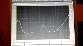
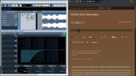
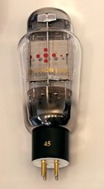
It is very fast, and in my amps using the low mu 6AS7 it swings +-120volts at over 50kHz with no problems, even with several in parallel. For driving an output tube's grid it also is beneficial that the current is at it's max when the output swings up. (Noninverting).

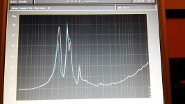
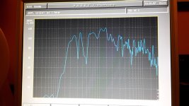
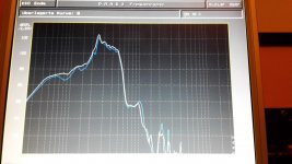
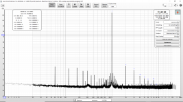
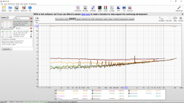
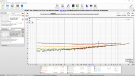
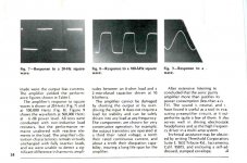
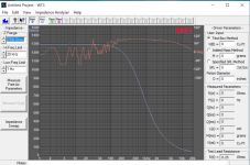
I have tested various mirror types, wilson mirrors, cascoded outputs, MOSFETs, BJTs, etc. The spectrum analyzer shows near identical performance with all, making me believe the tube is the dominant contributor, so I consider this a hybrid circuit with tube dominance. (And I use the simplest mirrors).

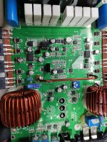
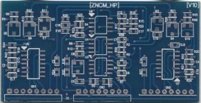
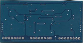
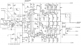
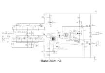
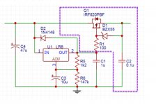
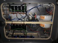
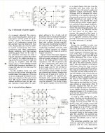
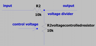
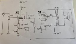
Anyway, before going too far, here are some sample circuits I have built using this topology.

These are simplified schematics, but show how direct the signal path is. I do not bother draw in the grid stoppers or the various power supply components. (The excellent article by Lynn Olson about current loops is a must read when optimizing the supply).

Btw. I found this thread about mirrors which I havent had time to look at yet, but hopefully it is an interesting read. Perhaps tonight with some good wine and and a few good records🙂
http://www.diyaudio.com/forums/solid-state/133018-current-mirror-discussion.html

how can I display the difference between 2 pots ?

Good morning!

I'm in brain-cooking mode, trying to figure out how I could display the difference between 2 potentiometers (like, volume left to volume right).
It would be for a balance- or volume-indicator of two independent knobs (with a "master" volume-pot being present), so it would be interesting to see the difference of those two...

Like:
L is -6, R is -6 = 0
L is 0, R is -6 = -6
L is -6, R is 0 = +6

I was able to come up with a mechanical possibility (think gears + springs), but it would be interesting to see if others have come up with other methods? How would this be done the electronic way?

Have a nice day
david

6mm to 6.35mm pot knob adapters

Just came across these little adapter sleeves thought I'd pass it along as a construction tip. (I have no affiliation with the seller). I'm usually in the tubes forum. These allow you to fit 6.35mm knobs onto 6mm pots or rotary switches. If you've ever put a 1/4 inch knob onto a 6mm shaft you soon lean that the knob rotates "crooked", because it goes off center even though the grub screw is holding it tight, it is pushed off center. And it looks and feels like crap. Also there are many, many more 1/4 inch knobs to choose from in the vast knob marketplace than 6mm knobs. Most 6mm knobs are ugly Chinese crap. Swap meets, ham-fests, flea markets, etc. are just full of people selling great looking bakelite 1/4 inch knobs. And old companies like Davies Molding are still making those great looking ham radio 1/4 inch knobs from 1930's molds!

I'm going to order a bag of these now, they seem to be just what I needed. Thought it might help others solve this problem. Also I've tried building up 6mm knobs using aluminum tape, that is also a disaster as the tape compresses, knobs loosen and you cant get the exact diameter, and the knob is still off center.

Brass Pot Adapters – 6mm to 6.35mm (x20) – Thonk – DIY Synthesizer Kits & Components

audibly transparent dust filter material?

I got some dust electrostatically stuck onto my planar diaphrams and it has caused some resonances that cannot be removed without cleaning.

I am trying to find some material that I can use to cover the diaphram without affecting the sound. I've tried a few foams and synthetic cottons which have audible transparency but they take the edge off of the bass.

Also the synthetic cotton just got micro fibers all over the diaphram adding to the dust issue.

Does anyone know a good material I can use for this purpose?
Appreciated.

For sale: EML 45B tubes (pair, satisfaction guaranteed)

Hi - I am selling my near new pair of EML 45B tubes. These are the 45B (not 45) which have higher output, can handle higher voltage and plate dissipation. Tubes have about 350-400 hours. Looking for a friendly home. If you don't like the tubes, you can return in working order within 7 days for full refund, less shipping.

Contact me directly at banpuku@mac.com
Thanks, Pat

SOLD!!!

Attachments

  • 45B-Small.jpg
    45B-Small.jpg
    34.4 KB · Views: 169
  • download.jpg
    download.jpg
    4.1 KB · Views: 159

Basic Advice On Live Sound

Hi,

I am struggling to get my head round working out how much watts I am sending to my speakers as unfortunately last week my daughters band managed to damage there speakers during a live gig.

The currently only use the PA for vocals and the rest of the band use there own guitar amps.

the setup they have is:

Shure SM58 Plugged into a Mackie CFX12 (Mixer) in turn connected to A Samson s2000 AMP which in turn was connected to 2 x Studiomaster GX15 passive speakers (Until the started smoking and are now broken or at least the crossover board and tweeters are, the bass cone seems ok in both).


We usually set the mixer to Unity on the mic channel and also Unity on the master output.

We set the gain so that it only flashes when the vocalist is doing her loud parts.

Once this is set we usually turn the AMP up till we get the vocals coming out the speakers and being able to be heard above the rest of the band.

And this is where we feel we go wrong and end up blowing speakers. The amp has 2 dials on the front where fully counter clockwise it reads -80db and fully clockwise 0db we usually end up setting it around between -10db and 0db. The speakers are rated at 250W (continuous), 1000W (peak).

I feel we are doing wrong but just not sure how.

Again please bear with me as I am an amateur in this game.

Many thanks for your time.

Choice of dual transistor for input stage, how much current ?

Which dual npn transistor would be the best choice for differential input stage ?

I have a set of MAT02 already but need more and those are hard to find.
If buy from chinese seller, will metal cans probably be fake ?

What parameters are most important ? Hfe, hfe matching, ft, Vbe match ?

2N2920 has only 60 MHz, would that be enough ?

How much current is to much ? At 6mA per leg and with heatsink there is no problem. Hfe goes up with current, right ?

DC heaters - leave floating or elevate?

I've been struggling with hum in my new preamp. I assumed it was a ground loop, but it's actually being caused by the heaters. They are DC fed with the 0 volt side tied to the star ground. If i disconnect that from the star ground and leave them floating, 90% of the hum goes away and I only hear it when the volume is much higher than I ever listen. Does it make sense to keep it floating like that? Or should I try elevating the ground? The circuit is the cornet octal: http://www.hagtech.com/pdf/cornetoctal.pdf

How to guess the value of this filtering inductance?

Hello! I am in the process of reverse engineering a Klipsch ProMedia Bluetooth 2.1 computer speaker system.

To expose some tracks on the control pod PCB, I had to remove a blob of epoxy glue. While removing the glue I also removed what I think was an inductor under the glue.

Eventually, I was able to reverse engineer the circuit and now I would like to replace the inductor. However, I have no idea what kind of inductor to purchase.

As you can see from the photos the inductor is very small and is damaged, so little hope to measure the inductance directly.

My questions are: what is the purpose of the L1 inductor? By looking at the schematics can you guess what is the original value of the inductance L1?

The inductance dimensions are about 3mm x 1.5mm x 1.5mm.
The LEFT_IN and RIGHT_IN signals come directly from the jack input. The WIRED_LEFT and WIRED_RIGHT signals go on to the input of an OPAMP amplifier.

Here are part of the schematics and some photos of the inductor before and after the glue removal. If you need further info please let me know.

dK-JLaZA.png

inductor.jpg

Inkedafter-glue-removal-LI.jpg

Inkedbefore-glue-removal-LI.jpg

Kenwood KAC-9106D

This amp came in with blown PS and outputs. Insulated STP60NF06FP in the PS. Gate resistors are 68 ohm 0603. Pulldowns are 4.7k. Drivers are MLZ transistors from a TL494.

Was wondering if IRFIZ48GPBF would be suitable to STP60NF06FP since those are not in stock anywhere. Need the be encased. Has anyone tried these or other combination? I also need to replace the 68 ohm gate resistors. Maybe go to about 33 ohm?

Outputs are IRFP250N pairs on each side, one of them blown on each side.

I clipped all bad parts and put two IRFZ44 temporarily in place in the PS. Amp is working.

Subwoofer-shake cancellation theory...

I know a lot of people use dual subwoofers in an opposed assembly to cancel out vibrations. Since some high-Xmax drivers get very pricey very quickly, is it possible that using some active bass shakers as an opposing oscillating mass would be a more cost effective method of cutting down on the subwoofer-shake syndrome?

Most of the time, the cabinets are heavy enough to keep the subwoofer in check, but with the new breed of long-throw high-mass power-hungry mongrels, the boxes really don't have to be very big or stout to accomplish the performance goals- unless you want it to sit still as well.

Here's the theory as to why this would work. Bass-shakers utilize a backwards assembly vs the standard/typical subwoofer driver. The shaker uses a fixed coil and an oscillating mass. Typically a shaker will likely have a higher mass to velocity ratio than the subwoofer. I figure if keeping the motion opposed in subwoofer vs shaker, the active cancellation will actually reduce the vibration of the cabinet in relation to the room and its relative position.

Please- discuss this! I'm looking for any reasonable thoughts on this matter.
Thanks,
Wolf

why most hifi amplifiers use a large dropping resistor just before the 1st stage

Hello. I am trying to build a hifi amp from scratch, and when I studied the tube hifi schematics, I found most, if not all, use a large dropping resistor (B+) right before the 1st input gainstage. The values are about 47k to 68k, while closer to the transformer it is more between 4k to 10k.


Thank you.

First build and doing things backwards.

Hi,

Apologies in advance for coming at this the wrong way. I have a box, I do not yet have a driver. Basically I want to build a streamer into a nice box I found. So immediately we are not talking hi-fi here. But the box is pretty solid and I would like to get a decent sound out of it.

So can you good folks suggest a full-range driver that would work in a box of a little over 4 litres internal volume?

The internal dimensions are D 87mm x W 189mm x H 263mm. Yes, that's right, it is shallow (actually an attractive and solidly built presentation box for two bottles of wine!).

Considerations:

  • Cost: Looking to spend a few 10s of £s - I'm in the UK.
  • Wide dispersion to fill the room as much as possible.
  • Bedroom listening environment - low volume classical and spoken word mostly.
  • Ported or sealed configuration.
  • Shallow space - maybe two smaller drivers wired parallel would fit better. How nasty will this make the off-axis response?
  • First thought was that I'm looking at a mono design, I guess there would be nasty intermod running stereo. But how about two drivers, driven in (software) mono by a stereo amp? A stereo dac+amp board is easier to source.
Thanks in advance

Tom

Dayton WT3 under Windows 10?

Has anyone been able to get the old WT3 tester to work correctly running on Windows 10? I have tried everything I can think of with no luck. I've tried all the things describes in this post:
Faulty Dayton WT3... and more.

Compatibility modes:
  • WinXP
  • Vista (different service packs)
  • Win7
  • Win8
All different versions of the WT3 software available.
Mic levels from 1 to 100 (40-50 seems best)
All enhancements off in Windows and Realtek controls.

The software (all versions) does run and will open old files, but new sweeps and calibration don't work. The best I can get is the plot seen below.
The hardware seems to work, it can send and receive audio in other software and measures flat in HOLMimpulse and ARTA. I have two of the devices, both show identical results. It's impossible to calibrate the leads, the software returns and error saying that the lead resistance is too high. Default calibrations don't do any better.

Is there some setting in Win10 that's I'm missing? The last time this functioned properly was under Win7. Since using win10 the results are obviously bad.

Attachments

  • WT3.png
    WT3.png
    43.1 KB · Views: 273

How do I figure out the Compression Ratio from Voltage Divider

I am building an audio compressor and I am using a voltage divider. If I lower the voltage of the voltage controlled resistor as shown in the schematic, the voltage is cut in half and this is a 6db loss of voltage. How do you figure out what the compression ratio is? is this 2:1, 6:1 etc as shown?

Attachments

  • Capture.PNG
    Capture.PNG
    27.1 KB · Views: 247

42SE amp idea

So this is my idea for a 42 SE amp with a 75 driver. I have a couple of 76 tubes that could work as drivers too, but decided on the 75 driver since the extra gain could come in handy for feedback application. There are a couple of issues still, so any suggestions are much appreciated.

- The feedback circuit isn't calculated as much as borrowed (all right, stolen) from an amp with a 6V6 and a vaguely similar driver tube, so I'm not sure if this will work at all. Is plate to plate feedback an option?

- Is UL operation a good idea at all with the 42? I could run it in triode if I can get by with less than a watt, and a screen supply for pentode mode isn't much work or parts.

- My drawing doesn't have grid stoppers, but I will use them.

Attachments

  • 42se-amp.jpg
    42se-amp.jpg
    35.1 KB · Views: 257

UK suppliers of rubber for under transformer

Hi everyone, I'm looking to replace and upgrade some rubber (or foam?) under toroidal transformers in some amps. It's not something I've done before, and I'm struggling to know what the best stuff is to get and where to get it from (in the UK). Any pointers?

I'd like to buy decent-quality stuff, but the likes of sorbothane is far too expensive. 2mm would be ideal.

Thanks.

FS: Tested NOS 6N6P / ECC99 / E182CC Tubes Novosibirsk 1984

The indicated twin triodes tubes from a sealed big box, I ask 5usd per 1pcs.
All tubes have been roughly tested at 0V grids bias, at least plate currents of the halfs can be compared and corresponding tubes selected.
Cost of the air post to USA is 8 usd if up to 0,25kg parcel weight, 14usd if up to 0,5kg, 24usd if up to 1kg. Please ask if there are some more questions.

Help to identify Amp

Hoping someone can identify an amp I have. It is obviously a guitar/band amp that has 4 EL34 output tubes and the letters LP on the front panel. I cannot find any reference to LP amps and don't think it is Les Paul but you never know. Images attached this time.

Attachments

  • IMG_0806.jpg
    IMG_0806.jpg
    308.9 KB · Views: 227
  • IMG_0805.jpg
    IMG_0805.jpg
    285.7 KB · Views: 219
  • IMG_0807.jpg
    IMG_0807.jpg
    294.4 KB · Views: 230
  • IMG_0808.jpg
    IMG_0808.jpg
    495.3 KB · Views: 222
  • IMG_0809.jpg
    IMG_0809.jpg
    525.8 KB · Views: 225

Questions about connection quality

First I want to state that I'm only concerned about electrical connection quality, for the sake of this argument assume mechanical connection quality is irrelevant.

I have read that a soldered connection is always best (which makes sense). But what is less clear to me is how much *worse* other types of connections are. For example, friction-based "quick disconnect" tabs, or screw-down terminals.

For that matter, how much does an extra solder joint affect the connection? How different is a single cable vs. two cables soldered together?

Or, lets say you have an IC with a broken leg. You solder a new leg on as a patch. Have you quantifiably degraded the performance of the circuit?

Help with parallel notch filter

Getting some conflicting information from various online calculators. I have a simple peak I'm looking to tame at 630 Hz. It is 6dB strong, and about 3dB strong on either side at 500Hz and 800Hz respectively. Beyond that it is basically flat.

I'd love to come up with some consistant inductor, capacitor and resistor values as a starting point. Can anyone help?

Thanks 🙂

TDL Studio 3 crossover upgrade is better and yet worse as well

Hiya,

I've just replaced all of the components in my TDL Studio 3s crossover.

I've gone for point to point soldering on the components without a pcb or board of any sort.

I've used the following components.

3.9uF 800Vdc Jantzen Superior Z-Cap (ON THE TREBLE)
10R Jantzen Superes 10W Resistor
2R2 Jantzen Superes 10W Resistor (2.2R)
12uF 450V Mundorf Mcap EVO Capacitor (ON THE BASS)

I've also got new inductors of the same value as the originals done by Gerry at Falcon who knows TDL speakers well.

The improvements in the treble is night and day. Much cleaner, more space better soundstage. The bass seems a tiny bit flabbier (not much in it though) but it's the midrange that seems to be worse. Not terrible but noticeably more muffled than before.

I've still got the original Xover in tact but before I start mixing an matching I thought I'd see what you all think could be the reason.

I'm letting them burn in/ run in to see if that makes a difference (I'm not trying to start a chat about that well trodden and controversial issue so let's pretend I never said it...just trying to eliminate all the possibilities!)

The only differences with the original values is the high pass cap which is a 3.9 rather than the original 4. I've also extended the wires a little as they were quite short and needed extra room to work. No more than 6cm with some decent van damme cable I had. I've used solder with a bit of silver in it and they have been running for a day or 2. Oh and the resistors are 10w instead of 5 but I don't believe that should make and difference.

Can anyone suggest why the midrange seems to have got worse?

Thanks

NAIM NAP120 "Recap"

I am being threatened with a Naim NAP120 for a "recap" job. The distributor does a kit of parts for this at quite a high price. Is there anything in there that cannot be sourced from all the regular (RS/E14/Digikey/Mouser) suppliers with whom I regularly do business?. I have not yet laid eyeballs on this beast so uncertain what is involved (big reservoirs only? a zillion tiny tantalums?). Anyone been there & done that?.
M

Help potentiometer Burson Soloist ha160

Hello good community, I am in a problem, since the stepped potentiometer that comes from stock in my Burson Soloist ha-160 died and I have to change it, the truth is I do not know what type of potentiometer I should put on it, I tried to contact the manufacturer and they told me that no longer have a spare. I have read that it is possible to put an ALPS Blue but the truth is I have no idea, the Burson comes with a cable to connect 3 pins to it, I will upload photos so that you can guide me, I would greatly appreciate them and also what recommendation would you give me.

Attachments

  • WhatsApp Image 2021-06-15 at 14.22.40.jpeg
    WhatsApp Image 2021-06-15 at 14.22.40.jpeg
    85.4 KB · Views: 225
  • WhatsApp Image 2021-06-15 at 14.22.14.jpeg
    WhatsApp Image 2021-06-15 at 14.22.14.jpeg
    75.3 KB · Views: 230

Class D vs speaker impedance

What determines whether a Class D can withstand playing in 4, 2 or 1 ohm?
The output filter will of course differently frequency rolloff and the coil in the output filter must be able to carry the current.
However, when the FETs "only" switch on and off, they can probably not be compared with, for example, a bipolar transistor in a class A / B amplifier ?

If a class D amplifier uses a pair of IRFB23n20d, does that say anything about how low impedance the amplifier can be loaded with?

The powersupply to the amp are 2 x 44 Vac (2 x 62 Vdc)

http://www.irf.com/product-info/datasheets/data/irfb23n20d.pdf
Projects by fanatics, for fanatics
Get answers and advice for everyone wanting to learn the art of audio.
Join the Community
507,758
Members
7,887,202
Messages

Filter

Forum Statistics

Threads
406,170
Messages
7,887,202
Members
507,758
Latest member
Cindy