Myryad MC100 CD squeak

I've owned my MC100 since new (IIRC about 1998) and it's been sat a while between uses (typically for parties with loud music) but now I'm using it with headphones about 1 foot away from the sitting position.
On playing a CD it has developed an annoying auditable squeak.

From my understand it uses a Sony CD engine so I suspect the transport is similar to many other CD players.

Before I get the screw drivers out to clean and lube - is this a DIY easy operation or am I going to destroy any alignment?

FS: Sowter 15W P-P output transformers for EL84, Baby Huey

I ordered these last year but am changing direction with some of my projects so putting them up for sale.

These are Sowter push-pull transformers, size I.
"15W at 30 Hz. The LF response will still be -3 dB at 20 Hz or better."

Primary is 8k
Secondary is standard Sowter with 4 individual taps that can be winded as 4, 8 or 16 ohms.
Screens are tapped at 25%, perfect for a UL EL84 amp such as the Baby Huey.

One transformer is still wrapped. The primary wires were cut on the second, but there is still 9 inches left so more than enough for any chassis configuration.

These would cost around $680 if purchased today, and would take 4-6 months to arrive.

I am asking $640, including shipping and fees.
Price is relatively firm as these are hard to get and I'd rather keep for a future project than lose a ton of money on them.

Attachments

  • 2021-09-07 10.00.40.jpg
    2021-09-07 10.00.40.jpg
    304.3 KB · Views: 291
  • 2021-09-07 10.00.26.jpg
    2021-09-07 10.00.26.jpg
    404.2 KB · Views: 295
  • 2021-09-07 10.00.23.jpg
    2021-09-07 10.00.23.jpg
    337.7 KB · Views: 281

2 way project improvement?

Hi all
5 years ago I realixed my first speakers project.
I used SB17NRXC35-8 woofer and SB26STC-C000-4 twiter. Below all details about saled box and crossover filetrs.

Aldought it was my first project I have to say that the result was very good and during these years I enjoyed a lot of music 😀

Now I was thinking to re-design the box to use a port vented one. This because I would lime to improve the low level frequencies response.
Do you think that it is a good idea? Do you have suggestions?

Attachments

  • XO.jpg
    XO.jpg
    3.2 KB · Views: 376
  • SPL.jpg
    SPL.jpg
    3.6 KB · Views: 377
  • impedence.jpg
    impedence.jpg
    147 KB · Views: 345
  • woofer_diffraction.png
    woofer_diffraction.png
    47.6 KB · Views: 346
  • boxycad.png
    boxycad.png
    36.1 KB · Views: 371

Fender Passport & External Mixer

Hello everyone,

I am new to PA system and would appreciate if the experts here could help identify an issue I am having with Fender Passport.

Issue: If I turn the volume of the Fender Passport pass mid level, then the mics (connected to external mixer) get distorted.

My equipment:
Fender Passport Deluxe PD-250 (current setup) - 250W
Fender Passport Venue Serie 1 (future setup) - 600W
Mackie Profx8 8-channel mixer
2 Sennheiser E945 Dynamic mics

My setup:
2 mics connected to 2 channels on the Mackie mixer.
XLR cable out from either a Left or Right output on the back of the mixer and connected to input channel 1 on the Fender Passport.
Instruments connected to other inputs on the Fender Passport.
OR Playback music devices (TV or Phone) connected to Stereo input on the Fender Passport.

Issue:
This setup works perfectly in a small enclosed area like home or garage since the I normally keep the volume less than 50% on the Fender Passport. However, if I have to crank the volume pass 50%, then ONLY the mics (vocal) get distorted or breaking. Instruments and stereo playback, etc which are connected directly to the Fender Passport are fine.

A few notes:
The reason I want to have the mics go through the Mackie mixer first is because I found that the FX Presets on this mixer work perfectly for the vocal I need, especially the FX Preset #16 REVERB + DLY (250ms). I don't know the technical on why, but it just sounds perfect for me and everyone I know. Connecting the mics directly to the Fender Passport PD-250 does not produce a good vocal.

Questions:
1. Is there anything wrong using an external mixer to connected to a PA system like that?
2. I am buying a Fender Passport Event which is much bigger speakers and more power, would that solve the issue?
3. What would you recommend to improve this setup to eliminate this issue?

Thank you very much in advance.

Systemdek 11x 900-External power supply options?

Hi,
I have a Systemdek 11X 900 with a standard mains power supply to the motor. I'd like to fit an external electronic power supply that maybe filters or stabilizes the mains supply voltage and maybe allows speed switching. What are my DIY options? Thanks.


PS Maybe I could upgrade the motor as well as it uses a standard 110v AC one. Could I fit a DC motor instead? Maybe a Linn Valhalla board? Or a Project Speedbox?

iPhone SE question

So I get a call I don't pick up in time. Later I look and see the facetime icon beside the number that called. I call back because they did not leave a voice mail. When I click on the number, my camera turns on and takes my picture, however that's where the call ends. I did this repeatedly but now with my finger covering the lens. My question is, did that caller receive my pic? Is this how a facetime call works? You can just sneakily get a pic of someone that way?

Marantz 7C tone amp design related to Baxandall?

While building a replica of a Marantz 7C and now working on the last phase of the build (tone amp), I became interested in what type of tone control circuit was utilized and if Saul Marantz and engineers he was associated with in the 50's were already knowledgeable in tone control (within feedback loop) design or if they would not have had the necessary technical expertise without the work of Baxandall. Or, is there anything in the 7C tone amp design that could even be remotely related to Baxandall's designs?

I had the pleasure of reading the thread by JoeAlders (Bass-Treble potentiometers in Baxandall tone control) and it peaked my interest in the subject matter even more.

Looking forward to any feedback on this interesting subject.

I'm attaching a snip of the Marantz 7C original circuit for reference.

Attachments

  • Tone stack 7C.PNG
    Tone stack 7C.PNG
    576.5 KB · Views: 344

A try to build a studio monitor-like speaker

I know this has been discussed to death, and the goal to build i a real full neutral studio monitor is a very high goal. But as i'm looking for something to make my radio broadcasts and amateur music mixing a bit better, i was looking arround in the studio monitor market and heared a lot of very bad cheap monitors. Good monitors exist off course but they all kost an arm and a leg. But the ones i can afford (<1K) are less revealing and translating well than my Mark Audio Alpair 10.3 reflex i use now so not worth the investment.

So i thought i may do better by try to build something myself than those cheaper ones i can afford. And even if i fail, the journey to get there will learn me a lot. I did build quiet a few not so neutral but good sounding fullrange speakers (at least to my opinion) and did study the subject for years. I did hear some very good kits like the Tango MT (owned by a friend) that are more like what i try to reach. I'm also inspired by that one, but as that tweeter is unavaileble, i had to change the plan. And no, i don't want to build a kit, the designing is half the fun and learns me something, kit's don't do that anymore.

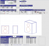
I'm going to keep that Dayton RS180-4 driver and pair it with the exellent SB26ADC tweeter in a 2 way reflex. A waveguide could give it a broader and flatter dispertion, but i don't need that as i'm mixing in the box and i'm always at the same spot (in my chair on my desk). So i need a speaker that is relative flat on axis an go low enough to fit most music without a sub. Adding a waveguide would complicate this build for me a lot as i don't have the tools nor the skills to make one.

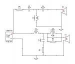
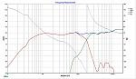
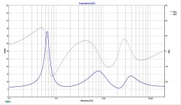
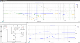
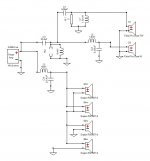
The plan i made is a 30L reflex tuned to 32Hz F3 wit a front slot port. It will be build in 18mm birch plywood. Crossover will be passive for the moment as good dsp chips and so are out of stock or way to expensive at the moment. I may convert it to active later on when that issue is resolved. The crossover in the plan is a starting point, calculated and simmed with regards to the alignment of the drivers and the offset of the woofer and so but based on published graphs. I'm going to measure off course when the cabinet is build and the drivers are mounted and adjust the crossover (but i needed a starting point and a check if the drivers can meet). BSC is not included as the speakers will be against a stone wall (which is not perfect, but that is what i have to deal with) that will make up for that largely. I will line the cabinet with felt and maybe even damp it with bitumen sheets (i got some leftovers from other builds in stock).

But before i start, it's maybe time for a reality check on obvious mistakes i made within this goal. Full plan is in the pdf attached like i would make for a publishing (which i will when it's finished). So shoot...

And for those who maybe want to build it, you can (as long as it's not a commercial thing) but at your own risk, it's not verified in reality. This is a first draw.

Attachments

Revox B261 Tuner-Audio board stability/Improvements.

I am currently recapping (electrolytic only to start with) my Revox B261 FM tuner. I have completed the power supply, the MCU board, the audio board (schematic and PCB layout attached) and the stereo decoder board. Next is the demodulator (1 cap only). I will do the rest gradually.
I have some annoying instability on the headphone output (other variable output sounds fine). There is distortion that seems to be triggered by the output relay connecting the headphones (I'm using Grado SR80 and Sennheiser PX100). It also seems to settle when warming up. When I place my fingers under the PCB and brush them over the traces/joints the distortion will suddenly reduce and the sound suddenly improves (after lots of hum and the occasional whistle). I have checked the following
1/ All resistor values OK
2/ All ceramic caps OK. All electrolytic capacitors replaced (most of them have tested bad on a BK Precision 879B LCR meter).
3/ PN junctions of the transistors check out OK.
4/ Continuity checks done and solder joints reflowed.

I have NOT checked the components on the headphone PCB yet. That is my next job.

I'm just wondering if replacing the LM301 op amps would yield some improvement in performance and stability (OPA132 or NE5534A). I don't want to replace the ceramic caps unless needed to aid stability.
I've not injected any signals into the board or looked at the output on my scope yet, so maybe I should try this next. Any suggestions for any other next steps? Thanks.

Attachments

Tube Amp Output Questions ?

I have a small tube amplifier from China. It is 6 wpc Single Ended Class A with both 4 and 8 ohm taps for the speakers. The Taps are not marked 4 or 8 ohms and the company that sold it to me is out of business, and in China!
Is there any way to tell what Tap is the 4 ohm, and what Tap is for 8 ohms ?
I do not have a schematic of this amplifier, and doubt I can get one.

Minx X201 General Input Question

Hello,

I am planning to use a Minx X201 from Cambridge Audio as my subwoofer but I have a interrogation (which is quite general to active sub I think).

Here is the backplate inputs :


If my understanding is correct, for a 5.1 system I use the LFE output from amp and go to L (LFE) on the sub. And for a stereo system, I can directly feed the L/R analog input and the sub will made a low pass filter on it according the cross frequency knob.

Now my question :

If I leave plug in L/R cable constantly and that inside my DIY amp I use a analog relay to switch between only sending LFE signal (.1) on the L input or stereo signal on the L/R. Will the sub be "smart" enough to detect when there is signal on both input and when there is only LFE signal on L ?

I hope my question is understandable 🙂

Thank you.

Open Baffle 2x15" at different LF XO frequencies

Hello,

Apologies if this is too simple or has been asked before, I did look but could not find. Is there a way to set up 2 drivers so that:

One rolls LF off naturally, the other has HP filter set so that the net result of both drivers together is greater LF extension (combined higher amplitude at lower frequency) than if both drivers were simply connected in parallel.

Is this credible, and if so, is it used commonly?

Thanks
Isaac.

Easy way to waterproof outdoor speakers?

I have a newly built outdoor music listening station at my BBQ, and it's in the elements. I usually just swap the speakers with new thriftshop speakers every year or so, but I'm wondering if there's something as easy as a bag or something I can put over them?

When I put a regular garbage over them I lose a bit of the treble, and they sound so good that it's painful to lose that little bit. I'm wondering if there's something acoustically transparent that anyone knows about that will protect speakers from the rain?

Or some other clever idea?

AM-JKLXSzKFBb_R1gFTsYdSB_anMhd_za4RCdOuAw7BpOHUNx8p2ARKo_oFZSNUxanxnZMzDR9HX7v6xNFU7LF5d0FyDOrA0j_JpSoAjvQLcPCb4oazFKXpdPXFCCtdQhhR4XA7f5lZkbvvKfh3eHp_eQrkghw=w1112-h943-no

Grounding suggestion

Hello there,
I am building my first point-to-point amp (a Bugle 45 by G. Rankin, with some mods suggested by him). I decided to use a dual-panel chassis with a wooden frame separating the power supply section from the signal one, and two heavy (1/8") aluminum panels.

I built a ground bus for each section with 10 AWG bare wire. All components that should go to ground are connected to it. See picture (note that I haven't received my power and filament transformers yet so some connections are missing, but you get the idea. I also added a wire from the mains earth to the PSU ground bus). The chassis is not connected to the ground yet.

Does my wiring make sense so far? I am not sure what the best way to connect the two buses and the chassis would be. Shall I run another piece of 10 AWG wire between the two buses, making an "H", and connect the two chassis panels to the closest point in the bus? Does the connection point or the wire gauge make a difference?

I'd appreciate any help. Thanks.
gm

Attachments

  • IMG_20210405_164257.jpg
    IMG_20210405_164257.jpg
    994.4 KB · Views: 238

Tannoy 15” concentrics

I have decided to give these larger Tannoys a try. I would like to ask for advice for specific driver models, version to look for. Trying to Stay away from the vintage ones that fetch crazy prices.

I have auditioned CPA15’s and those sounded good. Do they use some of the better tannoy 15 drivers? What driver model to hunt down?

Will be using subwoofers.

I know ZM and possibly others members on this forum could provide some insight?
Thanks

Digital Bit Rate Converter

I have a bit of a rare beast, it converts 24bit 96kHz TOSLINK to USB, so you can feed optical audio data straight into a USB port. Hifime SPDIF Optical to USB converter, record DAT/minidisk to computer

The unit works with a maximum of 24bit 96kHz, if the unit receives a higher bit rate you get distortion and background noise.

What I am looking for is something that has optical input and output that will reduce streams of up to 24bit 192kHz data down to 24bit 96kHz.

I suspect that such an object is even more rare than my optical to USB converter.

why do these iSEMcon microphones go through a distortion minimum at 120 dB SPL?

All three mics tested in these two reviews show 2nd harmonic that falls with SPL down to 100 dB where the noise specified at about 31 dB takes over. This makes perfect sense qualitatively, even if I'm still struggling to understand it quantitatively. How can it match the noise spec almost perfectly when the analyzer will only allow a tiny slice of the spectrum at 2 kHz +/- a few Hz?

However, the 3rd harmonic goes through a minimum of about -90 dB at 120 dB and then goes up again as SPL falls further, rising about 10 dB for every 10 dB drop in SPL. This does not look noise-related, as the rise begins at much higher SPL than for the 2nd harmonic.

https://www.isemcon.com/datasheets/iSEMcon EMX-7150.pdf
https://www.isemcon.com/datasheets/iSEMcon EMM-13D082.pdf

What is going on here? What nonlinearity mechanism is there (other than noise) that actually increases as the signal goes down? Mechanical hysteresis in the membrane? Sinister storage effects in the electret? Or is there a more mundane explanation?

Attachments

  • EMX-7150 disto.PNG
    EMX-7150 disto.PNG
    139.8 KB · Views: 187

ARRRRRRG!

Set up to track down a couple resonances in my room. Off frequencies. 538 and 302. Plus I have more 60 Hz and harmonics than last time I was set up.

It's my Focusrite 2i2! Right channel is bad. Left still OK. I can't imagine what happened to it.

Guess I need to decide if I get another, or go for a USB DAC. I actually have one, an Anthem, but their cal file is encrypted and they won't share it. It looks not too far off. I might be able to do a nearfield sweep and compare it to my ECM 8000 on the good channel and hack a file close enough.

How Audible is XO Inductor Crosstalk?

Hi Folks,
This is something we see and think about when designing and building crossovers. We try to separate inductors as far apart as possible and we align them so their B fields are perpendicular. But have you wondered how effective this is and just how much of an effect it is?

Well I found out by accident when I was testing two identical crossovers for my FAST TL’s. I had one connected to the speaker drivers and no amp. I had another one connected to an amp (playing music) and no speakers. To my surprise, I heard quite audible music being played! The boards were about a foot apart. I suspected it was vibrations in the crossover that made noise at first (caps or inductors can mechanically vibrate). But I was not playing that much signal. I finally realized it depended on the separation distance of the boards and that the sound d was not from the XO board but from the speaker which was right next to it. So I moved the XO board around and checked orientation etc. it helps to cross the axis perpendicularly, but doesn’t eliminate it.

Something to keep in mind when laying out your coils on your crossovers.

Here is a video of what I saw:

Demonstration of Inductor Crosstalk in a Crossover - YouTube

The crossovers I was testing for basic functionality before packing them up to ship to my cabinet builder:
997002d1636703789-bench-tonight-obt-4057e842-b548-4b6c-b7a7-19afd60f7ddd-jpg


If you guys have similar stories or experiences I would love to hear them. I wonder how much worse iron core ones are? I think worse if laid side to side or end on end.

ADS AB 1000.1DB mono burned series resistor

Good day bro , i am troubleshooting an ADS 1000DB mono amp, Chinese made amp that suddenly smoked , i found out that the 2 resistors as shown R32 and R33 got burned . R32 came in series from +D3 and goes directly to Pin 1(Vin)of KA7815 while R33 came in series from-D1 and goes directly to Pin 2(Vin) of KA7915. The regulators are Vsupply to TL0804. The diodes D3 and D1 other end connects directly to the transformer. Can you please help me of the values of the 2 resistors? they are totally burned & identifying the color codes is not possible. Thank you in advance.

Attachments

  • ADS 15v supply 1.jpg
    ADS 15v supply 1.jpg
    101 KB · Views: 112
  • ADS 1000 Amp.jpg
    ADS 1000 Amp.jpg
    129.6 KB · Views: 131

Working with available data - discussion.

I like F1. I recall the battles at McLaren between Lewis Hamilton and Jenson Button. The difference between the drivers (excuse the pun) is that Button needed a perfect set-up to perform but Hamilton could achieve good results, wringing performance out of a less than ideal set-up by driving it like he stole it.

This scenario leads me to question the data that the 'Airfix posse' base their decisions on. We are informed that the Acme 12x Turbo is a world-beater but requires 90 litres to fully flex its muscles. Subscribers will discard the option based on the volume requirement. But there is no data informing the customer a 50% reduction in cabinet volume decreases performance by only 3% - still ahead of the competition.

Maybe my observations are both subjective and anecdotal but I've experienced drivers that will do their job to the best of their ability in the environment provided and other, prima donas who will down tools if their every desire is not met.

Muse Electronics Model 3 Balance Preamplifier

Muse Electronics Model 3 Balanced Preamplifier

Muse Electronics Model Three Balanced Preamp. Condition is "Used".

Excellent sounding Balanced preamp from Muse Electronics. Three Unbalanced inputs and two Balanced inputs. Works great.

An after market programmable Remote included (Chunghop RM-L7), but only has Mute, Input 1, Input 4, Input5, Power, and Volume Up working.

I noticed that my Logitech Harmony Remote settings for two different manufacturer remote codes worked for different settings on the Model Three. I managed to get all these codes into a Chunghop RM-L7 Universal remote. Just never found the Volume Down equivalent...

Volume up - Volume up
Mute - Mute
Ch Up - Input 1 (Unbalanced in)
Ch Down - Input 5 (Balanced in)
A/V - Input 4 (Balanced in)
Power - Power (will only power down when unit is in Mute)

To power on, click any input.

No longer using it...so up she goes...asking $550 + ship from Sub of Chicago

Attachments

  • s-l1600.jpg
    s-l1600.jpg
    131.1 KB · Views: 557
  • s-l1600 (1).jpg
    s-l1600 (1).jpg
    128.4 KB · Views: 597
  • s-l1600 (3).jpg
    s-l1600 (3).jpg
    213.1 KB · Views: 584
  • s-l1600 (2).jpg
    s-l1600 (2).jpg
    155.9 KB · Views: 575

Help choosing 8-9 inch Al woofer

Coming out from my last project 7+4+1,which sounds pretty good, but not amazing. Although I've played with the passive x/o for almost 3 years and I got relatively flat response (+/- 3dB), I've never got the same coherent sound like my headphones. I suppose the different cone materials sound quite different way - the polypropylene midbass is punchy and dynamic, the paper mids are soft and delicate and the dome highs aren't sufficient in the top range over 10kHz. As a result the brass instruments and the cymbals sound quite unconvincing.
BTW I would like to try something with metal cone drivers. For more simplicity, I'll try some WAW with SB65WBAC25 without tweeter, crossed within 400 - 500Hz range, where is the baffle step frequency. The SPL over 1kHz is about 85dB, so I'll need some 8-9 inch, 4 ohm Al cone woofer with sensitivity 89 - 90dB (with serial inductor it drops to 88dB and 3 - 4dB for the baffle step).
My first choice was SB23NACS45-4 - pretty good on paper. Fitted in 45l ported box seems it has capability to reach f3 of 37Hz and f10 of 22Hz. Unfortunately it's not available in UK, but it's in stock in Soundimport NL.
Do you have any other suggestions?
Thank you in advance
Regards
  • Like
Reactions: tamra

Marantz 7C build tone rotary switch

I want to duplicate the Marantz 7C tone stacks in my 7C replica build. I purchased what I thought would work for the bass tone rotary switch based on my interpretation of the schematic but in looking at photos of a disassembled 7C bass rotary switch and the level of complexity of the one Marantz used, I am wondering if what I want to use is capable.
The Marantz switch is a dual deck 11 position with each deck having two poles. Each deck is dual sided with two different types of center conducting pad traces. The switch also has a termination disc further out from the two decks to attach the capacitors and resistors.

I purchased dual deck 11 position single pole switches and I can't see why it wouldn't work. I will be adding a terminal plate via long standoffs as Marantz used on their switches
Looking for someone to look at the attached schematic of the switch from the Marantz 7C schematic and photo of the switch I'm going to try and use and tell me if my simple 11 position dual deck rotary can perform the necessary switching?

Attachments

  • Marantz bass tone switch.png
    Marantz bass tone switch.png
    148.9 KB · Views: 376
  • Electroswitch.PNG
    Electroswitch.PNG
    243.4 KB · Views: 343

FS: Scan Speak Revelator D2905/990000

Well... the same story again: Too much stuff and no chance for new projects
For sale a pair of Scan Speak Revelator D2905/990000 that I have stored on the shelf... waiting for nothing.
They have been used, not abused, and they are in overall good cosmetic condition as seen in pictures. Perfect working condition

The price for a brand new pair is 450€ right now.
I'm asking 225€ + shipping + 4% PP fees


Mmats 4000.1D

Hi all

The above mentioned amp blew all the power fets and half of outputs. I fixed the amp and again customer returned blowing the power supply. On observation without output fets the amp comes on but with 3% duty cycle when the voltage is 12.5v. When I reduce the voltage to 10v then I am getting good 45% duty cycle and it pulls about 0.6amps current. Is this have to do with repeating power supply damage?thank you.

LM3886 thermal pads/insulators

I did a search on this but came up more or less empty handed.... I prefer to use thermal pads on my projects and have searched high and low for thermal pads to fit these. They are TO-220-11 size. Although I realize I can go with the completely insulated version of the 3886 I still feel I prefer to use the metal tab version for a number of thermal reasons. What have all you chip amp builders been using for insulators or thermal pads???

Thanks!
Mark

Bass Speaker Port

Hi can you help me with a problem.
I want to build some 3 way speakers using the SB29NRX75-6 as bass units.
I do not want the cabinets to be too large (WAF) so intend to make them about 40 litres internal. If I make them sealed the bass is just a bit lacking so I was thinking of making them ported but then the bass may be a bit too much.
My idea is to just use a 50mm port of the correct length which would mean not increasing the cabinet internal size too much to compensate and then filling the port tube with some very open cell foam to get something in between sealed and ported.
Do you think this will work or will it just end up with the same performance as sealed.

FS: darTZeel LHC-208

For sale a darTZeel LHC-208.

Mint condition, like new, first and only owner. Bought in June from official dealer.

Integrated amplifier, with built-in streaming system and DAC
The LHC-208 decodes and reproduces digital audio files, including DSD256 and 24/384 formats and can be operated using its remote control or any DLNA-compatible UPnP application.

Can be shipped anywhere in it's original packaging
Asking 9500€


Volumio with Soekris DAM1021 no sound over I2S

Hello everyone, I have installed the current version of Volumio on my Raspberry Pi 4, the connection to the Soekris DAC is made via the I2S interface ... unfortunately nothing arrives at the Soekris, even the green LED only flashes. To check, I installed moOde Audio on another SD card, what can I say, everything works, the green LED is lit continuously and music comes out ... which means that the connections are correct. Unfortunately, in my opinion, moOde Audio has a somewhat confusing operation, so I like Volumio better!


Here is my config.txt from Volumio:

nitramfs volumio.initrd
gpu_mem=32
max_usb_current=1
dtparam=audio=on
audio_pwm_mode=2
dtparam=i2c_arm=on
disable_splash=1
hdmi_force_hotplug=1

include userconfig.txt
#### Volumio i2s setting below: do not alter ####
dtoverlay=hifiberry-dac
------config.txt. Ende---------------

Many greetings Uwe

Set bias on clone jcm800 help

Guys ! Someone help me .. problem with biasing clone jcm800 50watt .. let’s start what I’m doing : connect 1ohm resistor from 8-1 pin both of el34 to the ground … I leave on standby the amp with the speaker connecting and the pots on zero … after 30 minutes I turn on the standby ,,,checking the pin 3 ( el34 plate ) and I wrote down 479 vdc ( I see the same with other el34 ) .. now I’m using this formula : 25/ plate voltage * 65% …for me is 0.0339 = 33-34 mV…. So I’m going and check the pin 1-8 and start to dial the trimpot ,, after 7-9 mV the speaker start makes a loud noise like (eeeeeeeeeeeeeee) …the one problem is this and the other problem is , the mV of pin 1-8 of one el34 it doesn’t the same with the mV of pin 1-8 on other el34 , like on first el34 is 6.5mV and on other is 2.4 mV , something like that .. and the el34 are matched ….where is the f&@ing problem !?!?! And here the schematic I use it ..Thank youB223175F-2E78-4C9C-937C-321691C982EA.jpeg

P.S. the amp works great , I check it on very low master volume . And the pre amp and the EQ works great but need to make the set the bias .

Curved speakers

I have a pair of visatons that are made to my own taste and made in the past for the previous house i owned .... The speaker had a decent spread and Ι was very happy with it but eventually i am in a new listening room much smaller than the previous one

My box is made front bass reflex features Bass reflex /woofer 8"/woofer8" /tweeter/mid 3" /mid 3" starting from bellow ....The enclosure is designed to be placed in the room slightly leaning looking at the roof ( flat front baffle )

In the new listening room is seems that this speaker is out of focus suppose that you listen to a song that starts with a tempo full set of drums bass keybord and then vocals its all a confused thing ..there is no sharpnes between things , bass also seems to overtake everything ....

ok for the bass i understand that this is made from the room and position of speakers there is a few things i can do for the room but that will come in the feature ....

In between though i had a pair of 2way speakers also made for my own taste closed enclosure 8" woofer and one tweeter ...so i tested those obviously the volume of sound was much lower bass was far less imppressive but there was a huge ammount of sharpness between everything ....everything you listened to was very descret much more cleaner than the big ones

so here is the question

lets suppose that i make a curved front baffle ( internal curve ) enclosure Imagine something like Utopia style but the internal curve will be symmetric to the center of the speaker , and then change also the arrangement so starting from bellow it will be bass reflex / woofer8" / mid3"/ tweeter /mid 3"/ and woofer 8" starting from bellow

is this expected to change something

is this a good idea to work in such an enclosure ?


thank you

Odd hum problem

I have a Hafler DH-110 preamp. It works fine with a Kenwood power amp I have and a DIY class D amp. When I plug it in to my BA-3 that I recently finished, however, there is a loud hum. With one input connected, there is a slight hum. With both inputs connected, there is a loud hum. This occurs if the power to the preamp is on or off, but only if the preamp is plugged in.

The BA-3 works fine with the Schiit Freya preamp I use it with (haven't tried any other preamps). I've tried connecting it through a ground lifter, as well as disconnecting the power supply ground, with no change. Connecting the two inputs on the amp together also has no effect. I've grounded the input stage through a 47 ohm hum brewing resistor, which solved an earlier issue.

Of potential note: Both amps I've successfully used the DH-110 with are not grounded. The preamp I've used the BA-3 with is grounded.

I have handy, and have been reviewing, "How to Wire-up an Audio Amplifier" by Andrew Russell, no need to suggest it 😉

I'm not sure if this should be here, or in the Amplifier category, as I'm genuinely unsure which unit the problem lies with 😕

FS: stuffed k134/j149 Mosfet Amp, Full Complementary Symmetry FET Preamp boards

I have the following for sale:

2x Sound Master TA-477 factory stuffed 120W Mosfet power amplifier modules removed from DIY amplifier. According to my instruction sheets, they have the very rare Toshiba2sK134/j49. Deisgn based on ETI TOP Project 477 with slight modifications. Includes heat sinks. Need simple unregulated power supply to function

1x Sound Master TA-377A Full Complementary symmetry FET stereo preamplifier, utilizing matched pair transistors on RIAA and line amp stages. Has ransistor-based regulation on board. No power transformer.

give me an offer if you are interested.

What is the effect of variations is power MOSFET source resistor values?

I was measuring the bias at different source resistors on the output stage of my BA-3 amp, and noticed a variation of ~5% between any two MOSFETs. This makes sense, because my source resistors are 5% tolerance.

I wondered how much this variation affects the overall output, and how it relates to MOSFET matching? I feel like I'm just ignorant enough that I'm probably asking the wrong question, but hopefully this makes enough sense that someone can point me in the right direction 😛

FS: Linn Bearing and Subplatter

This is a Linn LP12 bearing and subplatter, non-Cirkus version. Removed when I upgraded to Cirkus bearing. It is in excellent condition. I also include a set of original Linn springs in very good condition. It will be shipped in a Linn Karosel box for safe shipping.

Asking $60, including shipping in the continental US.

Attachments

  • P6040138.jpg
    P6040138.jpg
    732.1 KB · Views: 193

Possible to prevent brief voltage spikes (pops) going out output?

I’m working on a Hafler DH-110, and when I press the tone in/out switch, an alarmingly loud pop comes out of the speakers. I’m experimenting with the resistor method suggested in another thread, with mixed results.

I measured the pops on my oscilloscope, and recording max voltage levels of 86-300(!) volts. That seems… crazy. In REW, I measured SPL approaching 110 dB, but I might have been clipping my sound card.

Given that there are other spikes when pushing switches, eg power, I was wondering if there was a way to clip this out before it leaves the amp. Is there some sort of filter circuit I could put on the output that would prevent anything over a given voltage from passing? It seems like that sort of filter should be fairly audio-safe, since nothing that loud should be coming out of a preamp under any circumstances.

Are there any potential negative interactions running a BA-3 pre with a BA-3 power?

My question centers around the adjustable design of the BA-3 front end. Given such a configurable circuit, would it be better to run a simple preamp, that passes a clean signal, perhaps something with less gain? Or, if one does run two BA-3 front-end boards back-to-back, should one configure them both in the same way? Leave one super clean and adjust the other to taste?

Need help with my center channel design!!! Rookie at XSim

I have read the sticky on crossover design. I've been reading the 6HX150 thread (nice cabinets!) and some other XSIM threads but need specific help with my design.

I have been eyeballing the 6HX150 for a center channel and was thinking of flanking it with four Dayton Audio RS150T's. Dimensions could be roughly 75" wide x 7" tall x 5-6" deep. I would also like to build/buy L&R to have matching LCRs. Here's a draft of my XO but the curves look like crap...see image attached.

Attachments

  • Center Channel @455Hz.jpg
    Center Channel @455Hz.jpg
    38.3 KB · Views: 127

4 presets tone control

I found this diagram on an old electronics book.
Briefly it has presets such as:
-bass
-loudness
-hiss
-rumble

The problem which I see is that audio signal is going on T2 base, but for bass, the author says that while "B" is closed, the group of R6-C3 is lead to the ground. How? If the collector of T1 is not coupled at V+ (via a resistor)? Any idea?

Attachments

  • 20211107_191631.jpg
    20211107_191631.jpg
    729.1 KB · Views: 137

Minidsp NanoDigi (silver)+ Fiio DA converters

Sorry all sold should have said earlier

Hi I have for sale a Minidsp nanodigi in silver case for sale with power supply .
details nanoDIGI 2x8 all digital DSP with SPDIF/Toslink input and SPDIF outputs for up to 8 x Output channels. Highlights * 28/56bit Digital Signal Processor for higher audio performance * Asynchronous Sample Rate Converter (ASRC) * Real time control over USB * IR learning feature with any remote * 5-24VDC 2.1mm round barel * Low power, Small size (only 75x75mm)

Also to go with 3 FiiO Taishan D03K Digital and Analogue Audio Decoder (Coaxial, Optical) . they are powered by usb too. see details here

I have software that i can file share to purchaser

£50 + postage (Bargain)
I am in UK
got pictures just ask

FS: Vifa P13MG-00-08 woofer/mid

I have one driver that I never used, still new in its original package. Was bought originaly from Solen.ca. Used in many superb speakers and are not produced any longer.

Asking 25U$

Price is for this one only and shipping is extra. EMT preferred, Paypal or cash for pick up. Shipping cost at the buyer expense.

Attachments

  • IMG_20211108_120309.jpg
    IMG_20211108_120309.jpg
    820.4 KB · Views: 163

Can ungrounded devices be converted to grounded? Are there performance ramifications?

The most naive approach would be to change the cord and connect pin 3 to the chassis. My concern, because I don't yet have a full understanding of grounding, is, would this cause negative performance changes to the circuit, since it was not designed with an earth ground in mind? What sorts of factors would go into such a consideration?

FS: Furutech FP-101(g) RCA Plugs (Pair) - $35

I've been trying out various RCA plugs, and after trying these out, decided I didn't prefer them. They have never been soldered or used "in production". The white plug was loosely fitted to a cord and plugged/unplugged to test fit/locking. Red plug was never used.

These are genuine Furutech plugs, purchased from Soniccraft. They are in like-new condition, see pictures.

Free shipping to North America.

Attachments

  • IMG_3262.jpg
    IMG_3262.jpg
    569 KB · Views: 119
  • IMG_3263.jpg
    IMG_3263.jpg
    517.5 KB · Views: 116
  • IMG_3265.jpg
    IMG_3265.jpg
    696.8 KB · Views: 104

Power Amplifier Output Inductor specification

I was wondering how the Pro's here do size and specify the output inductor on a power amp. Bob Cordell suggest a range of 0.5 - 5uH and D. Self finds 2.3uH adequate for most designs. That's ok but neither one specifies a frequency at which this shall be true. So I wonder what most designers would go by.
100kHz, 250kHz, 500kHz, 1MHz ? 😕

Also what testing should be done to be convinced that the amp is stable with 'all' loads ? 😕

Square wave and loading with capacitance ? How much capacitance loading is enough to satisfy and be sure the amp is stable with 'all' loads ? 😕

This is so confusing to me 😀

How do you enable the eye (diamond) pattern on the oscilloscope

Hi guys,


I'm trying for days to find some information around this with no luck.
How do you enable the eye pattern on your scope when the probe is connected to the CD player RF test point?

Is there a specific setting you enable on the scope for that?
What time and voltage settings (and any other settings) do you use for making it show up?

I keep trying since days now to understand how this works with no luck. I'm an amateur with electronics, I just try to learn...
Projects by fanatics, for fanatics
Get answers and advice for everyone wanting to learn the art of audio.
Join the Community
507,758
Members
7,887,129
Messages

Filter

Forum Statistics

Threads
406,169
Messages
7,887,129
Members
507,758
Latest member
Cindy