Hi everyone!
This is my first post, but I read the Forum for years.
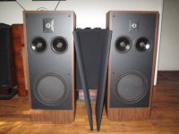
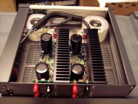
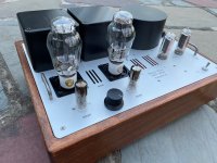
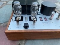
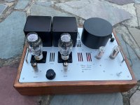
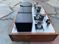
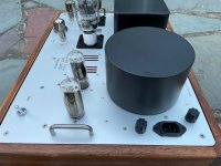
I have been given a Technics SU-V90D in an unfortunate state, completely disassembled and with a handful of components in a bag.
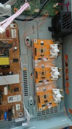
It has taken me a long time to start it up, it had a large number of broken active components, not only in the power stage, but also in the previous one, input selectors and even in the LED controllers.
After all these problems that have arisen in the repair, the ampli turns on perfectly, closes the protection relay and sounds really great with headphones, but with 8 ohm speakers a strong distortion appears.
There are no short circuits, no noises and nothing heats beyond normal.
In no case is there continuous current at the output.
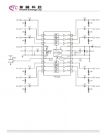
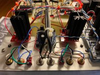
The problem I think is coming because I can't adjust the bias of the AB class exit stage. According to the manual, there should be + 1v and -1v in the driver bases. I have 2,8v at the base of the positive driver and 1v at the base of the negative driver.
Now the weirdest thing is coming: this happens with the standard operational, the M5219P. If I put another, like the NE5532, then I have -2,8v at the base of the negative Driver, and -1v at the base of the positive. With another quality opamp, the JRC2043D the voltage goes to 3,2v and 1,4.
I just tried an NEC 4570 and the same, 2,8v and 1v, both positive. I clarify that I have the operational ones with sockets, I don't know if it influences anything.
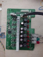
The voltages in the opamp IC 501 are correct except those mentioned, and correct are in the pair of output transistors.
I have reviewed, checked or replaced all the components of the bias circuit of a channel, since this happens in both channels at the same time, which puzzles me even more, since apart from the opamp IC401 they are two separate stages, and all the chip voltages are correct.
I have verified that the bias adjustment accentuates the problem, so I have it to a minimum.
All the semiconductors I use are 100% original, bought by ebay in Japan, Germany and the USA.
I read that this Technics technology consists of a class A amplifier followed by a power stage in class AB. I explain myself fatal, but I have read some documents on the internet to understand the operation of the amplifier.
As far as I understand, the class A part is working perfectly, as I say, with headphones it sounds spectacular.
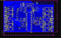
If you look at the scheme attached, the voltage amplifier goes to the output through a resistance of 1 Ohm.
I put the service manual in 3 RAR, is almost 10MB.
I have analog and digital scope, multimeter, audio generator and all habitual stuff.
Thank you for reading. Any input is welcome.
Regards!!!

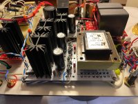
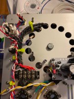
![PXL_20210112_160559011[1].jpg](/community/data/attachments/827/827943-57661cc0cfba0e2d698fceb9bcd02943.jpg?hash=V2YcwM-6Di)