Krill construction thread - 100W version

Hi all,
since the original Krill thread has become way too big I think that is better to start a separated thread dedicated to building questions and experiences.

This way the information for building a Krill amp will be easily available.

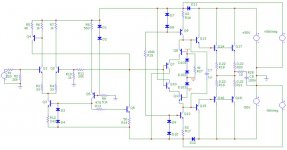
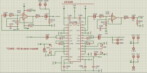
Attached the schematic for the 100W amp.

Some notes:
-R5 is actually a 100 Ohm fixed resistor paralleled with a 100 Ohm trimpot
-I omitted the 100Ohm//1K trimmers between the emitters of Q7/Q10 and the collectors of Q8/Q11 since these are not present on the boards.
-R27 is the bias trimmer

Ciao

Andrea

Attachments

  • 100w-mcap.jpg
    100w-mcap.jpg
    55.1 KB · Views: 5,327

Paralleling LM3886 output resistor question

Hi all, it’s been awhile since I posted, so if I’ve missed something or a pertinent thread I apologize. Anyhow, I got myself some 4 ohm speakers for Christmas and I’ve been using a standard LM3886 amp with a single chip for my 8 ohm but I’m planning on building an amp with two LM3886 paralleled per channel. I’m using the example parallel circuit in the LM4780 datasheet, and on the output it shows a 0.1 ohm 3W resistor on both chips. I understand it’s purpose there, but it doesn’t seem like 3W is enough for such a low impedance resistor on the output. Am I missing something?

Attachments

  • F4DCB0FE-E60B-491D-96B1-31A7EB45B125.png
    F4DCB0FE-E60B-491D-96B1-31A7EB45B125.png
    187.1 KB · Views: 242

Yet Another Adcom GFA-545-II Restored

Many of us somewhat long in the tooth and who display our gray hairs with pride recall the fondness with which Adcom amplifiers were treated long back. Many of the early amps had the signature of master designer Mr Nelson Pass in their DNA and quite a few models were hot favourites with those who cared for good sound and the ability to drive a variety of speakers well. Recently, after a huge gap of decades, again Adcom gear is finding favour with many and I too acquired a GFA-545-II. Though in non-working condition, I was hopeful of restoring it as a lot of help was available online.

The usual cleaning up of the PCBs, replacement of the electrolytics, checking/replacement of critical components etc breathed new life into it. But the previous owner/service man had tried many things and the amp was not behaving normally. I acquired a copy of the service manual and set out to systematically restore the amp. Soon another 545, in a somewhat worse condition, was acquired with thoughts of cannibalizing stuff for the better of the two. This soon resulted in a working amplifier, but one that had some erratic behaviour.

I had noticed thread where seasoned and experienced Adcom masters were tackling issues with the GFA-565 and posted an SOS there. The resulting exchange is posted here as a new thread. I am also requesting the Admins to delete all the 545-related posts from the 565 thread to do away with the 'thread pollution'.

The posts started with Post #395 on Page 20 on the thread:
https://www.diyaudio.com/community/threads/yet-another-adcom-gfa-565-thread.286742/ :

In order to benefit others who might want to explore working with the GFA-545-II, I am re-posting the entire discussion here in an orderly (though slightly edited) form. Warm regards and much thanks to the masters for all the help.
  • Like
Reactions: Philimon

WONDOM JAB3+ thump

I have a WONDOM/Sure JAB3+ amp and the demo program causes a thump on the line output when there is no signal every few minutes. It is a double thump. Biphasic?

I created a subwoofer program based off their demo and it does the same thing.

Clicking the mute button does not fix it. Disconnecting the external speaker amp from the JAB3+ does fix it which makes me think the problem is with the JAB3+ not the external amp.

Has anyone else experienced anything similar?

Playing music at really low volume also prevents it.

Old heatsink data

Hi there...

I was trying to make amp based on old magazine article and output transistors are mounted on heatsinks. I do not have actual data of thermal resistance so please help me if any of you have old catalogues. Heatsinks are:

Thermalloy 6430B and 6401B

or supplement:

Wakefield 403K and 410K

I will be very pleased with any information regarding thermal resistance or power/temperature rise graph.

Dubravko

2022 project: ALTEC A5

Hi,

On 1st January I bought a pair of A5/A7....what a way to start the year isn't it?
I had to try once.
No "intellectual" project in mind, they will be in my workshop.

What I bought:
Altec 828 clone with the two vertical slots
Altec 416-8C
JBL 2440 16 (but marketing right, they are 8)
JBL 2404H 8
ARAI 290 wood horn
A box filled od components for Xover, but a mess...

What I ordered:
I'm lazy so I ordered two Jagusk Xover crossed at 600Hz and 8500Hz

What I planned to do:
Make them sing, and working on the clone cabinet.
Made from Okoumé ply in 18mm, but the horn panels are really thin, will brace them.
Adding some damping stuff...

My question guys 🙂
1/In order to have them close as OG (crossover excepted ) I'm wondering if Altec 805 (tar filled) would be a better option than ARAI, less audiophile more indaguts thing?
I've a local opportunity for those, not too much money (gosh people are crazy about those 50s' Altec!!)
BUT is:
is this a good idea?
is there a way to use my 2440?

2/ best damping material for cabinet?

3/ share your thoughts 🙂

Thanks
Enjoy 2022

Attachments

  • IMG_7546.JPG
    IMG_7546.JPG
    319.4 KB · Views: 142

Why simple crossovers, tuned by ear, don’t work

It seems like almost every day we have a new person asking about online crossover calculators or ready made crossovers.

What we desperately need is a sticky that explains clearly why ready made crossovers don't work, but explained in a way that a person who has no understanding of loudspeaker design understands. Then all we have to do is link to the sticky. I'd do it myself but I think others would do far better job than me.

Anyone up for it?

6П15П-ЕВ / 6P15P-EV = EL803S / SV83 NOS, NIB (lot of 100pcs)

FS: 6П15П-ЕВ / 6P15P-EV = EL803S / SV83 NOS, NIB (lot of 100pcs)

Hi,

I have in stock excellent special quality electron tubes 6П15П-ЕВ / 6P15P-EV
= EL803S / EL83 / SV83

Index -EB means:
B = tubes of increased mechanical strength and reliability
E = tubes of increased durability (5000 hours or more)


Saratov factory "Reflector"
all the same date codes = Dec. 1976
minimum order = 100 pcs (one box)
price = $200 (i.e. $2 for 1piece)
shipping cost (2500 g)= $30 by airmail

Best regards!

-------------------
Olexandr
Kharkiv, UKRAINE
skype: OAA-1974

83905c4da4fc.jpg

dec57a828289.jpg

6ef194b05348.jpg

248f1d29206f.jpg

Usb microphone for voice and learning

Hi,

I want to build an usb microphone to use on my pc for remote working and podcast recording. If could definitively buy a blue yeti or any streaming microphone but I would not learn much from this.

Where I start from :
-I can solder SMDs, and work wood (and somehow metal)
-I can use kicad and already hade some PCB manufactured for me, but all digital, I come from a software / computer background and don't now much about analog electronic

I've seen this video that seems rather close to what I hade in mind : Building a quality USB-C microphone - YouTube . I have a few questions :
- should I replace the noname usb adc with e.g. a TI PCM2912A or wouldn't it change anything soundwise ?https://www.ti.com/product/PCM2912A
- the video uses a THAT1512 but that5522 or TI INA849 seems to be newer / better SNR version. Any reason not to use them ?
- he uses a jli-2555 capsule. Is there any close quality capsule I could buy from aliexpress (the $13 jil233 will probably cost about $45 once i've paid shipping, vat and custom fees. Buying on aliexpress I can have almost free shipping shipping and pay the VAT directly so I won't have custom fees)

Thank you,
windless

Tube Phono PCB - Improved WAD Design

I dub thee 'Tres Phono'! 😎

This is based on the WAD phono stage which is a very well known and excellent sounding phono stage! I improved upon it by using better components and adding a fully-regulated B+ and filament supply. All on a single PCB so all you add is a choke, power transformer and connectors. This went head-to-head with a highly modified EAR and blew it away. Very neutral stage and dead quiet! Also has provisions to add tuning caps to perfectly tune the RIAA points if you have the equipment to do so. PCB designed so parts can be on top or bottom if you want tubes exposed on a chassis. Purchase a PCB and I'll include the schematic and BOM. Part cost was just shy of $300 excluding tubes and chassis parts before the crap hit the fan with component availability.

$35 each shipped to USA. Contact me for international shipping.

Attachments

  • Tres Phono copy.jpeg
    Tres Phono copy.jpeg
    302.9 KB · Views: 248
  • Tube Phono Parts copy.jpeg
    Tube Phono Parts copy.jpeg
    279.5 KB · Views: 220
  • Tres Phono Built copy.jpeg
    Tres Phono Built copy.jpeg
    269 KB · Views: 244

pass x2.5 problem

Hi all ! Summer time in Greece(hot) and my beloved pass pre is refusing to follow the orders I give ,either with push buttons nor with remote. When turned of and let cool down it is back in use. When hot again ,after 5 hours in mains the problem appears again. I opened the lid and by spraying the processor chip(the one mounted in a base) with 'freeze ' spray everything works fine. I guess I need a new chip probably by pass labs . I would like help to get it somehow , thanks !
Greetings to all!

relative SPL front and back of a speaker at the baffle step frequency

At some very low frequency where the wavelength of the sound being reproduced by a closed- back (sealed) loudspeaker system is much greater than the dimensions of the speaker box, the sound pressure level (SPL) measured behind and in front of the speaker system is the same. That is, the difference of SPL readings front and back equals 0 dB. My question is, if frequency is increased to be equal to the baffle step frequency of the speaker system, what then is the difference of SPL readings front and back?

Please don't ask me why I want to know this; I have my reasons which I would rather not bring into the discussion for now anyway. Just think of it as a challenge to your understanding of the acoustics of closed-box loudspeaker systems.

This is a question excluding the open baffle or dipole type of speaker system.

Regards,
Pete

Lowest safe loadline: what is the limit?

I'm designing a amp to see the limits of a new feedback system, and I would like to know what is the limit you consider on the lowest side for the loadline.
Please consider that the DF has not to be considered here.

The amp is a PP based on a pair of EL34 at 450V B+.
Initial OPT was 6k6 with UL 23%, now I would like to test a 4k with UL 23% I have, but I would avoid to blow a pair of EL34.

attachment.php


The point is that the loadline is on the edge of 2x the max plate dissipation on some points (as highlighted on the image) and this considering a load of 8 Ohm, so it's even worst at mid frequencies where load is usually lower.

What is the limit you consider when you design an amp?
Is that loadline the lowest you'd use, not considering the DF in the equation?

Thank you in advance,

Roberto

Attachments

  • Loadline 450V 4k.png
    Loadline 450V 4k.png
    57.5 KB · Views: 1,751

Microphone Isolation Panel instead of Rear Absorbtion Pads

I'm looking into Accoustic treatment for my room, so far I've just put thick blankets over the side walls, nothing spectacular, but for $200AU or so, I could get four sets of these:

https://www.ebay.com.au/itm/12-Pcs-...349624.m46890.l49286&mkrid=705-154756-20017-0
It's enough to spot cover the ceiling, side walls, and a few directly behind the drivers on the fronts.

And I was thinking one of these:

https://www.ebay.com.au/itm/25-7cm-...349624.m46890.l49286&mkrid=705-154756-20017-0
For the rear.

I'm thinking a mild concave shape, slightly angled up perhaps?, it would sit between the two lamps, between me and the clay moulds, this could just remove all of the rear reflections.

My listening seat is a 2m x 2m couch, so no floor reflections 🙂

What do you think? Has anybody tried something like this?

Edit:

So tonight I put some large cushions roughly the size of the array in the place I was going to put the array, and also some makeshift bass traps in the only two available 90° corners in my (assymetric) room.

With some foam bass trap corners It'll be a good $250 purchase I think...

https://www.ebay.com.au/itm/Alpha-2...349624.m46890.l49286&mkrid=705-154756-20017-0

Attachments

  • IMG_20220109_070225.jpg
    IMG_20220109_070225.jpg
    385.5 KB · Views: 128
  • IMG_20220109_195526.jpg
    IMG_20220109_195526.jpg
    312.5 KB · Views: 82
  • IMG_20220109_195548.jpg
    IMG_20220109_195548.jpg
    296.1 KB · Views: 82
  • IMG_20220109_195535.jpg
    IMG_20220109_195535.jpg
    249.3 KB · Views: 87

Harmony H205/Silvertone 1342 OT

Starting my first classic amp restoration and have an output transformer question.The Harmony H205 amp I bought, had the OT replaced with a 16 ohm output sub. It’s a 6V6 pp circuit, rated at 12W I believe?. Haven’t gotten to the point of powering it up yet, but will obviously need a better OT. That orange cap needs to go too:yes:

This amp has the original Rola 12”, 3.2 ohm speaker. Any suggestions on a quality OT would be greatly appreciated. Want to do justice to this classic.

Attachments

  • 4EC71DFD-39C9-4619-AD97-963740E8DB3A.jpg
    4EC71DFD-39C9-4619-AD97-963740E8DB3A.jpg
    812.4 KB · Views: 253
  • BA33FDEC-7BDD-4F8A-A088-057C758871CF.jpg
    BA33FDEC-7BDD-4F8A-A088-057C758871CF.jpg
    393.1 KB · Views: 244
  • B2B8E6BC-6EE5-4CD2-9E74-F759038C9B47.jpg
    B2B8E6BC-6EE5-4CD2-9E74-F759038C9B47.jpg
    994.9 KB · Views: 307

FS TWTMC D-TWTMC D&D-Maxwell Supercap

For sale:
1 x TWTMC D Driscoll assembled with SC Cut 11,2896 MHZ Crystal
21/36/15wi.jpg - Visionneuse Zupimages
1 x TWTMC D Driscoll 24,5760 MHZ assembled (no Crystal)
21/36/irk7.jpg - Visionneuse Zupimages
1 x TWTMC D&D Daugther board assembled
21/36/lwhw.jpg - Visionneuse Zupimages


4 x LDOVR 3045-S Regulator 2x3,3 Volts - 2x 6,6 Volts
21/36/owpv.jpg - Visionneuse Zupimages


2x Supercapacitor Maxwell 2000 Farads 2,7 Volts
21/36/ayoj.jpg - Visionneuse Zupimages

Reasonable price to negotiate with the buyer.

Guesstimating transformer power ratings

Hi,

in the past two years I've harvested a bunch of power transformers from some cheesiy sounding and crappy Hammond transistor organs. Sadly, I didn't have a close look at their badges and the power consumption that might have been written there, but anyway, all these organs featured Leslie or Rotosonic units whose motors are of unknown power consumption as well.

The 1st pic shows a pair of identical trannies, Hammond part # 003-054471, coming from a Collonnade and a - smaller - Aurora Classic. Their lamination stacks measure 105 x 87 x 55 mm (4 1/8 x 3½ x 2 1/4 "):

20211220_125801_res.jpg

Next one is the tranny of a notably bigger Concorde. Part # 003-046819. Lamination outline is the same, but stack height is a bit lower: 105 x 87 x 50 mm (4 1/8 x 3½ x 2 "):

20211220_125959_res.jpg

Next one came form a Model 8022 organ. Part # 003-048011. Laminations measure 95 x 80 x 50 mm (3 3/4 x 3 1/8 x 2 "):

20211220_130206_res.jpg

The next pair also was in the Colonnade and Aurora organs. Their primaries are 115 Vac, secondary is 14 Vac. Perhaps they might serve in a BTL pair (2 x 2) of amplifiers. Part # 003-054853, laminations are 76 x 63 x 41 mm (3 x 2 1/2 x 1 5/8 "):

20211220_130113_res.jpg

The smallest one. Part # 003-046374, laminations are 66 x 56 x 26 mm (2 5/8 x 2 3/16 x 1 "):

20211220_130246_res.jpg

Finally a 117 Vac power tranny that came from a Leslie 121 multi channel amplifier. It powered four almost identical amplifiers, consisting of a 12AU7 and a pair of fix biased 7189's each. This is the one I was referring to in my proper winding technique thread. I'm planning to rewind it as an OT of about 40 W power. Laminations are 114 x 95 x 33 mm (4½ x 3 3/4 x 1 1/4 "):

20211220_130346_res.jpg

Which power capabilities can I expect from these transformers?

Best regards!

  • Poll Poll
Which DIY speaker for metal/rock (newer, well-produced)

For metal/rock, PE Amiga or DIYSG Helix Dome TM?

  • PE Amiga

    Votes: 0 0.0%
  • DIYSG Helix Dome TM

    Votes: 2 100.0%

Which DIY speaker would be better for newer, well-produced metal/rock (Periphery, Jinjer, Born of Osiris, Sevendust etc), the PE Amiga or DIYSG Helix Dome TM? The lows below 50hz will be crossed to a sealed HSU sub.

Help with Audiolab 8000a Mk1 information

Hi all!
Long time scroller, first time poster here.
I flippin love this forum - general thanks to all involved.

So: I got a cheap Audiolab 8000a on feebay.
Serial number is faded but looks like 667038.
It has Din sockets, and AFN8411 outputs - Early version.

Right channel has had magic fairy smoke escape predrivers, and some resistors.
I have not had a proper dig around yet, but seems to be a common problem.

Questions:
  • Does any kind (or not) soul have a Mk1 service manual?
  • Anyone know anything about the AFN8411 mosfets? Very little info out there regarding replacements.
  • Has anyone replaced blown predrivers / drivers / outputs on this model with new or available devices.

Any thoughts and opinions about the amp are welcome.
Thanks!

Bipolar coupling caps

Could there be any harm using these?
Any benefit over polarised?
I guess, there might be a benefit, if i try to maintain high signal level voltage in the system (bipolar psu opamps)
Here is the curcuit (attached).
What if I keep only the input caps (the digipot input)?

Would the shunt resistors at the opamp input/ output make problems if there is a dc offset and dc coupling (without coupling caps10uf)
I mean, the dc offset would cause small constant current through the 68k(input) and 10k(output).
Would that cause noise or make the digipot distort (dc coupled,loaded with 68k)?

Not sure if the digipot(some cmos matrix) coul have a dc offset

Attachments

  • IMG-d943bbcc1f483f48a3e95dfb424f0b73-V.jpg
    IMG-d943bbcc1f483f48a3e95dfb424f0b73-V.jpg
    196.8 KB · Views: 153

Power amp PCB layout - GND pour on both sides?

I've been working on a Baby Huey stereo pcb. Everything on one board just like Pete Millett's DCPP: https://www.diyaudio.com/community/threads/el34-baby-huey-amplifier.326920/page-68#post-6891898

Should I have a GND copper pour on both sides?

Pete has only top. I can see that having two pours could cause further ground loops, but there are a couple of 'islands' that aren't as connected as I'd like. Might not make any difference though.

I'd appreciate if someone more knowledgable in PCB layout could take a look and check for any howlers. I'm sure there are improvements to be made, but I think 'done' is better than 'perfect'.

Images and schematic attached.
Interactive view here: https://www.tristancollins.me/diyaudio/ibom.html <- probably easier to see the traces
Source files here: https://github.com/tristancollins/HiFi-BabyHuey

Thanks,

Tristan

Attachments

  • BabyHuey.pdf
    BabyHuey.pdf
    676.8 KB · Views: 105
  • BabyHuey.png
    BabyHuey.png
    690.9 KB · Views: 113
  • BabyHuey_underside.png
    BabyHuey_underside.png
    564.5 KB · Views: 123

Help! Is it the power supply, or something else?

Hy
I'm probably silly but I'm trying to make it work.
I have a small headphone amplifier that requires +12v ground - 12v.
I have 3 power supply's without the ground connection. (just + -)
If I conect it like this, (just + -), it doesn't work. If I mess around with - on the ground for a sec, I have sound (poor sound).
Taking a separate wire to the wall outlet (ground) doesn't help.
I am afraid that I will try stupider and stupider things until I break it.
Help...(I am also a nuby, just to make things clear).
Thank you!

Goldentone single valve guitar amp troubleshoot

HI this is my first post as a newb here so hoping Ive landed this in the right place

From time to time I've DIY racked and fixed old pre amps, tube pre amps etc but only at a pretty basic level (eg cap replacement, basic signal tracing etc) and not where I would be taking any chances with the circuit beyond what I know. Also very aware of the dangers with high voltage here.

Been reading up on tube operaton and my physics is not great but understand the basic concepts to a point…

I’m just troubleshooting what I initially thought was a bad connection in my single valve (6gw8) Goldentone guitar amp ( Aussie practice amp from the 60’s). Attached is a link to a schematic (with thanks to J Mumford and C Lilly) that is pretty much identical to my amp except for one or two resistor values.

https://www.ozvalveamps.org/electravox/60s electravox single valve amp-p-jm.jpg

I think a good chance I’m dealing with a bad tube but I have swapped out another tube and both show identical symptoms. Before I go searching for another 6gw8 I was wondering if it could be a different problem eg.bias /voltage/ ac ripple?

Symptoms as follows….
Initially signal faded and disappeared after a certain amount of playing but was an intermittent thing..
Was able to bring it back temporarily and intermittently by addressing contact/ solder at tube pins but now the output is consistently weak have tensioned socket etc to no avail.

The triode stage appears to be amplifying as it should and a good signal goes in to the grid post volume and tone pot at the pentode stage but comes out weak and distorted at the anode (which makes me think either something wrong internally with the tube or some issue with voltage /current/ bias?)

Attached are some photos on my old oscilloscope showing a 440hz sine wave coming in and at the final stage before it hits the output transformer.


I took some voltage measurements at key points in reference to the schematic as well….


Voltage at triode plate (C) is 147vdc (schematic indicates 82vdc ) stock resistor from point B to C on my amp is 100k (not the recommended 220k)

Screen Voltage at Point (B ) is 260vdc (recommended is 250vdc)

Plate voltage at pentode (A) is 320vdc (as opposed to recommended 309vdc )

Heater voltage is 7.02 v ac (measured from pin 4 to 5) recommended is 6.2 vac

Btw I did see some ac on the (A) voltage but not a huge amount

Original caps replaced a few years ago

Scope pics attached and finally a picture of the tube glow if that helps : )


Just thought this might be a classic indication of either bad tube or another common symptom ? Not sure… if anyone has the time to share expertise on this that’d be really appreciated!

Thanks

Tim

Attachments

  • input signal before amplifier.JPG
    input signal before amplifier.JPG
    83.7 KB · Views: 262
  • signal at triode plate.JPG
    signal at triode plate.JPG
    100.8 KB · Views: 252
  • signal at pentode input.JPG
    signal at pentode input.JPG
    92.8 KB · Views: 264
  • signal at pentode plate ouptut.JPG
    signal at pentode plate ouptut.JPG
    82.8 KB · Views: 274
  • valve glow.JPG
    valve glow.JPG
    85.2 KB · Views: 273

  • Locked
High End pseudoscience. Electronics and enclosure marketing vs speaker efficiency

High end, High fidelity or Audiophile terms are just product of misinformation wars, that were created in the WW2 to manipulate reality and build national sentiment and morale to recruit soldiers and win wars, and this has expanded from politics to create an eternal voting ping-pong and to advertising creating an eternal consumer toddler. An the audio consumer segment is probably one of the most filled with pseudoscience and misleading, without showing real data of the products.

We watch attractive adverts with speaker cabinets and electronics with good picture presentation and supposed great technology, we want to own them like retards, me included today as I can fall for it so easily.

So let's talk about real facts about sound science and the most critical factor in sound transmission is efficiency and this is a problem with speakers because no matter how good the audio format, bitrate, bit depth, DAC, amplifier, speaker cone, enclosure is, we burn 99% of the sound and the speaker transforms only 1% from energy to sound, lets say with a 8ohm speaker at 92db sensibility, and this is what matters most.

So with a 3db increase at 95db we have a 2% efficient speaker and if we increase the sensibility to 131db that speaker is 13% and we can play the sound low and hear most of the sound details with an mp3, flac, DVD-A or DTS-MA.

The ways to accomplish speaker efficiency is with speaker sensibility and area, Xmax, horns and enclosure type and volume while electronic efficiency is made with gain structure and also by removing passive crossovers and using class D,T, etc amps with 90-100% efficiency. However the most noticeable methods for speaker db increase are horns and gain structure.

In my case i use gain structure with Foobar at minimum while windows preamp and amp at maximum, reducing amp volume and raising foobar to reduce noise at low volume, however i can use any small speaker very loud without cone excursion or play loud a big subwoofer with a 25w class-D amp board

By reducing the source volume I am supposed to eat bit rate and bit depth, but the music gains richness so when i use a common setup with amp+speaker with amp at low volume it sounds poor whatever the "quality" of the components.

The main drawback of this gain structure is that i can blow the speaker if i raise the foobar volume or windows play any sound suddenly. There's a notable difference by using DVD-A instead flac in Foobar and i can raise the volume and the richness of the sound and low distortion its quite noticeable, the same with dts-ma.

munich20170519_high_end_20170064.jpg

maxresdhhefault.jpg


TDA7492P-25w-25w-Digital-Class-D-Amplifier-Board-Power-Audio-Amp-3-5mm-stereo-headphone-plug_j...png
inbnhdex.png

f4ca58037f63df1a763a7c45cc2b586d--ue-boom-speakers.jpg


xywk3Zl.jpg

Simple DIYable Waveguide testing (dome tweeters)

Hi All,

I have been doing some testing with shallow waveguides for my BaSSlines project that I thought you all might be interested in. I posted this in my BaSSlines thread, but realized many of you who might be interested could miss it there. I created an insert into the baffle that would allow me to make multiple WG's and insert them into the same baffle (see photo below), with same tweeter, same mic setup, position, etc. The tweeter is the Peerless HDS with the face plate removed. The tweeter is mounted by pressing it to the back of he WG cutout, held by a woof fixture. The measurements were all taken at 1 meter, with the mic 80" high, in the center of a room with vaulted ceilings probably 15' high at that point and with a 4ms gated window.

All the WG's were created from mdf by boring a hole with a forstner bit, then rounding over the appropraite amount and then routing from the back for the palnned depth of either 1/2" deep or 3/4" deep in these cases. These are something just about any DIYer can build petty easily, which was the idea. There are a few tricks to doing this, most notably, when using a 3/4" rounvoer bit, you have to have a backer piece to you mdf baffle that you also bore a hole through. This backer piece is needed for the bearing of the deeper 3/4" roundover bit to ride on. All the bore through holes on these were adjusted so the final throat sizes are about 1-1/4" +- 1/32" at the final size.

Most of the plots show the waveguide perfomance at 0-15-30-45 and 60º of axis horizontally, so you can see the effect on axis and the directivity off axis. The first plot is the HDS with a standard flush mount. My goal with the waveguide is to get some boost at the low end so that when qualized out in the crossover you get the possible benefits of lowered distortion, slighly higher sensitivity, better off axis directivity and a counter to the typical rising responce of the HDS tweeter on axis, which might be fatiguing to some over time. Also included are some comparisons of the favorite WG results on axis with each other.

I'll include some photos of the waveguide testing insert setup in this post and in the next one I'll post the results.

DSCF0169.jpg

DSCF0171.jpg

DSCF0175.jpg

DSCF0174.jpg

DSCF0144b.jpg

looking for bare board nice phono preamp

I am interested in building my own phono preamp for fun
I don't want to spend a fortune but don't want junk, I also don't want to design the circuit or the board

does anyone have experience with either of these boards ? I want to buy my own components so I can make sure they are genuine quality parts.

https://www.ebay.com/itm/322433557552
https://www.ebay.com/itm/292226282737

Cheap eBay subwoofer amps

There are some cheap, cheap $40 car subwoofer amps suggesting around 1,000w or more. I bought one (PA-80D) to pair with a decades old but very capable DELL 1,100w PSU from a server -- something you can find for $20 from one of many server liquidators. I received the amp and found 8 switching devices, emailed the seller, and was told that it uses the Toshiba 5198 1941 chipset and does around 300w RMS. It seems like a well-built unit and for $60 all-in, decent value for 300w RMS. I'm still looking for a budget 1-2kw solution...

20220104_073348.jpg

Attachments

  • 20220104_073403.jpg
    20220104_073403.jpg
    502.1 KB · Views: 147
  • 20220104_073414.jpg
    20220104_073414.jpg
    375.7 KB · Views: 136

TC9FD18-08 Pair and Orphan CHR-70.3 which DIY speaker?

Because of new business ventures didn't have much time to come to DIY Audio for a long time, so rusty as far as speaker design go, but have more time on my hands and ready to do some builds, including a redesign of a hybrid (vented wooofer with an open baffle full range) as to make it better. Anyways, in my main listening room I have a pair of Sonus Faber Venere 2.0 bookshelves that thought wonderful sounding paired to my Arcam SA-10 they are simply too large for my room and you can feel it mostly in the amount of bass output. So, those speakers will be relocated to another room and in need of speakers that shine on a small to mid size room (12' x 20') with the listening position located some 10' from the speakers. Anyways, my hybrids would work great there, but they need bi-amplification; I will redesign as to make new enclosures that can acommodate DIY 520Hz 2nd Order Passive X-Overs with -4dB Attenuation.

As for my main listening room I can make DIY Speakers with Full Range drivers (my preference). In my parts bin I have a pair of TC9FD18-08 and a single CHR-70.3 for which I can just buy a second one. I also have a pair of 3" TABAQ Enclosures that I can just put drivers into. What design do you guys prefer or recommend for the TC9's? Should I get a second CHR-70.3 and build a speaker with them, which one? Or, should I just get a pair of new 3" Full Range Drivers for the TABAQ enclosures and maybe just add a BSC, which drivers? Approx. $100.00 total budget for new drivers. Your help and knowledge is greatly appreciated.

8 or 10" subs for sealed venture?

I'm putting another 2.2 sub setup together. - two mains + two subs. My Dynaudio upper middle tier stand mounts don't miss bass notes they play the whole spectrum really well. I'm currently running 250 clean watts to each stand mount in 4 ohms.

The listener is needing more impact. While avoiding damage to my loved Dynaudios. I'd like to feel the sonic waves more while listening.

I have a two channel class D Crown xls, but I have not chosen subs.

Peerless 10" worked well in two sealed applications. But I also employed sealed 8's that I was happy with.

I'm pondering twin 8's (two per box in left and right channel sub).

8 ohm in parallel for two 4 ohm loads. Pretty basic straight forward configuration.


Unless there are some good 8s out there since I've played with subs. That are high power handling but not necessarily high dollar and hard on the wallet. Perhaps I would be happy with single 8s?

In terms of sound I could use a little guidence wich direction to go. I'm leaning towards 8s. I do like the thought of twins in separate boxes.

Speaking of such a design, would I get better performance if I were to separate the boxes inside to make 2 equal sized chambers effectively making each sub box "two channel"?

Or is there no benefit compared to twin subs sharing one entire sealed box, without obstruction, no channel divider.

Interesting "archeological" find

I am in the process of sorting out my "hardware archives".
In doing so, I stumbled upon a very unimpressive prototype, dating back from the pre-2000, pre-sim years:

OldTim1.jpg


OldTim2.jpg


OldTim3.jpg


One shouldn't judge it based on its shaggy looks though: I tested it, and it performs surprising well.
Like most of my amplifiers, it has some kind of auto-bias circuit.
Very often, the auto-bias introduces unwanted artifacts, especially in the crossover region.
To evaluate the quality, I tested it under low voltage amplitude, high current, high frequency conditions with a 50kHz triangle wave and a 2 ohm load:

OldTim4.jpg


The result is pretty immaculate!
The quiescent current for the total amplifier is ~200mA.
The circuit is stable, clean and tolerant and could serve as a starting base for a real amplifier.

Even better, I managed to reconcile the physical circuit with my paper archives (an outstanding feat!):

OldTim5.jpg


The circuit is not ultra-simple, but it isn't ultra complicated either.

Faital 6FE100 TL

Hi there!
A question, why I ended up with a 43Hz tuning instead of 63Hz as calculated?
Line not filled but lined with 1" thick noise reduction felt

Attachments

  • Faital TL.png
    Faital TL.png
    21 KB · Views: 686
  • Woofer Z in box.png
    Woofer Z in box.png
    71.8 KB · Views: 655
  • 130826312_209868204108922_5458022912079876372_o.jpg
    130826312_209868204108922_5458022912079876372_o.jpg
    8.3 KB · Views: 989
  • 130867735_209868800775529_2967649852867733742_o.jpg
    130867735_209868800775529_2967649852867733742_o.jpg
    8.1 KB · Views: 675
  • Woofer 30 deg. in box response.png
    Woofer 30 deg. in box response.png
    79.1 KB · Views: 651
  • Param.png
    Param.png
    152.5 KB · Views: 563

FS: First Watt F3 assembled boards + power supply + transformer

I am selling my F3 boards, and power supply plus transformer.
The 10000uF output capacitors are not included because I didn't need them, I used these only for higher frequencies.
These are tested and all the adjustments done.
In one picture I show how I installed LU1014 on the heatsink. I will provide that bracket.
I also have the power supply with 8 x 22000 uF capacitors and the toroidal transformer from Toroidy, which i found the best.
If you want I have also the bare PCB for F3 and power supply.
PM me for prices, I can sell these individual if you want.

Attachments

  • tempImageytMfTt.gif
    tempImageytMfTt.gif
    1.3 MB · Views: 191
  • tempImageUOkGe4.gif
    tempImageUOkGe4.gif
    986.6 KB · Views: 190
  • tempImagefj7Vyj.gif
    tempImagefj7Vyj.gif
    1.3 MB · Views: 171
  • tempImageoKUJnE.gif
    tempImageoKUJnE.gif
    1.2 MB · Views: 175
  • tempImagedyqUiD.gif
    tempImagedyqUiD.gif
    1.6 MB · Views: 187
  • tempImageBvYHuM.gif
    tempImageBvYHuM.gif
    1 MB · Views: 171
  • tempImageAM2Q9a.gif
    tempImageAM2Q9a.gif
    1.3 MB · Views: 184
  • tempImagek1YgQv.gif
    tempImagek1YgQv.gif
    806.4 KB · Views: 175
  • tempImageGh0IM8.gif
    tempImageGh0IM8.gif
    1.5 MB · Views: 194
  • tempImagejWWyYz.gif
    tempImagejWWyYz.gif
    1.1 MB · Views: 181
  • tempImageiMqJUS.gif
    tempImageiMqJUS.gif
    1.1 MB · Views: 176
  • tempImageRpGdTe.gif
    tempImageRpGdTe.gif
    1.3 MB · Views: 165
  • tempImageSf0piV.gif
    tempImageSf0piV.gif
    1.2 MB · Views: 159
  • tempImagen3uLcp.gif
    tempImagen3uLcp.gif
    1.3 MB · Views: 177

Requesting assistance for a Fostex FE168e∑ cabinet design

Hi!

Fore note: This is a forum with a lot of hobbyists who provide a lot of free information. I also understand this request would take someone with knowledge time to come up with results, so I'm happy to compensate if requested. I simply don't have the time in my lifetime to learn the dark arts of audio wizardry 🙁

Aim: I would like to rebuild some full range FE168EZ sigmas BLH cabinets. Not like the Fostex recommended cabinets I built a decade ago. Just nice curves and smooooooth surfaces everywhere using CAD & a 4x8ft CNC.


Objectives:
1. Build a Full range BLH unless there's a better recommendation out there for this driver. Down to 50-70hz is good.
2. Have the driver set about 3.5ft/107cm up from the floor
3. I'd prefer having two identical horns come out from the back chamber. One eventually exiting at floor level, the other up top about 7ft/215cm high
4. The total horn mouth area to be less than 0.2sqm
5. Any audio reasons to not build these out of concrete or poured resins?

DATA (in metric or imperial is fine) I am seeking unless you suggest better alternatives:
1. Having a "Back Chamber" volume and shape similar to the B&W Nautilus
- I'd need A cross-sectional curve profile for a straight taper or a shape/equation curve to follow with a recommended volume for this chamber.
2. A suggestion for a good position of the throat/s relative to the back chamber.
- A simple sketch or descriptor
3. Total throat/s area and whether it needs a smooth or sharp transition from the back chamber.
- m^2
4. The length of the horn and either its curve plot or the cross-sectional area at regular intervals
- eg. Total cross-sectional areas at 10cm intervals
5. Is the cross-sectional shape of the horn best circular or eggshell or twisting eggshell to limit standing waves? When it reaches the horn mouth do I taper the cross-section out so it has a flat edge meeting the floor, or do I just continue with the same prior cross-section shape to finish facing forward?
- A simple sketch or descriptor
6. any internal/external features to add at the tip of the horn mouth like a rounded edge or a flat plane?
- A simple sketch or descriptor
7. any external features to add as the driver meets the back chamber such as a flat plane or chamfered surface?
- A simple sketch or descriptor
8. other bits of information that'll be useful?

Thanks for reading!

https://www.fostexinternational.com/docs/speaker_components/pdf/fe168ez.pdfhttps://www.fostexinternational.com/docs/speaker_components/pdf/recom_enclose/168ez_enclrev.pdf

Power supply theory?

Hey All,

Put on your "Double E" thinking cap and give me your opinion on this.

Now I was weened on audio electronics in the late 70's, and for the past 40 years or so I've designed, built and repaired a lot of stuff, but I just ran upon something that baffles me.

A guy brought me a powered sub-woofer to fix, and there's something about the power supply that I don't get.

Look at this schematic, the transformer has two secondary's, the top one is a single ended higher voltage that feeds the power amp, (which is also a strange design).

But look at the bottom secondary, a lower voltage "center tapped" winding that feeds two typical bipolar zener supplies off the same bridge rectifier, each one supplies a few opamps (I guess the designer thought it was more cost effective to double the parts count rather than using bigger parts, like a 1N4744 which has twice the current of the 1N5245, and 1/4W 330 ohm resisters instead if 1/8W).

But look at the center tap, it is fused to the chassis ground (what?).....

So if some over-current event happens and blows the fuse,

IF all the components are still good, but the supply's no longer reference to the center tap,
THEN in theory, does this become a "dual voltage" supply instead of "bipolar"?

That is, does the negative rail become 0V, and the chassis ground become +15V, and the positive rail become +30V?

OR IF a zener on the negative rail is shorted, THEN the negative rail become 0V, the chassis ground becomes 0V (due to the shorted zener), and the positive rail becomes +15V?

OR IF a zener on the positive rail is shorted, THEN the negative rail becomes 0V, the chassis ground becomes +15V, and the positive rail is also +15V (due to the shorted zener)?

Am I missing some obvious "good design practice" here, or does this look as goofy to ya'll as it does to me?

JohnR

1641219219395.png

My best upgrade ever!

It's a fact that few of us can make cabinets to the cosmetic standards of the major manufacturers. And back in the day when Sony wanted to be 'high-end' they made some high-end speaker cabinets. But the designs of these cabinets made them very retro very quick.

Over the years I have tried many alternatives but the bookshelf speakers that come with the Sony SS-CPX1 are my preferred fronts, the deep cabinets and Kevlar drivers representing the sound I like. The problem is that in 2022 they so effing butt ugly that divorce lawyers salivate at the thought of me keeping them in house.

I bought a pair of Wharfedale Diamonds but they weren't 'it'.

The solution cost $3 and 2 hours.

sony5.jpg
sony5.jpg
sony5upb.JPG


Seriously I didn't think $2 of spray paint and dab of sugar soap would change my life. Trust me, at home, I now get lucky - a lot.

Attachments

  • sony5upa.JPG
    sony5upa.JPG
    205.9 KB · Views: 330

Capasitor behavior on crossover

Hello! Hope someone could help me out, and hopefully I can explain myself clearly enough my English is not so good.
I'm wondering how would capasitors behave on high pass filter where is three speakers and three capasitors and all capasitors are for high pass use. I draw a 'pretty' picture about the circuit. R1, 2 and 3 are the speakers.
I would need a filter where C1 cuts off freqs under 80hz, C2 and C3 cut off freqs under 4000hz. C2 cut off freq is not so important..let's say somewhere between 2-6khz

Attachments

  • IMG-20220105-WA0035.jpg
    IMG-20220105-WA0035.jpg
    62.5 KB · Views: 114

Heat for humming bird feeder ?

Need a wee heater for my Feeders. saw something where 4 ...100 Ohm 1/4 watt resistors ( parallel) epoxied to underside of feeder provided 1 watt heat off of a cheap /ubiquitous USB power wart.
What resistor assembly could produce say 1.5 to 2 watts on a 5 v 1 amp or even 12 V 1 amp wall wart ? Have a few unused ones on hand
Hey.. this is what old guys fixate on.. apologies.. if not strictly Audio.

For Sale Transformers for tube projects, Hammond, Edcor

Edcor GXPP-10-8-8K Pair (used) -- New cost: $115. Asking $30 (low price due to short leads)
Edcor XPWR152 (new) -- New cost: $64. Asking $40
Edcor CXPP25-MS-8K/23% Pair (new) -- New cost: $194. Asking $160
Hammond 370FX (like new) -- New cost: $~120-130. Asking $80

AnTek AS-1T250 (like new) -- New cost: $38. Asking $25
Hammond 159T choke (new) -- New cost: $32. Asking. $20

Shipping not included

Attachments

  • 2022-01-02 17.57.15.jpg
    2022-01-02 17.57.15.jpg
    388.6 KB · Views: 138
  • 2022-01-02 17.58.07.jpg
    2022-01-02 17.58.07.jpg
    344.8 KB · Views: 137
  • 2022-01-02 19.00.51.jpg
    2022-01-02 19.00.51.jpg
    361.8 KB · Views: 137

NEC 2SA539 transistor replacement/equivalent?

Hi DIYers,

I’m looking for a replacement for the NEC 2SA539 PNP channel transistor, TO-92 package. The pinout of a replacement won’t matter, I can bend legs. The KSA539 is unavailable, much like the original.

The original specs are as follows:

Maximum Ratings:
Collector to Base Voltage (V CBO) -60V
Emitter to Base Voltage (V EBO) -5V
Collector Current -200mA
Dissipation 250mW

Characteristics (at conditions: V CE -1V, IE -50mA)
Current gain hFE 80
fT 200Hz
Cob 8.5pF
hie 20 Ohms
Collector Cutoff Current I CBO, max 0.2uA, V CB -30V

Wavecor 2 way

I have a pair of 4 ohm Wavecor 8”( http://wavecor.com/WF223BD01_02_specifications.pdf) and wondered what would be a good choice of a dome tweeter to go with in a 21-26L sealed box? Is there anyone that would be willing to help with a crossover design that will get me in the ballpark, I will happily compensate. I don’t as of yet have measuring tools but plan on purchasing soon.

Help troubleshooting Cavalli Liquid Carbon

Hi,

I have a Cavalli LC which recently stopped playing music. There is a pulsating sound coming out of the headphones which sounds like a slow motion helicopter in the distance.
There are two push buttons on the front of the amp. One for choosing balanced or SE input, and one for 1x or 3x gain. When I push any of those, the frequency of the pulse is doubling.
You think I have any chance of fixing this with only a soldering station and a multimeter?

If so, where would you start searching for fault?

Best

Theo

Attachments

  • CDC5AC1C-CEE1-4917-9231-42E703ABCDBE.jpg
    CDC5AC1C-CEE1-4917-9231-42E703ABCDBE.jpg
    823.3 KB · Views: 507
  • F8833DDD-516F-4C0C-991A-206DF9055137.jpg
    F8833DDD-516F-4C0C-991A-206DF9055137.jpg
    745.3 KB · Views: 396

Troubleshoot Cavalli Liquid Carbon imbalanced

Hi, everyone

I just bought a pre-owned Cavalli Liquid Carbon (V1 not massdrop) from Head-fi

The first day is fine, but in the second day when I turned it on I found my LC have some problems with the volume; btw I used 6.3 jack, the sound from left channel is super large, like turn the volume to 10-12 o'clock and I can not adjust it
After couple mins, the sound from left channel became lower, but still when I turn the volume all the way down to minimum I still can hear some sound from the left channel.

Anyone had this problem and replaced it themselves? Or any recommendation for fixing it?

Thank you guys
Ryan

What kind of VAS is this

Greetings!

About a year ago a fellow here helped me to make this crapy amplifier, which works suprisingly well.
I dug up the schematic the other day and i keep on wondering what kind of VAS is this?
I do not understang this configuration, or how it functions so i will kindly ask if someone has some spare time,
to explain to me what the hell is this config. I read Bob Cordel s book but its not in there.

Capture.PNG

Diagnosing strange woofer distortion

I'm having this very odd issue with some speakers I built. They are a high efficiency two way design consisting of a Selenium WPU1507 woofer and a Selenium DT220I horn driver on a rectangular wave guide in vented cabinets. The crossover point is set at roughly 2.5k with 2nd order LR filters. Tuning frequency of the enclosure is 40hz.

The issue I'm having is I'm getting a buzzing type of distortion from the woofer itself at frequencies near and in between the two resonance peaks. The level of distortion gets worse as you increase the input level and remains proportional to the overall output level of the audio signal I'm driving it with. It sort of sounds like the voice coil is rubbing, but the woofer itself is mechanically ok without any hint of mechanical coil rubbing when pushing on the cone by hand straight and even at any angle of the cone. I also tried pushing on all areas of the surround, spider and as well as checking the coil input leads for vibration. I did this at the back side of the woofer too by sticking my hand through one of the ports. I bypassed the crossover completely with no change. The cabinet has absolutely no air leaks anywhere (except through the ports). I tried different amplifiers and test signal sources as well as music. When I pull the woofer out and test it free air, it doesn't do this. The distortion is coming directly from the woofer cone. The other speaker (woofer) exhibits the exact same symptoms. I checked the impedance curve of the woofer in the cabinet and saw no sharp little peaks or resonances aside from the two basic resonances around the enclosure tuning. Outside of the box tuning resonance area it plays very clean. I just don't get it!

I'm starting to think this has something to do with the motor design of the woofer, specifically regarding some sort of electrical non linearity caused by fluctuating coil inductance. I don't have another lf driver to try and honestly I wanted to stick with these woofers because they sound so clean and open in the midrange with their fiberglass cone. They transition very well to the hf drivers, not to mention they play fairly low with nice lf detail. It's just this distortion that's annoying and for the life of me I can't figure out the cause.

Anyone have any suggestions?

Newbie Building own Sub with JBL 2242HPL Driver

Hello from the New Forest in the United Kingdom.

I've not built a sub before ( or any speaker for that matter ), so please be gentle. I can however build houses, so I do have some level of intelligence. I am converting a garage into a movie room and I'm looking at buying some second hand ( but working and in A1 condition ) JBL 2242HPL drivers.

These drivers are in :-

https://jblpro.com/products/4645c
I'm looking at getting two of these JBL 2242HPL drivers to make two Subs. These subs will sit behind a AT screen between my LCR speakers.

The LCR set of speakers are :-

https://jblpro.com/products/3677
L Sub C Sub R

As the LCR speakers are only 292mm deep I will not really want the sub to be more than this. Is it the case I need to ensure the enclosure is the same volume as the 4645c, with a hole of the same size ( port ) in it.

The 4645C shows an internal volume of 225ltrs ( 8 cubic feet )

1010mm high x 674mm wide x 450mm deep ( not taking into account thickness of materials used )
966mm x 630mm x 386mm ( taking into account materials used ) = 234Ltrs

So, if I built something that was ( internal ) :-

1600mm x 566mm x 256mm deep

This would then sit between studs that were 600mm wide and the sub would be 300mm deep ( based upon 22mm thick material for making it. I would put a port hole the same size as used in the 4645c.

I would put bracing inside too.

I am sure it is more complicated that what I have just mentioned, but any comments would be appreciated. Please don't be toooooo technical with me 🙂

NOTE: I have a new JBL 4645C but it won't fit ( nicely ) behind my AT screen. Thinking about it. It might not be a bad idea to just buy another and stick them both at the back of the room symmetrically. That would save an awful lot of hassle ! It's not too much more than buying 2 x drivers + time + materials !

Help me decide on room treaments.

Hey guys!

So i finished making my K-402 MEH in wood and brought them in a large room.

There is only A TV desk, speakers, a sofa and that's it.

This is how the room currently look like:

attachment.php


The RT60 times a very huge:

attachment.php


Since this a huge horn with directivity control down to 100Hz, i figured i don't really need much of 'first reflection' treatments. What i need is to treat walls near the edges of the horn and somehow reduce the reverberation time of the room.

I will be placing QRD diffusers on the ceiling covering 3 meters between listening position. To cover half of the space i will need about 13 of them.

This will be made out of high density XPS, painted and look like this:

attachment.php


Will place a rug on the floor between the sofa and listening position.

And on the side walls near the sofa i am thinking of placing Leanfractal diffusers. 3 pieces on each side wall.

Leanfractals on the front and side walls will look like this:

attachment.php


Oh, and 5 diffusers on the back wall with some furniture:

attachment.php


Will it be enough to deal with excessive reverberation? Or do i need more absorption rather then diffusion?

Attachments

  • tank 1.png
    tank 1.png
    103.1 KB · Views: 710
  • tank 2.png
    tank 2.png
    166.7 KB · Views: 693
  • tank rt.jpg
    tank rt.jpg
    79.6 KB · Views: 716
  • QRD XPS.jpg
    QRD XPS.jpg
    174.4 KB · Views: 673
  • tank 3.png
    tank 3.png
    146.3 KB · Views: 691

New Years fail

No fault of my own incompetence of amp building here. I have a huge amp. And it’s ******* New Year’s Eve!!!! It’s time for 7 year old disco party. I uncorked the amp (flat amp x3??? =louder) and bang, 1700 (time of day) dead big amp.

quick headlamp amp swamp to stand by class D (?) Akitika GT-102 and we’re back to New Years karaoke.

ya know how James Webb Space Telescope has a few “single point failures” well, my Pass F5T has about 16 single point failures, and one of them cooked. Heh heh

more stories from the trenches!!!

happy new year.
2FFA0B81-478A-4AAD-BD12-E3FC38D9A5FA.jpeg

AR amplifier repair

Hi, Gang,

I am trying to repair an AR amp that someone else started, the PS has been taken out already. I have the SM and update notices. I expected the 2 ~16 ga purple wires to be +/- 39V to the drivers & outputs. But when I visually trace the wires, and ohm them out, neither go to the collectors of Q19, Q20, Q23, & Q24. Nothing else looks likely. This should be trivial and I'm stumped - what are the 2 purple leads, please?

Thanks,
Frank

Sunvalley P1616D 18W per Channel

https://flic.kr/p/2mesNsZ


https://flic.kr/p/2mesN5E vkmusic

TUBE SET 1 : Mullard CV4024, Mullard CV4003 + WE300B
TUBE SET 2 : Mullard CV4024, MUllard CV4003 + COSSOR/LINLAI WE300B

18W X 2 ---> P1616D is powerful enough to drive a lot of speakers
For the Output Transfomer options, you can pick stock Japanses OPT or HASHIMOTO OPT...

Please stay tuned for coming project..

No-Holds-Barred Lowther design?

A few years ago I introduced a Danish friend to the beauty of single full range drivers. He contacted me a few days ago, after hearing what I believe must have been the Beauhorn Virtuoso, and asked me to construct a top of the range Lowther design for him. He's quite a peculiair fellow, an investment banker of seemingly unlimited means, who sets his mind on things then subsequently sticks to it; forever! I say this to pre-empt the obligatory "why don't you try a subwoofer" and "how about a 4-way, Open Baffle etc. design” replies. I've had these - and more (Feastrex, AER?) - discussions with him; he wants a top of the line -single driver - no subwoofer - no OB - money no object - Lowther design.

I suppose this means he would like a design utilizing the Alnico range, DX4 or EX4. The size of the design is not relevant. The room in which he will set them up is the size of a two car garage. Despite the size, the room is acoustically fairly dead, with many soft furnishings. The speakers will be driven by a KT88 SE I built for him quite a while ago. His current set-up includes this amp and a pair of Klipsch loudspeakers. He has no real corners to "corner-load". He can easily move the speakers away from the wall if necessary.

As for myself, I have no objections against filters, if used to even out the frequency response, baffle compensation, notch etc. I realize that every design will have its compromises. What I believe is important with Lowthers is that if a filter is involved it's calibrated towards a driver that has 200 - 300 hrs of playtime. Because he wants no additional LF assistance the design will need to generate bass sufficient for Jazz, Folk, Country, as well as world fusion Buddha Bar like music.

What I need to be successful is to have a tried and tested design, filter and all if applicable, preferably a good set of plans so I can have a carpenter do the initial cutting of the panels to save time. For any necessary or suggested tweaks I'd involve the diyAudio community.

I'd probably order the units from Lowther-America in May or so and build the speakers in August. I need advance time for the carpenter (he's great, excellent, but always busy and always a "man down" it would seem). If there is interest in the "community" I wouldn't mind sharing photos of the build and/or trying different techniques, set-ups etc. together.

Finally... my suggestion would have been to "buy a Beauhorn" but then, why should they have all the fun...

Ron
Projects by fanatics, for fanatics
Get answers and advice for everyone wanting to learn the art of audio.
Join the Community
507,784
Members
7,888,369
Messages

Filter

Forum Statistics

Threads
406,236
Messages
7,888,369
Members
507,784
Latest member
ys.zhu