Split wire into 8

Hi,

I have one power supply (smps3ka400) which can be used to power 8 amplifier boards. There are as standard only 3 connectors 'out' on the board. I thus have to split anyway.

I thought the cleanest way would be to take one out and split this into the 8 amplifier boards. I saw somewhere in a build a board where he put 1 wire in and 8 came out. I need a huge "wago" splitter in fact.

I would like it to be safe off course, clean and safe...

Tanks in advance!

Advice to Prevent Seizing

Somewhat basic question. I have some tube pin cooler connectors that keep seizing the internal threads. I believe they are aluminum and the screws seem to chrome(ish) plated brass. After a month or so of running for a few hours per day, the screws are impossible to remove without snapping the heads off rendering them useless. Interestingly, the steel set screws that clamp the parts on to the tube pins seem to not be effected. Usually, I can back the screws in question out about 1/2 a turn before the problem sets in. I could try some aluminum screws and I have some anti-seize compound I could try but any other ideas?
The connectors in question are expensive and hard to source.

PXL_20220127_193516040.jpg

New to SPICE, errors simulating LM3886

Hi there,


I'm very new to SPICE simulation.


I'm getting this when trying to simulate my circuit in KiCad:


Code:
warning, can't find model -v
warning, can't find model zf16v
warning, can't find model -v
Circuit: KiCad schematic
Error on line 3 :
u1 +v nc_01 out -v +v nc_02 powerground net-_d3-pad1_ net-_cf1-pad1_ net-_cc1-pad1_ nc_03 lm3886
Unable to find definition of model -v - default assumed
unknown parameter (+v) 
Error on line 13 :
jout1 out_t speakerground conn_01x03
Unable to find definition of model  - default assumed
Error on line 18 :
d3 net-_d3-pad1_ net-_cm1-pad2_ zf16v
Unable to find definition of model zf16v - default assumed
Error on line 27 :
joutsingle1 out powerground conn_01x03
Unable to find definition of model  - default assumed
Error on line 29 :
jinput2 in+ signalground conn_01x02
Unable to find definition of model  - default assumed
Error on line 30 :
jpower1 +v speakerground powerground -v conn_01x04
Unable to find definition of model -v - default assumed
unknown parameter (conn_01x04) 
Background thread stopped with timeout = 0
Doing analysis at TEMP = 27.000000 and TNOM = 27.000000
Fatal error: tp_in_gnd1: transmission line z0 must be given
doAnalyses: no such parameter on this device
run simulation(s) aborted
I'm not sure if I can safely ignore the warnings for the connectors.
The Zener diode model might be relevant, as it's connected to pin 8 of the LM3886 (U1).


Really not sure what the -v model warnings are about. I've got a VEE component added, and global label of "-V" to make connections easier.


Anyone able to shed some pointers for me please?

Attachments

  • Screenshot_20210408_141941.png
    Screenshot_20210408_141941.png
    35.6 KB · Views: 332

TDA7293 Amplifier Design Blows Up Instantly

Hi everyone,

about 2 months ago I decided to take on the project of designing my own amplifier which is supposed to be driving my subwoofer in the future.

The circuit I chose to use is a dual TDA7293 parallel design.

I have attached my circuit diagram to this post. Please be aware, that I have already figured out and fixed the follow mistakes made:

- Capacitors C10 and C10P1 (1000u smoothing caps in negative supply rail) are polarized in the wrong direction, have turned them around on PCB
- Capacitor C3 polarized in wrong direction as well

I have also attached an image of my PCB layout.

The power supply is a 24-0-24V toroidal transformer with a rectifier board attached to it (which did not have any problems and has worked perfectly fine from the beginning). It has 2 63V 10.000uF caps per rail.

Now the problems started when I first turned on my amplifier board.

On the first try I had both TDA7293 chips soldered to the board. I have shorted the audio input signal to ground.

In the instant I turned on power, both chipamps literally exploded, meaning they blew off part of the black cover of the IC.

Ofter the past weeks I quadruple checked again for mistakes in my layout and then soldered on a new TDA chip (this time only the one in the master position, because I had heard of the possibility of instability in parallel mode).
But the same thing happened again, instantly after powering on, a flame shoots out the bottom of the IC and that's it...

My last hope are now the great people in this forum who might be able to help me figuring out, what the problem with my amplifier design is.

I'm looking forward to your responses and suggestions and please don't hesitate to ask for any more info required to assess the situation.

Attachments

  • TDA7293 parallel amp schematic.png
    TDA7293 parallel amp schematic.png
    348.1 KB · Views: 1,686
  • TDA7293 parallel amp layout.jpg
    TDA7293 parallel amp layout.jpg
    453.7 KB · Views: 2,089

Tale of two USB isolators

Guessing on which forum to post this test.

Anyway, looking to see WHY a couple different DACs sound different. This is not a debate if or what, just a measured test.

One thought was how well they rejected USB power or signal noise. So I bought a $12 e-bay special galvanic isolator and the $80 Linear Technology demo board for the LTM2884 module.

Just looking at the 5V line going into the isolator and the 5V coming out:
Cheap board: 5 to 5.5 mV input. 5.5 to 6mV output. Isolated maybe, but not very clean!

LT board, same 5 to 5.5mV input, but .9 mv steady out. Measured with my Fluke as my scope died so can't show fancy pictures of what the noise looks like. Same cable.

Not making claims on audibility, but just objective measures of one aspect.

Curious, my Focusrite I wanted to use for a loopback test does not get recognized with either board, but my other DACs do. Need to figure that out so I can do distortion analysis of the DAC, and not just of the Focusrite. I thought not enough current, but the LT board 5V does not droop, so don't think that is it.

My conclusion: I make no claims about magic sonic improvements, but the LT module works and the Chinese one does not as far as the power line goes. It has what it claims in an AMD chip on it, ADUM3160. IF it is real, it does not do very well on the power side.

More tests to follow if I can get any that are not masked by the Focus rite as the DACS are both cleaner than it is. Just tested with a poured USB hub, and still the PC does not recognize the box. Odd. Going to contact Focus rite.

Note, the AMD chip lists @ $3, the LT module lists @ 40. Maybe a reason 🙂

AYA DAC

AYA DAC PCB (Rev2c) f.s. 99% complete, never found the crystal for it, and maybe a couple of resistors...
Lots of good components, including a "handfull" BlackGate NP caps.

Shoot me an offer.... or trade for used/vintage preamp or ALEPH J Mosfet and JFET KIT from the store as part of the deal.

Attachments

  • IMG_6796.JPG
    IMG_6796.JPG
    553.4 KB · Views: 256
  • IMG_6797.JPG
    IMG_6797.JPG
    519.1 KB · Views: 256
  • IMG_6798.JPG
    IMG_6798.JPG
    404.5 KB · Views: 229
  • IMG_6799.JPG
    IMG_6799.JPG
    242.9 KB · Views: 245
  • IMG_6800.JPG
    IMG_6800.JPG
    456.6 KB · Views: 233
  • IMG_6801.JPG
    IMG_6801.JPG
    625.3 KB · Views: 259

Community speaker rebuild

TLDR;
I would like to build some cabinets for my Community Audio CS70 drivers, which are 4 x 12 and horn/tweeter. I would consider breaking them up, as my previous attempt resulted in very large, heavy boxes. Perhaps into 4 2x12s and tweeter boxes (might look like a reggae system but thats ok in my books) or if there is such a thing as a 4x12 mid/kicker arrangement, that would work.

Any start point for designs much appreciated. Proffesional woodworker, total amateur electro-acoustic phsyician.

------

Long version -

I posted on here a few years ago about a project and got some great advice, so im hoping for more.

I rebuilt some community audio csx70's, which have 4 12" drivers each, a compression horn and tweeters.

I am a joiner so I have a workshop and building boxes is very easy, however i know next to nothing about speaker design, so last time Bob4 amongst others kindly took me under their wise wings, and i came up with a PPSL design to house the 12"s with the horn on top. See attached.

So, initially i was quite happy with them. Especially once I found a pair of brand new 15"s in a charity shop for £20, for which i immediately made a dual 15 PPSL cabinet. Using a DSP to Xover everything, sounding much better as a 2.1 system. Especially as the speakers and cabinets cost me very little.

However, the top boxes are very large, and heavy, and i think on reflection dont do such a great job. They have a very narrow field, seem to be missing fullness and struggle to give decent warmth/punch. I have a reference mic and software but have yet to set the system up for proper testing. Must do that sometime, but parties tend to be waiting for music.

So especially now that I have invested in the expensive parts of the amps, dsp, graphic eq and various other stuff, i feel like id like to rebuild the top boxes in a better fashion. I might also sell the original sub to finance 2 pairs of matching drivers, so I can have subs both sides.

------

Anyway i appreciate this might be an annoying newb question but any thoughts most welcome!

Attachments

  • designfinal.jpg
    designfinal.jpg
    192.2 KB · Views: 668

Long pipe to sequester rear wave

Nearly all of this forum is devoted to the problem of sequestering the rear wave of Rice-Kellogg drivers and without adding distortion to the front wave. Although it is inept engineering, almost all subs have resonances within their passbands.

The challenge arises since we are trying to move air using an inconceivably ill-matched heavier - but necessarily stiff - cone assembly, with ESLs and true horns excepted. And given the geometry, it is barely feasible to use an enclosure to separate rear waves from front waves without modifying the driver behaviour - with IBs excepted.

Using a long pipe to sequester the rear wave, such as my 17-foot thread has the following advantages.

1. If typically stuffed, no sensible resonance within the passband and good transient behaviour.

2. Sounds from the port are comparable to a fuzzy distance of about 24 feet and therefor do not peremptorily interact with the front wave except in a fuzzy way in a room.

3. Lowest frequencies coming from the exit port add to the FR and enable efficiency esp at low frequencies and exceptional low and sub-sonic bass.

A disadvantage, at least for my sub, is that it's about 13 cu feet, although it has only a 17 x 17 inch footprint. Also, more complex carpentry.

While folded 17-foot pipes are not for everybody, my point is that there hasn't been nearly enough creativity in addressing the rear wave problem. There are a familiar handful of enclosure archetypes that are seen in slight variation and driven by T/S models. For some reason people believe the silly "Iron Law". But more imagination would be nice.

B.

Home made DIY equipment, especially for audio applications.

Building custom designed amplifiers requires testing the amplifier without damaging it. This is tricky at first, as a newly built amplifier may be out of proper bias by a large margin. For the latter, main power current limiting is essential if not an expensive bench power supply is available. Such a power supply would need to cater for a wide range of voltages and currents and must be capable of supporting shorted outputs. This may seem bad news for potential DIYs but it is not gloomy as it seems, there is a very cost effective way of achieving what a current controlled power supply offers. This humble test is, the famous series light bulb test which uses a filament lamp as opposed to modern bulbs.

Since I built such a protector I am posting it here for any DIY users to illustrate that there is no need of very expensive equipment to make your own testing equipment. Some users have even created an oscilloscope for audio purposes by using a computer's sound card which its own AD converters capable enough for the audio spectrum. In the case of using a computer, it is very important to isolate it to avoid damaging its sensitive circuitry.

I am posting my series light bulb tester which uses a mains transformer to reduce 230V AC to half its value and pass current through a couple of lights before reaching an amplifier under test. Different bulbs with different ratings can be used.

Attachments

  • series_light_bulb_tester.png
    series_light_bulb_tester.png
    1.7 MB · Views: 196

Mini-A boards wanted

Hi all,

Would anyone have a spare set of mini-aleph boards knocking around in a drawer unused? If you have the BrianGT/chipamp.com ones from years back, even better! and to top off the wishlist, if you also have a PSU board for it, then even better again!

If you're in the EU then even better but I'll take what I can get.

Lastly, if these are not available and Gerbers are available (I did look but without finding any) I'm happy to get some printed and could share them, but obviously protecting IP rights.

Fran

So you think you know better?

Please, I am not being snarky here.
I have noticed here and elsewhere some very enlightened ideas on modifying. Even jumping in the old WAYBACK machine to remember the original POOGE in AA and SB.
But, I also see a lot of completely naïve attempts that may be more informed by a golden ear magazine reviewer than by sound engineering. Pun intended.

So, before you take on a mod, which I do encourage:

What do you know, or think you know, the original designer did not? Write it down. Look at it.
What do you think is deficient?
New technology?
Cost?
Different use?
Different feature?
Faulty design?
Packaging to suit your taste?
Can you measure the before and after?
Can you simulate the change?
Where did the idea come from? Understanding of circuit design, or some blogger's hot tip?

Many suggestions are well meaning and at first blush sound reasonable until think about it. $500 for some magic high purity gold plated cryogenically treated bi-wire jumpers? From a real engineering standpoint, a steel nail works just as well. Seriously. Save the cryo-treatment for your bench chisels. It works there following the laws of physics. ( Narlex Rictor, yea they do hold their edge better)

Cap can have issues, but some brand name will magically be better? Why? What value in the cap ( many) are you changing and how does that effect the circuit?

We have real data on resister design. Real data on Johnson noise, inductance and measured distortion, yet I almost never see mods concerning that.

I just saw a post where someone noticed a cap that was apparently hot to the touch. OK, sounds bad to me. Why? Mistake? Cheap? Fault? But the answer was a heat sink.

Another comment on adding I assume some magic film on a cap to reduce vibration or something. But that could be insulating causing a perfectly good component selection to run hotter than designed and fail.

I almost NEVER see anything about improving speaker crossovers, a huge opportunity. Even in the multi-thousand dollar speakers range, I see iron core inductors, too mall gauge inductor wire, wire wound resisters and electrolytic caps. That does not even count the overly simplistic design ignoring critical phase and linearity features the left out due to cost.

All I am saying is to think about what you are doing. There is almost nothing out there some thinking and money can't improve. Just think about it first. Consider where your ideas came from. Who knows, you might discover something really cool! You also might destroy an otherwise decent bit of kit.

This does not even approach the really discussing snake oil. $5,467 for a power cord to plug into what? Yea, 200 feet of Romex to you entrance panel. Several hundred if not thousand feet of aluminum wire to the pole. There are actually reviews testing power cords with claims of sonic magic bringing out details in the music. Really. A year long "shootout" of 27 power cords. How does someone with the where-with-all to buy a $5000 power cord get that kind of money? Clearly not with any common sense.

I saw an "audio grade" outlet for over $1000. Do use the $8 comercial grade outlets. Replace all the 97 cent "spec" grade in you house. Your stereo won't sound better, but less likely to fatigue, cause bad contact, and a fire. And don't use the push in terminals. Of course, don't do his unless you are an electrician, and if so, you know that anyway.

Hey, if you want to paint your amp case hot pink, that is your thing if you think it looks better. That's a valid reason. Not that someone said it would "brighten up the sound"

Tang Band W5-2143 5" Paper Cone Full Range Driver

Previously, for 2018 I built a full range floor stander with help from this forum using the Dayton Audio PS220-8 8" and the contour network from Curt's Singularity. I am very happy with the final result.
For 2020, looking to build a full range bookshelf speaker. I am recycling two way cabinets with a 14 liter internal volume and a front baffle of 168mm.
Tentatively looking at the Tang Band W5-2143 5" Paper Cone Full Range Driver and adding the Dayton Audio DC28FT-8 1-1/8" Silkie tweeter. The only other component being a cap 1uF to 2uF to the tweeter.
Nothing has been ordered. Looking for advice from this forum before proceeding.
Thanks,
Joseph

Cathode Feedback and UL switching TL Simple SE.

I dont understand the switching on my TL - SSE. It uses Hammond 1628sea connected to speakers at 8 ohm taps. When I change the Switching positions for UL or CFB I don't hear any significant change in volume or sound quality. I have used DPDT on -off-on switches as suggested in the guides. Is there any risk of damaging the amplifier if it is powered up and used with switch in the wrong pisition. Eg the off / centre position. I only ever run mine with these switches in one of the on positions (up or down position) because I am worried about damaging the OT's or something. As I said though I hear no difference and am wondering if this ia becauae i should be switching between on and off.

Linn Akurate 242 mid dome

I recently picked up a pair of these and I think the mid dome got jostled during shipping. It buzzes at certain frequencies like the voice Cooke is rubbing.

so, does anyone know if this is repairable? I’ve contacted line about replacements, but am prepared for them to say not available. Can a new dome be put on? Can it be manually repositioned? Does anyone know of an equivent deiver that would work?

help appreciated.
Jeff

G811 = 811a with/without getter flash

I'm looking for a durable 811A for a Steve Bench A2 amp build: http://diyaudioprojects.com/mirror/members.aol.com/sbench/a2part3.html

Since the SV572-160 seems to have reliability problems and 811a is equivalent (+ top cap), I'm steered towards NOS G811 (Ryazan or Rzep plants?).

I'm surprised to find tubes with a getter flash and others without, sometimes even in the same auction:

G811.jpg


What's the deal and which ones should I get for a solid vacuum when not using them cherry red?

Cheers
Simon

how do i use WINISD for an openbaffle subwoofer design

hello DIYAUDIO, sorry for my English, I will do my best to be clear.

I have a nice open baffle that I built from a GRS 8SW-4. it's good, I like it very much I think it go down to 50-55 HZ.... I never measured its performance. I use it to help my DML speakers get a full range sound. the system is amplified by a small TPA3116D2 amp (AIYIMA A03) and the bass freq is set to about 200 HZ the (knob can go from 40-250HZ)

Now I'm building a new setup of 2.1 and will like to use WINISD these time, using a pair of full range Dayton audio RS100 4 and my good old GRS 8SW-4 open baffle subwoofer. my question is how do I set the open baffle in WINISD? I trayed setting it up as a 99999 liter box and a 100X100CM port 🙂 dose it make sense ?... probably not.... can you advise?
I set a low pass of 100 HZ on the sub and a high pass of 100HZ on the RS100 to simulate the amplifier bass freq knob at 100HZ, is that right to do?


1643387539383.png

1643387571391.png

1643387594036.png

1643387638366.png

N

Dayton DA175-8 Woofers Qty. 4

I have 4 of these woofers for sale. In used but excellent condition.
Dayton Audio DA175-8 7" Aluminum Cone Woofer

$60 takes them. I prefer local pickup.
Menomonee Falls Wi.

Used for about 1 year in a MTM build.

Attachments

  • IMG_1020.jpg
    IMG_1020.jpg
    559.1 KB · Views: 220
  • IMG_1021.jpg
    IMG_1021.jpg
    627.1 KB · Views: 222
  • IMG_1022.jpg
    IMG_1022.jpg
    766.3 KB · Views: 259
  • IMG_1023.jpg
    IMG_1023.jpg
    721.7 KB · Views: 223

acoustical bass roll-off

A question for those enamored with full range purity

I have a pair of full range Audio Nirvana Super 12" drivers (ferrite magnets). I adore their outstanding soundstage, coherence, and vocal presence, but am not too thrilled by the sound signature of the bass output. Furthermore, some music I listen to requires powerful sub-bass, which the drivers can never reproduce with authority. And so I was thinking of using a pair of hifi bass drivers that I had laying around. I think I will run them parallel to the woofers, crossed in around 80 Hz and biamped.

Some specs of the Audio Nirvanas. I've attached the specsheet (and VituixCAD files) for your convenience.
Nom. imp: 8 Ω
Fs: 37 Hz
Re: 7.2 Ω
Qts: 0.558
Qms: 5.977
Qes 0.615
Vas: 230,5 L (0.812 ft³)


I am looking for ways to cross the full range drivers at around 80Hz to relieve them of bass duties.

- I have tried some simple crossover networks (p.e. a simple cap in series, LC, RC) but I found that vocals are somehow affected... I suspect it's phase shift bleeding into the midrange. I don't remember which caps I used, I borrowed them from a friend. Besides, I find it difficult to model a proper crossover anyway since the drivers' impedance starts ramping up from 100 Hz and downward (up to 160 Ω at Fs! )

- I have considered an LLPXO (line-level passive crossover) right before the preamp's output resistor. This position for a crossover would dodge the impedance rise of the woofers. Though I'm afraid it would cause the same phase shift in the midrange. Haven't tried it yet though

- Acoustical roll-off... I assume the drivers will sound compressed and constrained when they are positioned in a completely stuffed small (20L) enclosure. What are your experiences with high Vas drivers in small boxes? Bad idea, no?

- Maybe acoustical roll-off by some form of purposeful open baffle phase cancellation?


I think I need some guidance in rolling off the full range drivers in a 'pure' way (i.e. midrange is not affected). Would love to hear you 2 cents on this

Stay safe, kind regards, cheers, Raoul

Attachments

FS: Burning Amp BA-1 Front End PCB with 2x2SJ74

For sale a pair of BA-1 front end pcb designed with 2X 2SJ74 at the input instead of one 2sj109 which you can't find anymore.
You will need 2 matched 2Sj74 for this to work.
I attached the schematic and layout
Price $15USD per pair plus shipping.

Attachments

  • Photo 2022-01-23, 1 52 55 PM.jpg
    Photo 2022-01-23, 1 52 55 PM.jpg
    330.1 KB · Views: 116
  • BA1-FE_PCB.jpg
    BA1-FE_PCB.jpg
    98.7 KB · Views: 102
  • SCM-BA1-FE.pdf
    SCM-BA1-FE.pdf
    13.1 KB · Views: 72

FS: Burning Amp BA-3 PCB front end

For sale a pair pf BA-3 front end PCB designed by me in a more compact form with some SMD resistors.
I attached the layout and schematic. In one picture I show assembled boards which I can sell if interested.
Price $15USD per pair plus shipping.

Attachments

  • Photo 2022-01-23, 1 52 40 PM.jpg
    Photo 2022-01-23, 1 52 40 PM.jpg
    316.4 KB · Views: 147
  • Photo 2022-01-23, 4 49 08 PM.jpg
    Photo 2022-01-23, 4 49 08 PM.jpg
    304 KB · Views: 137
  • BA3-FE-PCB.jpg
    BA3-FE-PCB.jpg
    111.9 KB · Views: 134
  • SCM-BA3-FE.pdf
    SCM-BA3-FE.pdf
    12.9 KB · Views: 66

Low Wattage SE Amp

I have seen several low wattage amplifier designs and I am working on one of my own. It is based on the Champ but will use a 6CM6 output tube into a 5500 OPT with a target of 1 watt output. Being mostly familiar with microcontrollers I have never designed a tube amp from the ground up, I do understand the basic concepts though. My question to the experts is how do I change the output power. I know changing the OPT impedance would change the output power. Changing the B+ voltage and bias would as well correct? I am trying to understand the tube plate curves and how to establish this information but could use some guidance. What I came up with for a load line shows a B+ of 180VDC with a bias of 19mA should give me 1W output with a 5.5K OPT.

PPI PC1800.2

I have a PPI PC1800.2 that I'm trying to bring back to working condition. Bought it last summer as
"very good condition and running". First install I had that wrong sound from the speakers, minute after ---
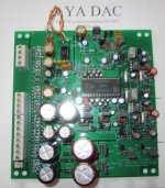
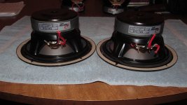
the smell from the trunk so we cut of the power removed it and I took it home. Curious if any damage can be visible, I looked
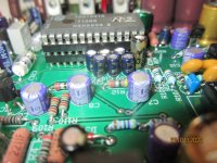
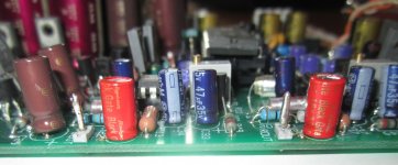
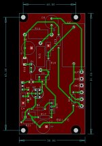
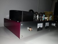
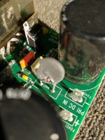
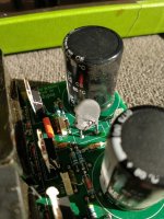
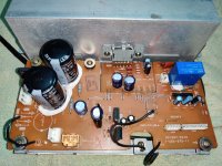
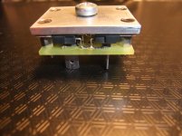
inside and noticed one resistor lifted up and the same one opposite burned on both ends. It's on first two pics:
.IMG_1588.jpg65461307474__6A7F1947-1788-470D-B10E-A35CD0031D26.jpg

Took it to audio repair expert and after few weeks he fixed it. Replaced the resistors and he got rid of the dust from the inside of the amp.
Back to my man who was doing the install. Couple hours later he called and said that this time it's toasted for real. Before the install I asked him
to check simply with 12v power supply in his workshop. We were able to play the music, green light was on and it switched off without problems.
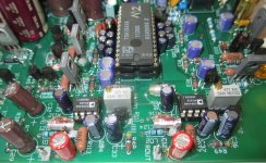
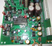
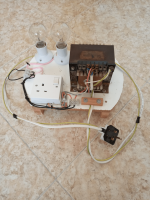
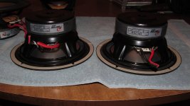
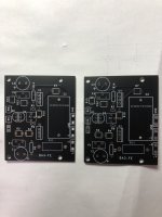
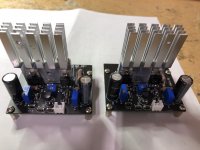
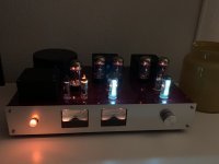
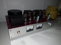
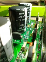
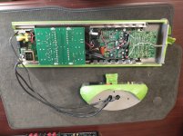
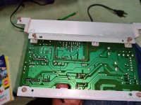
I looked inside again, the smell was really strong and it looked like charred bomb site. 2nd pair of pics:
IMG_1866.jpgIMG_1867.jpg

Took it again to the expert where he said that it looks like I have some issue with the ground wire. He mentioned that before at the first repair
and didn't even see the car......Now 3 months after I went there to see it and again the same resistors are replaced: ( now I know these are 10ohm
shield resistors).
IMG_2132.jpg

The guy at the repair shop , the expert I mentioned before said the amp turns on, green light is on but removing the remote wire
won't turn it off. It goes in protect mode with the red light. To save time and hopefully my amp as well, I told him I'll ask here on this group.
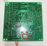
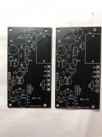
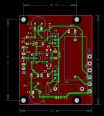
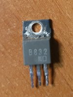
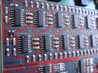
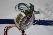
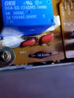
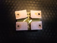
Now he tries to find out what are these parts for. I marked them with pink color. One is burned black so we cannot identify the values or whatever is
written on it. The second one where the numbers are clear theres no result when I search for it in the web. I've tried
with similar 8pin yellow color ones, just above those brown he removed. I see Korean network resistor but different values.

IMG_2133.jpg
Can you help identify that part? What can cause that amp to stay on after the remote switch off? What he can check or look for in this case? He
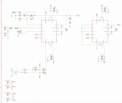
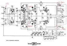
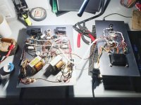
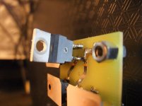
asked me for a schematic but I have only the manuals printed. Also he was right about the ground problem in my car, here's how the ground wire looked
like before I took all the old stuff out and replaced with heavy welding cables

IMG_1928.jpg

New project: modular speakers +sub (for stereo music)

Several years ago I made quite an investment in a DIY pair of fairly large 3-way speakers, based around Scanspeak 6" and 10" revelators and a tweeter in a Pellegrene waveguide. Then turbulent times hit and I suddenly found myself in a tiny flat, in which they could barely be stored - let alone used sensibly. However, I kept the drivers and am beginning to come up with a new plan for them:

The aim is to make things much more flexible this time, to account for wherever I'm living over the next several years or more. So the 6" and tweeters will form a pair of small sealed 2-ways that I can use almost anywhere in their own right. They will then be joined by either a new subwoofer, or else mounted on a pair of separate bass cabinets using the 10" drivers (to make them effectively 3-ways again). Should space etc permit at any point, then it could all be set up at once, as 3-ways+sub. I'm thinking active crossovers, that can be easily changed or switched-between to suit the different configurations.

TPA3116D2 breakout board

I wanted to play around with the 3116 and I couldn't find any TSSOP breakout boards, so I made one my own. I'm sharing the project if anyone wants to order boards themselves. There's not much to it except for some 1206 bypass caps.

Attachments

  • tpa3116_breakout_board.zip
    tpa3116_breakout_board.zip
    122.5 KB · Views: 93
  • tpa3116_breakout_board.png
    tpa3116_breakout_board.png
    177 KB · Views: 179
  • tpa3116_breakout_board2.png
    tpa3116_breakout_board2.png
    173.7 KB · Views: 161

Best Options for making F-5 an Integrated Amp

I am looking to build an F-5 to go with Markaudio 10P Pensil speakers, and I would like to make the F-5 into an integrated amplifier. My source is Mac Mini/Macbook Air through a Micromega MyDAC.

I have seen the build that includes the Mesmerize buffer preamp in the same chassis as an F-5, and I was wondering what other options/alternatives folks have successfully built or designed to make an Integrated Amp using the F-5 curicuit boards as the amplifier stage. I would be interested in both active or passive/bufffer options.

Thanks in advance for your time and consideration.

Dynaudio 17W75-XL and D28/2 Crossover and bass reflex help

Hi everyone,

i am in the middle of a project and i want some help with the crossover design and the bass reflex size. I have currently designed the enclosure for the speakers based on the dynaudios heritage special and the size of the contour 1.3 in which, i assume, the drivers came in from dynaudio.

The cabinet is 13.5 liters, subtracting the volume of the inside reinforcement piece and the speaker, and will be made from 20mm plywood. In the dynaudio dataset they have used a 15 liter enclosure with a 45mm x 80mm port for their measurements, should i use the same size port?

Regarding the crossover, i have found this thread and tested the referenced designs in Xsim, but i cant get a nice frequency response. I will attach the frd and zma files for the drivers. Can anyone help me with the design? I have uploaded a test based on the designs i have found on the thread.

Attachments

  • Speakers_dyn_2nd_side.jpg
    Speakers_dyn_2nd_side.jpg
    182.5 KB · Views: 2,427
  • Dynaudio.zip
    Dynaudio.zip
    24.2 KB · Views: 400
  • Dynaudio Foccus4 17W75XL D28-2.JPG
    Dynaudio Foccus4 17W75XL D28-2.JPG
    42.5 KB · Views: 1,589
  • Dynaudio Sirius 17W75.JPG
    Dynaudio Sirius 17W75.JPG
    42.8 KB · Views: 3,062
  • Screenshot.png
    Screenshot.png
    78.9 KB · Views: 1,444

Enclosure design for a Beyma 5" Coaxial (5CX200ND)

Hi folks ! Long time here.

I have two cute Beyma drivers that are staying too long in their boxes and decided that it was time to breath life into them.
Before putting all the data into WinISD, Basta! or Hornresp, I was just wondering if anyone had a good design recommendation for them. I'm open to any compact (or less compact) vented or closed design. I also have the 2 way filter for each driver

Beyma_5CX200Nd_N_(Photo).jpg
beyma-speakers-product-picture-filters-fd2cx.jpg


Resources :
http://www.loudspeakerdatabase.com/Beyma/5CX200Nd_Nhttps://www.beyma.com/speakers/Fichas_Tecnicas/beyma-altavoces-hoja-tecnica-coaxial-5CX200NdN.pdfCute cube design I liked: Login to view embedded media
Thanks for your help !

GlassWare Audio ACF Kit 12Vac buffer w/ JJ ECC99, poly caps and 1% metal film resistors NIB

SOLD SOLD SOLD SOLD SOLD SOLD SOLD SOLD SOSOLD SOLD LD

NIB GlassWare Audio 12 Vac buffer and x2 JJ ECC99 tubes, CDE 942 series 0.1uF & 1uF polypropylene capacitors, and 1% metal film resistors + User Guide.

Kit was $140. Asking $70 and $9 USPS Priority mail shipping to lower 48 USA only, please.

Dual EDS1000 and EDS1000-2 direct drive motor

Dear all,

I thought I share some experience with the the Dual DD motors from the 1000 series.
When the Dual CS 701 came to market I was lucky enough to be working for the Dutch Dual importer.

I have repaired there numerous Dual and Perpetum Ebners , PE was around that time acquired by Dual.
For me it was a great move when Dual finally stopped making record changers and moved on to single disc players.
The changers where good but required a lot of maintenance and adjustment.
One of their main problems was the main bearing that was hollow in order to control the record stack mechanism.

More rumble from this type of bearing was unavoidable.
So very happy Dual dropped that for the CS701 and CS601.

Later I looked at the other DD motors from Dual and had high hopes for the CS704 which I bought many years ago but it does not compare favorably to the EDS 1000`s.
Not so much in construction but more in torque.

My first Dual CS 701 was sold a very long time ago , it had served me very well with an EMT TDS15 glued into its head shell.

The early EDS 1000 motors where problematic because the platter would move up and down while running, this was very quickly corrected although I do believe some made it to the market.
There was also a problem with the hall sensors that would go bad.
Had to repair quite a few of those which was not easy to do as the whole motor has to come apart in order to do that.

The newer EDS 1000-2 never had those problems and featured silicium transistors instead of germanium.

Recently I thought to do some service on my EDS 1000-2 motor, mainly the electrolytic capacitors as I thought they would have been aged so they would need replacement.

However when I had three of them out and on the meter it turned out quite different.
They where all like new and perhaps even better than the new ones I had bought, quite shocking in fact.
I tested them for ESR, capacity and V loss.
I did replace them anyway but a good lesson was learned.

A few words on the bearings of the EDS 1000-2 I have I did try a few different oils like the thicker oil (Renotack I think) Dual used and later some van den Hul zirconium doped bearing oil but none made it run better.

Reflecting on this I believe the bearings which are sintered bronze don`t need lubrication unless they stick.

A final note, the Dual CS701 platter sounds better than the one from the CS721, it is quite a bit heavier.

Have a good Sunday you all, regards Veeren

F2 pcb group buy...

I'm opening this new thread as it seems like the offer for F2 boards has been lost within the original WTB inquiry.

The F2 amp board has a scoring line and is good for two channels.

Price for two channel pcb is USD$18, shipping included, paypal payment to my e-mail address posted here: http://audiosector.com/contact.asp

All boards will be shipped by airmail, with no tracking and no insurance and I cannot assume responsibility for lost packages. If you need insurance, please add $7 to your order.

The dual channel board is pictured below, output devices spacing is exactly as with F4, F5 and AJ pcbs, so the boards are interchangeable.

The matching power supply board available from this link: http://www.diyaudio.com/forums/showthread.php?t=149672

Attachments

  • F2.jpg
    F2.jpg
    193.4 KB · Views: 2,078

FS:ultimate attenuator kit for audio,balanced/single-end

This is a great KIT for those DIYers who want to build high-end quality audio DIY projects. It based on the following highlights:

R-2R current switching technology
High precision SMD resistors
High performance Analog switches DG413DY
Ultra-high performance Op-Amp AD797AR
Ultra-pure voltage regulator on board
Ultra-low noise
Ultra-low distortion
Low output impedance


Micro-controller with remote handset
4 input sources selectable

Wide range attenuation -96dB~0dB in 1dB/step

With this KIT, you can build a HI-END preamplifier easily ^_^

Price :
$250 single-end stereo
$450 balanced stereo
paypal accepted
airmail registered included

More information about my KITs ^_^
http://www.diyaudio.com/forums/swap-meet/135458-new-project-r-2r-attenuator-remote-control-v2.html

http://www.diyaudio.com/forums/swap-meet/144038-new-remote-volume-controller-10-sets.html

http://www.diyaudio.com/forums/swap-meet/130302-share-remote-volume-control-kit.html

attachment.php


attachment.php


attachment.php


USER MANUAL is ready, drop me an email ^_^
bbp6604560 at hotmail.com
orthoaudio at hotmail.com

thanks

Attachments

  • VOL ULTIMATE.jpg
    VOL ULTIMATE.jpg
    112.1 KB · Views: 4,485
  • VOL UL.jpg
    VOL UL.jpg
    98.2 KB · Views: 4,490
  • VOL U.jpg
    VOL U.jpg
    114.4 KB · Views: 2,844

My new 6v6 Tube Amp

Greetings from Germany!
Here I would like to present my DIY tube amp for home hifi.
All Analog. Free wiring, own designed housing (Housing createted by myself, made by good Friend for cheap money in Poland).
Amazing!
Greets!

martin.

Attachments

  • B9A053E7-C64E-47E4-9DA1-B00B3CE6A059.jpeg
    B9A053E7-C64E-47E4-9DA1-B00B3CE6A059.jpeg
    224.4 KB · Views: 178
  • 52AF1E26-2624-4B30-BFC2-9668B3A528C3.jpeg
    52AF1E26-2624-4B30-BFC2-9668B3A528C3.jpeg
    252.9 KB · Views: 177
  • CA59C668-C71A-4631-B741-C82EF591AA0B.jpeg
    CA59C668-C71A-4631-B741-C82EF591AA0B.jpeg
    231.2 KB · Views: 179
  • CA920AF6-F96D-43AE-8D10-CDDF54942295.jpeg
    CA920AF6-F96D-43AE-8D10-CDDF54942295.jpeg
    215.1 KB · Views: 165
  • F332379C-9208-4A8D-BD62-27524518C2BB.jpeg
    F332379C-9208-4A8D-BD62-27524518C2BB.jpeg
    231 KB · Views: 173

question about box for peavey woofers

Hello,

I have 2 peavey 15" woofers from PRO Sub MK II cabinets, is it worth to use thows elements to build something better than the original boxes, scoops, horns etc? or they are just to low spec drivers.

Just to explain why i would like to do somthing like this: i just have them laying around and now i have to sit home in quarantine with covid for 10 days so would be nice to construct something intresting + i love wood working projects 🙂

All the best

Turning a 6.3 V secondary into a 5 V secondary on an Antek 2T350

Folks,

I figured I'd share... Transformers are not exactly rocket science, but some people seem to be a little intimidated by them.

I have an Antek 2T350 that I intend to use for a project involving 5AR4 rectifiers. These rectifiers have a 5 V filament. The trafo provides 6.3 V. What to do...

Option #1: Insert a 0.68 ohm resistor in series with the 5AR4 filament. This drops 1.3 V across the resistor and voila, 5.0 V across the filament. However, it also dissipates about 2.5 W in the resistor which will need to be gotten rid of.

Option #2: Unwind the secondary a little bit to change the turns ratio from 120:6.3 to 120:5.

I opted for the latter on this project. I counted 21 turns on the secondary. So a little back of the envelope math:

6.3/21 = 0.3 V per turn
5/0.3 = 16.7 turns

So to get a 5.0 V winding, I'd have to make a 16.7 turn secondary. 17 turns aught to be close enough... So if I remove four turns from the existing secondary, the voltage should drop to 5 V (maybe slightly higher). So I set out to remove four turns...

It's quite straight forward. The tape end of the plastic film wrapped around the transformer is found and the tape is removed. Then the plastic film is carefully unwound enough to expose the secondary connections. Taking care not to nick the windings, an exacto/utility knife is used to cut back the adhesive tape wrapped around the core. Note how the ends of the two secondary windings are interleaved between a piece of card stock to ensure that they don't short out. Pay attention to the sequence of the wires. I removed two turns from each end of each winding. The turns are actually bunched up slightly at the termination point, so I could do this and still have the secondary evenly spaced across the circumference of the core. With the now 17-turn secondary, I measured the secondary voltage. I loaded the secondary with a 5AR4 rectifier for this measurement. At 115 V input, I measured 5.0 V. At 120 V, I measured 5.25 V. That's within the +/-10 % normally required for heater windings, so I decided to stop here.

The secondary wires were cut, the laquer scraped off with a knife (followed by an emory cloth polish), and the old secondary output wires were soldered on. Then the windings were secured with tape and the plastic film was wound back on.

The whole process took me about 90 minutes including photography. With the transformer completely assembled, the output voltage on the secondary was 5.2 V for 120 V input.

Pictures from the various stages of the process below.

~Tom

Attachments

  • Trafo-1.jpg
    Trafo-1.jpg
    455.6 KB · Views: 1,171
  • Trafo-2.jpg
    Trafo-2.jpg
    243 KB · Views: 1,068
  • Trafo-3.jpg
    Trafo-3.jpg
    439.8 KB · Views: 1,048
  • Trafo-4.jpg
    Trafo-4.jpg
    532.8 KB · Views: 1,117
  • Trafo-5.jpg
    Trafo-5.jpg
    501.8 KB · Views: 1,014

F5 w/- 32v rail questions

Hi,

I'm upping the rails on my F5 to 32V (600VA 24v transfo) and have read the F5 Turbo manual where it says I've to also consider increasing R9 through to R12 to 5 watt, I intend changing these.

I'm a little confused though. If I only up the rails to 32V and change R9 through R12 to 5 watt, will this configuration alone still be capable of driving loads down to 2 ohm without burping?

Whats throwing me is I've read elsewhere that a stock F5 wont burp driving loads down to 2ohm, but in the F5 Turbo manual it goes onto asking "Want to drive 4 ohms with this? You can do it, but I recommend that you consider the upgrade to the F5 Turbo V1". However, the V1 also has the limiters removed and an additional set of output devices.

So where do I stand with loads down to 2 ohm if I only increase the rails to 32V and change R9 through R12 to 5 watt please?

If your wondering why I'm going with a "600VA".. I'm planning further upgrades later but for now I prefer to stage things up to be sure heat with my enclosure sinks doesn't catch me out... I wanna play with bias along the way

Many Thanks

F.S. ATB PC PRO #2 Brand new. Cheap.

Good morning. After trying to install this program on my computer I see it is never going to work. Now I need a new computer so am selling the program. I bought the vibration sensor as well. I have everything it came with. I have not opened the microphone still in package and dvd and sound tone cd.This is a great deal and you can add on the PC Quality Test unit for further measurements of quality control and the rub and buzz test and more.
I bought from meniscus audio group (great guys to buy from). I can give you the original receipt. I paid $301.40. I will let it go for $250.00 and I will pay for shipping to the 48 United States. You can e mail me or pm me with any questions or concerns? Cheers Jeff

ProAc 100 Crossover tweak; Scan speak 18W/8542-00 and new 18W/8542-10 .frd and .zma files?

Hi All

I am looking to potentially tweak the crossover of my ProAc Studio 100s. Reason being the new SS 18W/8452-10 replacement drivers make the entire speaker sound too different to me. (Perhaps I am crazy.)

Apart from maybe just tweaking the series resistor on the tweeter slightly to rebalance the drivers (perhaps misguided). I was hoping someone might have or could lead me to the FRD and ZMA files for these two drivers so I could play around a little in X-Sim to see what tweaks might help make the speaker sound more familiar with the new replacement drivers.

Any help appreciated, I am 100% a n00b in these arenas.

Dan

Amplifier & dsp boards & speaker drivers sale

Hey Guys,

I have various DIY parts and projects for sale & can ship within UK some parts, the bigger stuff buyer collects.
Can post photo's if you are interested i specific items, PM's please.

Loudspeaker drivers:
4 (2 pairs), unused apart from TS parameter testing. Seas Excel 8 inch Mag coned,Seas Excel W22EX/001 - E0022 8" Magnesium Cone Woofer - Your favorite one-stop-shop for DIY audio components - SoundImports
18 (9 pairs) Beyma, 5.5 inch broad band new, unopened box's https://www.beyma.com/speakers/Fichas_Tecnicas/000009589.pdf
12 (6 pairs) 7 Inch Peerless bass mid, unopened OEM spec ??!!
24 (12 pairs) CSS 4 inch Neo motor BMR. Rare, normally only available to OEMs in high volume.... Some unused brand new, most in test cabinets. All perfect working order. http://www.cotswoldsoundsystems.com/specifications/CSS_Specification_Sheet_BMR85DDXE_N4R_r1.pdf

Manger drivers: 4 drivers (2 pairs working well plus 3 drivers good for spare parts. These are Exotic beasts .... PM for details, no time wasters please..These are £1,000 each(!) new so no silly offers!

Beyma full range 3 inch, 8 drivers, unused unopened box. (4 pairs) LOUDSPEAKER 3"FR30 8 OH
1 Focal 11 inch Kevlar (yellow) coned driver. 11K 7512 Focal 11k7512 11" Polykevlar Woofer

Electronics:
Lyngdorf TDAI 2170 plus HDMI board plus USB input board plus A to D board. Great condition with measurement mic and stand. Boxed. High end beast! https://hometheaterreview.com/lyngdorf-audio-tdai-2170-integrated-amplifier-reviewed/
DEQX with custom case and Lithium Ion battery power supply, USB input. https://www.deqx.com/products/hdp-4/
Spare DEQX boards with sub boards.
4 First One Amplifier modules with optional cap boards. Brand new, unused. Set for 48 volt DC input. ideal for battery project.
Spare 150 watt Class D per channel power amp.
Benchmark 4 channel DAC module. Not sure what model... Its never been out the bubble wrap!

These are great.... 4 unused AKM A to D chips, AK 5397 EQ. Mint!

Loudspeaker cabinets
4 cabinets (2 pairs) Acrylic open baffle. Rebated driver cut outs for twin 8 inch Seas drivers matching above).
2 (1 pair) 12 litre sealed box 18mm MDF cabinets, nice metallic grey paint finish. Check out these beauties! http://www.michaelvalentinestudio.com/hi_fi/hc2006hifishow/picture24.php

Whole bunch of cables /interconnects and Cardas speaker terminals and silver spades, 20 meters of silver 0.8mm solid core cable plus teflon sleeve.

Cheers
Alex.

Huge 2-way with 18" woofer and 2" exit compression driver?

I've been thinking about this for a while. Anyone ever do this? Could be used for personal home listening, parties, outdoors, DJing, small live gigs, etc.. a tough thing to pull off, but I'm wondering what the result would be like. I'm thinking one might end up with something that sounds very similar to the typical sound of a movie cinema, but perhaps sounding a lot bigger and better in the typical listening room, plus extra low-end from room gain and a better woofer/enclosure combo.

Also, I'm aware of the problems associated with a 2" exit compression driver running above 10 KHz, but I'm curious as to just how audible it'd really be. More than anything, I think the high directivity above 10 KHz and the resulting off-axis downward slope above 8-10 KHz as a result would be more problematic than anything. But I still wonder what it'd be like.

So, a single 18" serious pro sound woofer in a large vented enclosure with a 2" exit driver mated to a large pro sound horn, digitally crossed at 400-500 Hz, 8th order lowpass on the woofer and 4th order highpass on the compression driver.

For example, here are some of the specific components I've been eyeing:
Goldwood GM-450PB 2" High Frequency Horn
Peavey 18" Low Rider Subwoofer Speaker Driver
Peavey 18" Low Max Subwoofer Speaker Driver
Choice of compression driver is still very much up in the air.

Anyway, either of the above woofers would work well in 10^3 tuned to about 30 Hz, capable of 120-123 dB continuous @ 1m before Xmax starts coming into play. I'm curious though about the frequency response of these woofers, since Peavey never seems to list measurements. They state 500 Hz and 1 KHz, but I somehow doubt they're so limited. Inductance for both woofers is fairly low too, compared to other woofers in their class.

I've used these links below as a general idea of what to expect from such a 90 degree 2" exit horn and driver combo. These horns seem very similar to that cheap Goldwood I listed above:
http://prodance.cz/protokoly/RCF_H9040_DE750.pdf
http://prodance.cz/protokoly/fh2450_de750.pdf

Speaking of the Goldwood horn, P.Audio makes an identical one for a lot more money. I'd typically stay away and flat out ignore anything from Goldwood, but this 2" horn might turn out to be a really good value.

Anyway, just contemplating, and thought I'd inquire for any thoughts and experiences regarding such a project.

edit:
Also, my biggest issue with the above is the digital crossover, in regards to volume control. Is there still not a readily available volume control with XLR outputs for DCX2496 and the likes? Why the hell not??

how much added passive cooling Hypex UCD and SMPS needed?

Hi,

I've purchased 10 UCD400 OEM units which have a aluminium L bracket and a small (about 1cm high, 8x7cm) heatsink attached to it. 8 of those will be powered by one SMPS3KA400, another 2 in stereo by some chinese 600W smps.

20220126_122003.jpg


Furthermore 2 standard UCD2K units (they have some limited cooling on the board) powered by 1 SMPS3KA700 for my stereo subwoofers.

Looking at pictures from other builds, I seldomly see added heatsinks for cooling on SMPS or on UCD400 units. UCD2K builds are more rare, but passive or active cooling is used more often. Reading the specifications though, they do recommend cooling of the unit. I would like to use passive cooling instead of active due to the noise.

The use will be for a home theatre, not at reference levels, so not running 'full blast'

I am wondering about cooling as I'm ordering cases for them (modu) and am contemplating either using the Sepante or Dissipante line. The Sepante line is a lot bigger inside, which gives plenty of options to add some cooling. They also have an option to add a fully ventilated top cover, which the dissipante does not have.

I used this online tool to calculate:
https://celsiainc.com/resources/calculators/heat-sink-size-calculator/According to this, a heatsink should be 5 cm high (fins, 8x8cm) for the UCD400 if using 300W. For the UCD2K consuming 500W it should be 10x15x5 (high). Especially for the SMPS I'm not sure if extra passive cooling is required. I'm leaning towards adding only 1 heatsink to the UCD2K. I would think this is sufficient (can cut in 2, one for each UCD2K)

https://www.audiophonics.fr/en/kits...lack-anodized-300x125x50mm-black-p-10871.html
I wonder about cooling:

  • UCD400 uses much less power in idle, less than 10W, and is pretty efficient. Would the smallish heatsink be sufficient or should I add more cooling? I would put all of them on one L shaped aluminium bracket, so the heatsinks would be connected and thus 'shared'.
  • UCD2K uses more power in idle, 35W, so will get hotter even if not used. Would adding a heatsink be needed for subwoofer use?
  • SMPS3K power units: is the onboard cooling sufficient? They will be pushing quite some boards, 70-80W in idle and 2-3kw in full use all channels, though realistically in continuous use it will be about 1000W in normal use.
  • Case height. The UCD400 is only 8 cm high (on its side), so a 3U case has 12cm height and thus 4cm 'clearance'. The UCD2K is 11cm high on it's side, so only 1cm clearance in 3U case. Should I go to a 4U case and put it on it's side, or put it 'flat' and add a 'L' so I can add the heatsink on the side? The footprint in the case would be quite large in that case, 20x11cm (heatsink 5cm) compared to 14x9 if put on it's side (but higher!).

Thanks a lot!

Standards on wiring op-amps as gain stages?

I have a very basic understanding of op-amps and when I look at schematics I see less standardized usage of them than say a 12ax7 tube. Generally with a preamp tube, there's a plate resistor, a cathode resistor, a coupling cap, a grid resistor and cap on the input to block DC, and you see that everywhere.

Is there a similar "standard" way to wire an opamp as a gain stage (say while using the inverting input of the opamp as signal in and with a dual supply voltage for example)?

A Beginner's Guide to Barrel Connectors

I am trying to order a chassis for my AKSA-Lender pre-amplifier, and it looks like a Modushop 2U Pesante will have ample room. The pre-amplifier currently uses a 12V/1.5A wall wart, the business end is a 5.5mm x 2.5mm barrel connector. While I realize they can be polarizing (heh), since what I have is working well, I'd like to keep it.

We can find several different types of panel-mount barrel connectors. I understand the idea behind the threaded-body types (e.g. the PJ-064B); I've used them already for my MoFos. But I'm not that keen on the esthetics of them.

And so my question is about the other types, of which there seem to be at least two:
  • Sockets with 'wings' that look like they are meant to accept small screws (e.g. the PJ-039BH) Sometimes the screw sockets are 'inside' and sometimes they are 'outside'
    CUI-PJ-039BH.jpg
  • Sockets with 'grooves' that look perhaps like they are meant to be slid into an opening cut from the edge of a panel (e.g. the PJ-009BH, or the PJ-008B)
    CUI-Devices-PJ-009BH.jpg

Can anyone describe to me how these are attached to a panel? CUI has not deigned to answer my question from several days ago.

Kind regards,
Drew

Looking for Replacements For Unavailable Parts in Millet Nuhybrid BOM

I'm planning out a build of Pete Millet's NuHybrid HA. I've ordered the PCB and truly appreciate the comprehensive build instructions.

The BOM from Mouser has a few components that are out of stock that I dont trust myself to find replacements:
Then there are few marked 'obsolete':
If anyone has any tips on replacements, I'd love the help. Otherwise Ill start from the top down listing what I can find to replace these.

Cheers

Surgistor on a subwoofer amp - is it blown?

I have a fairly high end Infinity Prelude MTS powered subwoofer that suddenly stopped producing any sound. I confirmed that it is getting power and sound signal (RCA connection) - it even "wakes up" from stand by but still emits no sound.

This sub is a BASH amp but it does use high end transistors and is supposedly 850+ watts.

No authorized dealer will work on these anymore and parts are no longer available.

I took the amp out just to take a look see and I found this - see pics.

I have the service manual and they call it a "Surgistor" 4R 8A 70JSL154R008. It is located on the main power supply board (with the big caps) and it is directly next to the DC IN leads.

It looks bad and pitted but does it look like it failed? Do you think this could be the cause of the issue?

I might be able to fix this myself if I can find the surgistor somewhere. EDIT: I found the part. Digikey calls it a current inrush limiter and Mouser calls it a thermister so I guess it is a sort of surge protection.

Thanks for any suggestions and help.

Will

Attachments

  • IMG_20220126_095242898.jpg
    IMG_20220126_095242898.jpg
    150.6 KB · Views: 230
  • IMG_20220126_095330587.jpg
    IMG_20220126_095330587.jpg
    125.9 KB · Views: 203
  • IMG_20220122_094935156.jpg
    IMG_20220122_094935156.jpg
    270.6 KB · Views: 164
  • IMG_20220126_095229859.jpg
    IMG_20220126_095229859.jpg
    151.9 KB · Views: 212

JL 1000/1 Low Output Issue

Hello,

I am having an issue with my Jl 1000/1.

The amp has very low output.

With a 2.5Vrms signal in I get ~6Vrms out (At max gain).

There is no distortion just very low output.

Idle current is ~2.8A and there are no error lights on the amp. It starts up normally with only the green light illuminated.

I've cleaned all of the pre amp switches and removed the preamp board to reseat. Neither seems to help this problem.

Any help would be greatly appreciated.

Thanks,
Steve

Fresh EL84 integrated SET build - gain issues...

Hi.

I bought a Heathkit SA-3 integrated amp about a year ago, and after doing a rebuild - new caps/resistors - couldn't get it to work.

So, I tore it down completely, made a new "enclosure" and built a new amp from the "bits"

Powered it up safely, and no blue smoke or magic sparkles.

Sounds very nice with a couple of caveats...

The Volume knob is insanely sensitive. Reaches full volume at about 8/9 o'clock, and if it gets dialled up further, there is no change in volume. It also starts to distort quite a bit before it reaches max volume - gets grainy and "scuzzy" (Max volume is not very loud). Granted, I realize this is a flea watt amp, but I'm running it into 90db speakers and feel it should be louder overall?

I removed both the treble (C10 & C11/R13 & R14) and bass control (C17 & C18/R29 & R30) as I didn't want them and wondering if this might have something to do with it?

Also, there is a small cap (C1 & C2) as well as a resistor (R1 and R2) on the RCA inputs. Wondering what they do? Are they a filter of some sort?

Thank you!

Per

Attachments

  • SA-3_Schematic_Master_Copy.jpg
    SA-3_Schematic_Master_Copy.jpg
    334.7 KB · Views: 190
  • image0.jpeg
    image0.jpeg
    576.7 KB · Views: 192

UPL with Option B1 - Enabling Cuts Audio Output

I've just purchased a second UPL, this one with the Low Dist Gen option (3 years searching for one!) and am in the process of checking it out. Seller is ATE Test Equip.

I noticed there is no output from the generator unless I turn off the Low Dist option.

Is there something else that must be set up for this to work? I'm testing with the THD setup. The normal (non Low Dist Gen) seems to work, although the Ch1 voltage level reading is not 1.000V as with Ch2 (both are 1.000V on my other UPL). Maybe the calibration is off, too.

Anyway, just wondering if something's wrong with this unit.

Help needed for fixing a Mark Levinson No 38 (one channel is not operating anymore)

Dear all,

I am new on this forum but i still hope somebody can help me getting the Mark Levinson No 38 pre-amplifier fixed. On the internet i do see some schematics but they are too low resolution to read the nbrs. Furthermore i do not see the supply voltage schematic from where i would like to start trouble shooting. Can somebody help me?

Kind regards

Foxx71

Unknown TO220 Diodes (discrete Bridge Rectifier) for Horch 3.0S and Threshold 4000

Unknown TO220 Diodes (fast recovery Bridge Rectifier)f. Horch 3.0S and Threshold 4000

Usual 50/60 Hz bridge rectifier are versions like this series:
https://www.farnell.com/datasheets/2864019.pdf

Such versions are sometimes replaced by discrete bridge rectifier versions consist of 4 pcs. single diodes in TO220 outline for getting ultra fast switching character and/or ultra fast recovery behavior - go to URL's as follow for various examples:
https://unitedsic.com/datasheets/DS_UJ3D06530TS.pdf
https://www.st.com/resource/en/datasheet/stth12r06.pdf
STTH12R06 - 600 V, 12 A Turbo 2 Ultrafast Diode - STMicroelectronics
https://www.mouser.de/datasheet/2/427/VISH_S_A0003169751_1-2568737.pdf

The one from the attached images are mounted in a power amplifier from the German brand Horch, model "3.0S"
http://www.horch-gmbh.de/Produkte/HORCH 3.0 S.pdf
also suited for replace the usual rectifier (like to find under the first URL) in the cheaper Horch model "3.0"
http://www.horch-gmbh.de/Produkte/HORCH 3.0v.1.pdf

No additional snubber parts like to see under
https://web.archive.org/web/2010040...oltSecond/Rectify_1/rectifiers_and_xfmrs.html
were used

Maybe one diode is flawed - consequence was an extremely loud hum of one of both toroidal transformer (by measuring with diode tester no abnormalities are to observe - i. e. not shorted and no interruption).
The used capacitors are big cans with 33.000uF and 80VDC from FT cap.

Unfortunately the type designation of all diodes from TO220 surface was removed by grinding - thus the question rises up, what should I use for the right replacement.

I filed the topic here because the same problem also occurred with the Threshold 4000 vintage power amplifier (the usual 50/60Hz rectifier - go to
https://pdf1.alldatasheet.com/datasheet-pdf/view/1099761/NJSEMI/MDA3502.html
where was also replaced the mentioned rectifier by four pieces of fast diodes in the TO220 outline - also without additional snubber parts) - type designation from TO220 surface was here also removed by grinding from the repair guys who made this modification at least 20 years ago.
I. e. I have here the same problem to choice the right replacement.

Therefore the question: what diodes should I prefer therefore and for high power amplifiers in general ?

Thank you very much for your information

This threads don't provide the wanted hints.
Reduced diode switching by placing a cap across
Standard Silicon Diode Rectifier's VS Ultra Fast
Suggestions for Ultrafast Diode.
Fast recovery diodes
Suggestions pro/con three different fast diodes
https://linearaudio.net/article-detail/2242
Fast Recovery rectifier diodes
schottky vs. soft/fast recovery diodes
fast vs. slow rectifiers

Attachments

  • horch3.0S-1.jpg
    horch3.0S-1.jpg
    548.4 KB · Views: 302
  • horch3.0S-3.jpg
    horch3.0S-3.jpg
    146 KB · Views: 273
  • Threshold model-4000 open.jpg
    Threshold model-4000 open.jpg
    53.8 KB · Views: 319
  • Horch 3.0S Capacitors.jpg
    Horch 3.0S Capacitors.jpg
    1 MB · Views: 311
  • Horch 3.0S bridge rectifier ultrafast-II.jpg
    Horch 3.0S bridge rectifier ultrafast-II.jpg
    870.3 KB · Views: 304
  • Horch 3.0S bridge rectifier ultrafast-I.jpg
    Horch 3.0S bridge rectifier ultrafast-I.jpg
    984.3 KB · Views: 264
  • Horch 3.0S bridge rectifier ultrafast-III.jpg
    Horch 3.0S bridge rectifier ultrafast-III.jpg
    980.1 KB · Views: 309
  • Horch 3.0S bridge rectifier ultrafast-IV.jpg
    Horch 3.0S bridge rectifier ultrafast-IV.jpg
    979.2 KB · Views: 311
  • Horch 3.0S bridge rectifier ultrafast-V.jpg
    Horch 3.0S bridge rectifier ultrafast-V.jpg
    979.6 KB · Views: 287

Help identifying EL156 Tubes

Hello! I recently ordered some Telefunken EL156 tubes from a supposedly reputable dealer, and received these unmarked 10-pin (y10a) tubes. They apparently are EL156’s, and to my knowledge the Chinese versions all have an octal sockets.. but I’m not convinced they are Telefunken or Siemens as the dealer claims. I’m hoping someone here can help me identify them. I would have taken more pictures, but there really isn’t much to see. There are no identifying marks whatsoever.
7740FB6C-99EC-447B-BD0A-51E0670FC660.jpeg

Has anyone built an amp using the 3E audio TPA3255 board(s) and their DSP board?

I'm on a slow pace, multi year hobby project to make a combination of 3-way speakers without analog crossovers, and class D amps with DSP to power them and do the crossovers / filtering.

I started out ordering a 3x200W T-amp board:

Sure Electronics AA-AB35281 3x200W Class D Audio Amplifier Board - T-Amp

And a lowcost DSP:

Dayton Audio DSPB-K DSP Kernel Board and DSPB-KE Kernel DSP Expansion 2-In 3-Out


For what it's worth, I'm powering them with relatively expensive SMPS board:

SMPS600RS | Connex Electronic


But I found out this amp board is pretty noisy, and when connecting the DSP board the noise is increased significantly...
IMHO, these parts *might* be usable for a boombox, but not for a home hifi setup.

To be fair, I've been warned on this forum about using these parts, so I'll add this to my "learning experience" list 🙂


So now I'm looking into getting better quality parts, and I keep reading good stuff about 3E Audio boards (on diyaudio.com for example).

Has anybody here ever put together an amp using 3E's DSP and amp boards?
Projects by fanatics, for fanatics
Get answers and advice for everyone wanting to learn the art of audio.
Join the Community
507,765
Members
7,887,489
Messages

Filter

Forum Statistics

Threads
406,178
Messages
7,887,489
Members
507,765
Latest member
aleminx