Question about 4" BMR drivers like used in Philharmonic's BMR kit... (F.E. Tectonic, or Cotswold Audio)

Since I first read about BMR drivers I found the idea quite interesting.
Once I found out about f.e. NAIM using them and the Philharmonic BMR speakers I decided I wanted to try them.

But - besides having built 3 or 4 designs by other people, I have zero knowledge about speaker design, I know diddly squat about electronics - I'm a software guy, not a hardware / electronics guy...

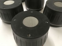
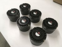
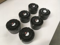
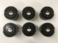
So anyway, I ordered a pair of Tectonic TEBM46C20N-4B BMR 3" Full-Range drivers (because I think that's what the Philharmonic BMR's use?).
I'm testing them right now in a test-cabinet together with a woofer and a tweeter.

They sound good - I like their dispersion, good sound off-axis.
But - when disconnecting the woofer and the tweeter, and turning up the volume a bit, to me it really does sound like overdriven (distorted) sound from a boombox.
I mean, it's a 3" driver so what can you expect, right?
But on the other hand I see very expensive speakers / speaker kits using these drivers - or drivers like these - and getting amazing reviews (like the Philharmonic BMR).
I know it's not them, it's me - I'm just starting out with audio stuff so what do I know.

But can anyone explain to me how for example the Philharmonic BMR speaker either gets great reviews while the mid-range driver (the small BMR) distorts so much when turning up the volume... OR how they avoid the mid-range (BMR) driver distorting somehow when turning up the volume?

(I'm not talking about club-level volume, I'mt talking about "birthday party" volume.. just slightly more than "usual living room volume" 🙂)

An idiot's blog to design and build speakers

This is the start of my blog documenting my (lack of) progress building a set of speakers from the ground up.

I am writing this here mostly for myself, and maybe other starters can learn from my (probably numerous) mistakes.

First: my background.
I am not completely new to speaker building.
I started a few years back, and I listened to the advice of the smart people in this game :
don't start off wanting to design your own 3-way speakers, start by building existing kits designed by people who *do* know what they're doing.

So for my first project, I built a pair of Needles:
https://www.diyaudio.com/forums/full-range/65061-range-speaker-photo-gallery-369.html#post4933327

Then I got the taste of it, and wanted to go bigger.
So I built a pair of Heissmann Acoustics "Samuel HQ"'s.

And while I was at it, I built my own class D amplifier based on the TPA3116D2, applying all mods mentioned in the diyaudio.com TPA3116D2 topic.

My audio family in one photo:
https://i.imgur.com/nglynTp.jpg

The Samuels were placed in my kitchen, which is 5x6m, and were placed in the corners because well, we have to be able to walk around in the kitchen, right?

This made them sound less than awesome.
Then by pure chance I was gifted a Umik1 by a friend.
I started doing measurements using REW, and found out that using PEQ I could get my Samuel HQ's to sound much better in my less than optimal listening space / kitchen.

(I use a Raspberry Pi with Hifiberry Dac DSP+ to perform the final PEQ)

So then - everything is fine and good...

But now I've been infected... and I want to *design* my own speakers!
So I've been reading on this forum and others, and the more I read, the more I realize I don't know about... well, *stuff*.

At every single point in time where I think "all right, now I know what's going on - I'm ready to start designing my own speaker", I read one more post just to realize "****, back to the drawing board".

This has been going on for a year or so, and I have now reached the point where I say : **** IT.

I'm not going to spend more years reading up on things while always being behind the times.,

I am going to put something together.
I am going to buy parts.
I will be told I've bought the wrong parts, I will be told I'm taking the wrong approach, I will be told it's not going to work..

..and that's fine with me 🙂

I will learn as I go along, but at least I have a starting point now 🙂

SO - my starting points are:
- I have decided I like the idea of full range drivers - no crossovers in the vocal range.
- I do like a little bit of bass
- DSP is awesome - I don't know **** about analog crossovers, DSP is my magic bullet for crossovers, room-correction and everything else


Thus I have now decided to just buy some drivers and make **** work. And if it doesn't work out, it's a learning experience.

The drivers I am going to work with are:

- HiVi RT1C-A tweeters
- Tectonic TEBM46C20N-4B (BMR) for full range
- Tang Band W6-1139SIF for (Sub) bass

My current idea is to use the Tectonics for the full vocal range - crossover for (sub)bass between 200 and 300Hz, crossover for the Tweeter between 4Khz and 8Khz, testing as I go along.
I will use class D amplifiers to actively power them (TPA3116 or better).
I will use a Sure / Wondom DSP board (ADAU1701) and SigmaStudio for crossovers and PEQ to match room measurements.

Once I get my first order from Parts Express this blog will continue.

WTB WTB: IXYS 10M90S few pieces

If someone had few extra IXYS 10M90S in TO-220 cases, they would be willing to sell, I would be very grateful. I just missed out on buying the last stock from Mouser amd Digikey and the next expected delivery date seems to be well into 2023. I have couple projects otherwise ready, just missing these few components. I would really like to finish them ASAP and I don’t want to try to buy the takes on eBay and Aliexpress.
edit: also looking for ADP151 2.5V tsop-5 voltage regulator too, it is out of stock too.

Heater resistance as FET source load

The contents of this post may make a few tube lovers cringe but I felt this was the best section to post for the information I seek.

I want to build a simple source follower headphone amp using a Sic JFET. This one to be exact https://www.mouser.com/ProductDetail/UnitedSiC/UJ3N065080K3S?qs=byeeYqUIh0OYOU7Cis0jMg== . Simulating this part with a 24V supply and a 42 ohm resistor as source load puts the source at 11.48V(roughly half the supply) for a bias current of 273ma. That resistor would have to dissipate a little over 3 watts. Now I could use a nice fat 10W resistor and be done. But what if I took a page from Pete Millett's Starving Student and used a tube's heaters as the source load. I have 15-20 used pull 12ax7 and -au7's lying around and no plans to use them for anything, so why not. I don't have to spend any money on 10W resistors and I'll have a little glow for late night listening 😛. Now if I use two tubes per channel in series with the individual tubes wired for 6.3V, I should end up with 12.6V / .6ma = 42 ohms. Which leads me to my question, will the FET see 12.6V on its source because that's what the tubes are designed to draw or will the source voltage be dictated by the resistance of the heater string(42 ohms)?

Side note:
1. To be clear the tubes will serve no other purpose than to provide a source load for the FET

2. I understand at 11.48V, I would be starving the heaters therefore reducing tube life. I plan on using 50+ year old used pulls of commonly available tubes so I don't think anybody should lose sleep over that fact. I won't.

Modelling PPSl horn in HR

So I've been attempting to model a PPSL cab with a short horn/waveguide slapped on the front.

I simmed the drivers in offset driver (OD) mode and created the plenum in S1 and S2.

The problem is that there is a large peak in the upper range of the cabs bandwidth which maxes out around 100Hz (ideally i'd like to get decent response up to 70-80Hz).

From what I have read the OD driver arrangement in HR would be both the drivers facing each other creating a standing wave?

Am I perceiving this problem correctly or is there something else at play?

Any suggestions for how I can deal with the upper range would be much appreciated.

Also any general suggestions would be valued also.

Attachments

  • ppsl.jpg
    ppsl.jpg
    147.6 KB · Views: 126

MOD DIY Wave Spring Reverb Kit question

Hi there. I've been building a DIY MOD Wave Spring Reverb kit for a few weeks. I got right to the finish line (almost) but I'm having problems with feedback when turning the reverb level up past 1 or 2. Something is definitely wrong and it appears that DIY MOD have stopped offering tech support on their kit builds due to it being too time consuming. I was thinking maybe someone here might have some suggestions? Perhaps someone else has built this kit and may have gone through similar troubleshooting? I've built a few pedal kits but this is my first full power build. I'm pretty new at this and have been very careful to solder the components into the right places. But, I'm pretty sure I did something wrong.

One thing also that has been perplexing is that the input to the reverb tank shows continuity between the sleeve and center. I asked the MOD DIY folks about it and they said it may read 1.8 ohms on my meter. I'm reading about 1.0 ohms. So not sure if this is the issue?

Any thoughts? Hopefully this is the correct forum to ask this question. Thanks so much!

Glass Diodes markings and values help

I am repairing a Massive Nano N2 800.1 monoblock amp, seems to be just 2 IRF640N that went bad, it powers up good, no more protect, on 12v2a out of heat sink but was only drawing maybe .6a and had a pretty loud buzzing, I still need to do more testing and put my scope on it but when measuring the glass diode at D35 only measured .06v while the above at D37 measured .6v, which from some reading is nominal? Is the diode at D35 off spec, maybe connected to the circuit with the removed blown mosfets, and that being the reason why it’s off spec? Any help with these glass diodes is greatly appreciated, I’m off to read more and try to find more info, thx and take care all!

Below is close up pic of D35 & D37 and their distance from the output mosfets, I’m assuming they are somehow connected, I’m still learning class D topology 😅

Attachments

  • 85EFB3E2-D445-43EF-A753-255A37B4FFAA.jpeg
    85EFB3E2-D445-43EF-A753-255A37B4FFAA.jpeg
    403.2 KB · Views: 328
  • 3610D2D5-2A10-4089-9F95-6D817B48AA91.jpeg
    3610D2D5-2A10-4089-9F95-6D817B48AA91.jpeg
    462.6 KB · Views: 277

Elac DS-S101-G Discovery issues

Hi, I tried this device out just to get to know Roon Essentials and discovered to my surprise that it plays 24/96 and 24/192 content as 24/48. Via coax SPDIF that is. The Toslink output gives such bad results it should not even be considered to be able to compete with the coax output.

It seems, unbelievable as it is, that no one noticed this as I read quite a few reviews (FWIW...as we can see reviews are best avoided). Elac was not so keen on giving support, even reluctant to acknowledge this phenomenon and trying to divert attention to the external DAC (which does not make a difference of course) and the material itself being the culprit. So, a little disappointed I sent the device back while it was still possible. I would have liked to find out the exact cause as the hardware seems capable of playing back 24/192.

I found Roon Essentials to be the best software I have used till now and in this version the most optimal as all the necessary stuff is concentrated on 1 device which is the Discovery. The subscription model and high price of the original Roon won't work for me but the Roon Essentials version cuts the cake. The confusing playback of high res material however was enough for me to stop testing. Does this ring a bell? It does play the material but always as 24/48 as it seems. A hard reset and doing all updates does not make a difference. The device I tested was an early 2016/2017 version sold in 2020. Mainboard revision F, internal OS version 1.3, Roon Essentials version 1.7.

KRK VXT6 Powered monitor

Hi, all DIYers,

I have a Krk vxt6 monitor which has a shorted transformer. I can get a new transformer from a company called Toroidy. I was just wondering can these plugs be taken off the old transformer and put on the new one. I don't even know what they are called. If anyone can help that would be great.

Thanks
Keith

Attachments

  • 20220205_174229.jpg
    20220205_174229.jpg
    190.7 KB · Views: 91

Step by step instruction on how to build tpa 3251/3255 module amps? I would love a 6 channel if possible

Hello everyone,

I'm pretty new to all of this and very new to the group. I have built a few pre designed crossovers, and successfully opened up my Vmount battery adapter to re-solder some leads on a power button so it works again. That's it. No other electrical experience.

Are there step by step instructions/kits on how to build a 6 channel Class D amp where someone with enough patience and time could successfully, and more importantly SAFELY build one of these amps? Thanks in advance!

Old valve radio electrolytic capacitor

I don't know if I'm in the right section, however I have an old Telefunken Domino that I'm trying to get my hands on. The main electrolytic filter caps may need to be replaced (actually I realized that the one connected to the rectifier valve has already been changed by a previous repairer).
I was wondering which ground connection is relative to the one encapsulated in the aluminum shield, is it the case itself? It is a 50+50uF. Thanks in advance

Attachments

  • MG_2650 - Copia.jpg
    MG_2650 - Copia.jpg
    107.1 KB · Views: 262
  • R172-2-TFK-Domino-R172.png
    R172-2-TFK-Domino-R172.png
    20.8 KB · Views: 256

Altec Lansing in immaculate condition

I found these photos on the web and wanted to share them.
By the way, there should be a new category: Coaxial-Triaxial
Although they can be considered multi-way, they are "all in one" transducers (on the same axis), not separately.

Enjoy !

Attachments

  • 3_9bdc49cd-fe7a-4467-afcf-6e05a2caf1b3_960x1280.jpg
    3_9bdc49cd-fe7a-4467-afcf-6e05a2caf1b3_960x1280.jpg
    101.1 KB · Views: 155
  • 8_607ceba9-3db4-4f09-835d-c43cce0fc7fc_1280x960.jpg
    8_607ceba9-3db4-4f09-835d-c43cce0fc7fc_1280x960.jpg
    195 KB · Views: 143
  • 7_34aa1c10-4e5c-47a9-b166-c39701f568a9_960x1280.jpg
    7_34aa1c10-4e5c-47a9-b166-c39701f568a9_960x1280.jpg
    275.2 KB · Views: 136
  • 5_38f9c56b-9c3d-4e33-8d08-fb033025da08_1280x960.jpg
    5_38f9c56b-9c3d-4e33-8d08-fb033025da08_1280x960.jpg
    220.2 KB · Views: 137
  • 9_644430a8-3834-408e-a845-f8232dd14520_1280x960.jpg
    9_644430a8-3834-408e-a845-f8232dd14520_1280x960.jpg
    221.9 KB · Views: 143
  • 2_11045d59-2388-4845-b502-43bf1b0c2927_1280x960.jpg
    2_11045d59-2388-4845-b502-43bf1b0c2927_1280x960.jpg
    99.9 KB · Views: 145
  • 1_d26fc538-51c6-4a68-931a-0fd0e27c44b3_1280x960.jpg
    1_d26fc538-51c6-4a68-931a-0fd0e27c44b3_1280x960.jpg
    145.2 KB · Views: 138
  • 11_215ac6b6-1346-4211-b668-feb4be1d1791_1280x960.jpg
    11_215ac6b6-1346-4211-b668-feb4be1d1791_1280x960.jpg
    100 KB · Views: 165
  • 4_5c3c1f66-24fa-4aa9-a100-e787a8cd1900_1280x960.jpg
    4_5c3c1f66-24fa-4aa9-a100-e787a8cd1900_1280x960.jpg
    96.8 KB · Views: 153
  • 6_5a807c8c-a031-4cb7-bbf2-3f276885d729_1280x960.jpg
    6_5a807c8c-a031-4cb7-bbf2-3f276885d729_1280x960.jpg
    103.7 KB · Views: 134
  • 10_20de1ec2-f34e-4fd7-ba88-a848218f61bc_600x.jpg
    10_20de1ec2-f34e-4fd7-ba88-a848218f61bc_600x.jpg
    78.7 KB · Views: 158
  • Thank You
  • Like
Reactions: jrh0516 and GM

Need help identifying these Different, non-typical looking XLR interconnects, Anyone know who made these ???

Hey DIY, I could use some help identifying the maker of these XLR interconnects, have had them for a while and forget who made them; there's no name on them. Do any of you know?

XLR's with a flat, thin & wide conductor (I think) and a small ground wire (I think) running inside a nice linen cover. Made with some nice details: carbon fiber tubing and hardwood oak caps. Maybe similar to Mapleshade cables, love to find out who manufactured them? I remember back in the day where they were by Stereophile or Absolute Sound but it was ages ago.

Thanks in advance for any help.

51870120948_ea3728614a_b.jpg


51870037141_bb1d66ec15_b.jpg


51870120738_9b0e70038b_b.jpg


51869075567_8a5cecbec6_b.jpg

Common mode chokes and regulators

I have a question about running an lm317 supply with a common mode choke upstream.

Scenario A would have the choke between the secondary of the transformer and the diodes

Scenario B has the choke after the diodes before the 1st smoothing cap basically forming an LC filter.

The diodes are double rectifier type.

Which secneario is more benefitial and does the psu impedence seen by the 317 change between scenario A and B?

Hello

Hi there. I’m new to this forum but have some diy experience. I’m looking forward to learning and building new projects with the assistance of this forum.

For background, I’ve build:

Elekit TU-879S - great little tube amp kit that I bought from Victor maybe 8 or so years ago. It’s still working great!

Parts Express - executive kit. I bought this and built it with my teenager son over the holidays.

The PE flat pack concept got me excited and am thinking about venturing into speaker builds that way.

I have the silver preamp korg nu tube purchased just waiting for it to arrive….

Im excited to be part of the community and looking forward to learning and future projects.

thanks
Mark

LM4562 substitute in Doug Self's EQ

Hi,

I'm working on a compact SMD based PCB/build for Doug Self's EQ from LinearAudio#5.
It seems like LM4562 in SOIC-8 package is rather unobtainable at the moment so I'm thinking about suitable alternatives.
One guess that one choice that comes to mind is OPA1612. It should be of simmilar if not better overall quality except for the fact that it does not like loads below 2k where the LM4562 deals fine with loads down to 600R. Looking at the circuit, I don't think that is going to be an issue. I think the lowest load that one of the devices sees is A4b's output that sees 910R (R26)+ 5k (HF pot RV4) to ground. Should be no problem for the OPA1612. I may be overlooking something so it would be great if someone could offer a second opinion.
I'd also be interested in other alternatives. The OPA1612 isn't cheap and the circuit requires 13 of these guys so using ~$8 devices instead of ~$2 devices is a bit anoying...

Cheers!
Lars

Toshiba TA8233H Fully Built Chip Amp

Toshiba TA8233H fully built chip amp 30wpc BTL stereo

Designed & built by polish enthusiast Fryderyk Wrobel (FRD1996) based on Toshiba datasheet circuit diagram compete with generous heatsinking & all cables soldered into the board for power, input & output and including a pair of russian military matched output capacitors (see detailed pix)

The TA8233H was originally supplied to the automobile market and it will run on any DC PSU in the range of 9-18 vdc including of course 12v car battery

The TA8233H chip amp is highly regarded especially in Polish hi-fi circles and this is a great simple well-designed board, for anyone who wants to give it a go. only used once to test it working. part of a larger project that never came to pass

These chips are now somewhat difficult to find new (as this one is) with most pulled from used equipment

Looking for £40

Would prefer to post only to UK. Royal Mail 2nd class small parcel cost of £3, but pleased to use more secure service for royal mail cost

Thanks

Attachments

  • 20220127_141602.jpg
    20220127_141602.jpg
    284.3 KB · Views: 471
  • 20220127_141719.jpg
    20220127_141719.jpg
    328.8 KB · Views: 767
  • 20220127_141833.jpg
    20220127_141833.jpg
    314.3 KB · Views: 441
  • 20220127_141843.jpg
    20220127_141843.jpg
    120.2 KB · Views: 374
  • 20220127_141843.jpg
    20220127_141843.jpg
    120.2 KB · Views: 333

NAD C320 BEE problem - very low audio output

I have acquired a NAD C320 BEE amp which I believe suffered a period of running on low impedance speakers due to someone trying to run too many speakers in parallel. The C320 seems to work perfectly well on all functions and although the output is very weak on both channels, there doesn't seem to be any distortion. I've checked the pre-amp by taking out the links and checking output with a scope , and fed the power amp section with a tone generator - still the same results, low power. It's almost as if there is a mute or a protection circuit engaged. Both of my speakers and cables work perfectly by the way. And ideas folks?

Using DC Servo circuit in LM 3886 , but which is the better choice ?? Help and expirience need

Hi ,
for learning and testing i make a "Play" PCB with all I found around the Amp Topics.
One Part is the DC Servo.
I found two ways to realise them.
Each of them says it was the better 🙂
Buit wat was your expiriences ?
What is better A or B. ... I ask about the 2 Diodes 🙂

You see in simple block draft as Picture... So only about the 2 varinats of connecting DIodes.
Of Course has a block picture not all in it

Kind regards Michaela

Attachments

Wtb harman kardon citation v output transformer

Hi title says it all. I'm looking for a harman kardon citation v output transformer. I know - needle in a haystack - but figured I'd check. Otherwise if anyone is interested in buying a citation v with a bad transformer send me a pm. I'm going to sell this off if I can't find anything. It worked perfectly until a jbl 2220 woofer went open circuit because of loose terminals on the basket and blew the left output.

Thanks.

Diodes Incorporated PAM 8302A Mono Amp

I'm building a small mono tabletop radio. I'm thinking about using the PAM 8302A by Diodes Incorporated. It's a class D amp chip that can output 2-2.5 W into 4 ohms when using a 5 V power supply. Has anyone used this chip for audio projects?

I've attached the datasheet along with a couple schematics. One is from an Adafruit board and the other is a draft of my schematic. I'm fairly new to DIY audio and I still have a lot to learn. Here are some questions I have:

  • I'm using 1 uF ceramic caps with 100 ohm resistors for the inputs. Is there a better option for getting the best sound quality? should I use a different type of caps?
  • I have ferrite beads (600 Ohm @ 100 MHz) and caps (220 pF ceramic) on the outputs to reduce EMI. What should I do to get the best sound quality? is a low pass filter better?
  • I have two power supply decoupling/bypass caps (0.1 uF ceramic and 470 uF electrolytic) with the idea that they would filter both high and low frequency noise and the electrolytic cap would improve low frequency response. Are there better options?

Thanks!

Attachments

  • PAM8302A Datasheet.pdf
    PAM8302A Datasheet.pdf
    1 MB · Views: 138
  • Screen Shot 2022-02-09 at 4.36.26 PM.png
    Screen Shot 2022-02-09 at 4.36.26 PM.png
    11.5 KB · Views: 98
  • Screen Shot 2022-02-09 at 5.20.13 PM.png
    Screen Shot 2022-02-09 at 5.20.13 PM.png
    6.5 KB · Views: 98

NAD C352 recap – Use found voltage vs specified voltage

I am in the middle of re-capping a NAD C352 and the replacement Panasonic caps have recently arrived. The four caps C111, C112, C113, and C114 were ordered on the basis of what appears on the schematic and parts list. That is 22 microfarads at 16 volts. I have just discovered after removing these four caps from the PCB that 50 volt caps were used in these four locations.

The four caps are in an early stage of the power amp but beyond that I don’t really understand their function. I guess that it is likely that 50 volts components may have been substituted for the 16 volt specified components simply because of stock on hand on the day. (the original caps are JH and look to be from day 1). Does anyone have knowledge of this amp and can suggest whether or not it would be wise to use the specified caps in the rebuild.

IcePower ASP1000 - Tweaking/Mods/Upgrades

I've just got my hands on a pair of ASP1000, and I would like to know what could I do to take the most of it.

I already know all the limitations these modules, and I'm also going to give a try with Hypex's UcD with SMPS and HxR, and maybe Coldfire.

Anyway for now I want to take the most of them.

I've read that Bel Canto uses this module in a straight forward implementation, that is, looks like they simply put the ASP100O on a case, add some ferrite chokes, add a small Led that's connected to the connector P3 with maybe some kind of resistor on the pins:
1 PGND Power supply Ground GND
2 Vp2 (80V) Power supply 80V Output

And that they fit a RCA socket and a XLR socket and the only thing they do is to put a switch (supposedly to switch between inputs) that I haven't figured out what exactly is it doing... And that's it!?!?

Wired4 Sound for example as a different approach, looks like they do some kind of component modding (superior grade caps and resistors, and add a input buffer board to solve the low impedance problems of this amps.

JRDG, is the one that I'm most curious about what mods to they do. I've been unable to found out what they do.

Looks like they add a lundahl Line Input and Repeat Coil Transformers and that's all I know..

So all n all, I would like to know your opinions on what could I do to improve this amp (maybe except for components upgrade since this is a 4 layer board full of smd's and I don't think it should be easy to change stuff on it. But if anyone as a good proposition I'm an open minded person, so....)?

One thing I tough to apply on my case was an input transformer, like a Jensen or a lundahl Line Input and Repeat Coil Transformers for galvanic isolation a RF protection on the input signal, and I was also thinking on putting some ferrite chokes, on output to speakers and power supply, also to avoid RF interference.

I've read that the ASPs have very low input impedance, 7kOhms, so that could be a problem when hooking it up with a pre-amplifier.

Especially if you are using a tube pre-amp.

I think, and I'm really not an expert on electronics, that it should have at least a 100kOmh input. No?

One way to solve this problem, at least that is what I've heard, is to use a direct-coupled, balanced, dual FET input stage (input buffer).

The problem is that my electronic knowledge is limited since the stuff that I studied a few years ago (7+ Years) at the university when i was tanking my masters in electrical engineering (Electrical Power systems field) was minimum.

Maybe if I go into my books I might be able to find some kind of literature on input buffers, but I think I would have to study again and remind stuff that I don't usually work with.

I saw a post once @ DIYAudio regarding a project for a balanced dual FET input stage... Do you have any knowledge on the subject? Would anybody recommend the use of such a input stage on ASP 1000?

At the moment I will be using my pre-amp that as the following specs (It's a Electrocompaniet EC 4.5):

Preamplifier section
Single ended operation (gain)0 dB
Balanced operation (gain)6 dB
Input impedance50 kOhm
THD single ended (1.5 V output)< 0.003 %
THD balanced (1.5 V output)< 0.0015 %
Max. input> 10 V RMS
Channel separation (1 V output, 1 kHz)> 90 dB
Output impedance100 Ohm
Max. output Single ended8 V RMS
Max output Balanced16 V RMS
Output noise400 Hz - 30 kHz input shorted
Single ended : 6 µV
Balanced :11 µV

I'll have to check whether it's a good option or not for this power amp...

But I would like to upgrade my pre-amp for, one (DIY or Not) let's say, in the league of a JRDG Capri or Concerto... or let's say a passive pre-amp (like Pass labs B1).... Preferably balanced and with bypass possibility... But for now I'm stuck with my EC4.5 (And I could get easily a CJ PV12)..

By the way, does anybody know where does Krell get from those speaker binding posts? On "low end" krell models they use WBT but on top levels they use binding posts that you usually see on soldering machines!

If only I could find out who makes those Hi-Tech connectors like for example on those evolution 900 series...

Also an other thing, Where could I get good looking cases in rugged aluminum? Like Alcoa Alloy 6061-T6? Preferably In Europe

Cheers,

WTB: NAD S300 Integrated Amplifier - Broken For Parts - Another EBay Horror Story

I recently bought this fine NAD S300 (Silverline) 100 W/Ch integrated amplifier from FleaBay (I shouldn't be!!).........But the complete left channel power amplifier circuit board with output devices/driver transistors was missing. The scumball paralleled the right power amp channel to both left and right speaker binding posts......so I am a stuck with a Mono amplifier to deal with.

Does anyone have an idea how I can get any circuit board (dead or alive) in order to allow me to repair this amplifier?

I will contact NAD but I just don't see them stockig a complete circuit board with Part Number # S300L 1723 205A 0000 .

Any help would be appreciated!!!!

Thanks in advance,

Attachments

  • nad amp 001.jpg
    nad amp 001.jpg
    82.6 KB · Views: 811

McIntosh MC2100 Driver Boards By XrayTonyB

Hi, This is XrayTonyB from YouTube. I know that's not my diyAudio user name (it's a long story). I'm starting this thread for those who are planning on using the MC2100 driver boards I featured on my YouTube channel ( youtube.com/xraytonyb ). The link to one of the videos from the series is below:
YouTube

Although I've been a member for several years, this is my first thread, so bear with me as I learn the ropes! Thanks!

  • Locked
Dayton Audio ES180TiA-8 7" Esoteric Series Woofer 8 Ohm

Hello, I have 8 of these little woofers that were destined for a project that has had to be shelved. They are brand new, never used, in original packaging. Asking 100 each, free shipping anywhere in the contiguous US. Can do bulk discount if anyone is interested in multiple. Here's the PE copy:

The Dayton Audio ES180TiA-8 is a high-tech 7" woofer featuring an FEA-optimized neodymium ring motor structure with dual copper shorting rings for ultra-low distortion. Its enormous 3" edge-wound voice coil on a titanium former provides high power handling and excellent transient response.
Key Features
  • Now with improved frequency response for easier crossover integration
  • Dual copper shorting rings in the motor for reduced energy storage
  • 3" edgewound voice coil on titanium former provides exceptional transient response
  • Woven glass-fiber cone provides excellent stiffness for minimal cone flex
  • High excursion suspension design with tethered tinsel leads and fully ventilated frame
  • High-power, ultra-low-distortion design
Hit me up at joeyslejeune@gmail.com if you're interested or have any questions. Thanks!

IMG_20220110_011924.jpg

IMG_20220110_011934.jpg

IMG_20220110_011943.jpg

IMG_20220110_012002.jpg

IMG_20220110_012054.jpg

Philips AD12202M8 cabinet questions

Right now this Philips driver is sitting in an open baffle but space is limited in my room so I want to make some room. (so I can put more projects in de same place..haha).

There are lots of cabinet design out there and I get a bit confused by them so I decided to pick two possibilities. I Want to build a Closed box or MLTL, but I ran in to some questions.

The driver specs for the AD12202 are measured in a closed 80L box.

Now I know there is something like virtual volume due to filling the box with isolating damping material. So the question is do I build a 80L closed box and fill it up or do I make a smaller box which ends up with a virtual volume of 80L?

Than there is the MLTL enclosure. I can't simulate or design this myself unfortunately. On the Dutch forum the is a design for the AD12100 version but my driver has different specs.
The questions here are: Is there a need for a filter using the MLTL and maybe more important is this a better option than the closed one?

Attachments

  • AD12202 specs.jpg
    AD12202 specs.jpg
    241.9 KB · Views: 1,340

Calculating ultra linear taps on transformer

So I’m not finding clear information on this. Is it calculated by turns from center tap to plate tap? Or by impedance from center tap to plate tap? Say one had a transformer with 100 turns, then a center tap, then 100 more turns to the other plate. 40% ultra linear would be tapped at turn 40 from the plate end, i.e. center tap, 60 turns, UL tap, then 40 more turns?

thanks in advance!

NJFETs for Source Follower Applications

In recent years, since Toshiba has stopped production of their low noise JFETs, there have been a lot of discussion about possible alternatives to replace them,
and what penalties there might be :
https://www.diyaudio.com/forums/pass-labs/142769-b1-jfet-alternatives-list.html
https://www.diyaudio.com/forums/pass-labs/317563-replacement-toshiba-2sk170-2sj74.html

The most recent discussion is probably the source follower used in the LX Mini Active Crossover.
Following the discussions there, we decided to put some substance behind that discussion.
https://www.diyaudio.com/forums/pass-labs/324747-lx-mini-crossover-article-6.html#post5501795

With the help of Jan Didden, we obtained access to an Audio Precision 2722 Distortion Analyser for half a day.
A small test setup was prepared to test various (Toshiba low noise) N-JFETs in a source follower buffer circuit.
The circuit consisted of 2x 9V alkaline batteries as power supply.
This was further filtered by 4mH Fastron inductors, followered by Panasonic FC 120μF capacitors.
Each of the N-JFET pairs used in the testing was matched to <10μA in Idss.
The output was loaded by a 10k ohm Vishay S102 bulk foil resistor.

The JFETs tested were
a. 2SK170BL at 8.2mA Idss
b. 2SK117BL at 7.5mA Idss
c. 2SK209GR at 3.8mA Idss

Single-ended input signal was 1Vrms and 2Vrms at 1kHz from the AP built-in waveform generator.
The results can be summarised.

DUT 1Vrms __H2 __H3__ 2Vrms H2 __H3
2SK170BL -102dB -104dB -96dB -92dB
2SK117BL -99dB -100dB -93dB -89dB
2SK209GR -92dB -107dB -86dB -97dB


As can be seen, there is very little performance difference between 2SK170 and 2SK117 (= 2SK209 in SMD) at the same Idss; on average about 3dB.
Halving the Idss push up the second harmonics by so 6dB, in return for 7dB lower third harmonics. The latter result (with the low H3) was rather unexpected and interesting.


Patrick
.

Attachments

  • NJFET Test.png
    NJFET Test.png
    18.2 KB · Views: 3,930

F5 new build softstart overheats

Hi,

I built an F5 from DIYstore and it is overheating the R3 R4 R5 R6 180R 5W wire wound in the AC softstart Board to the point of smoking and burning the board. The CL60 thermistor that grounds the board to the chassie also gets very hot.

The power supply and SS board work great without the L and R channel boards hooked up.

I can post PICs if this is the place to get assistance.

Any help would be appreciated.

Kurt

looking for people who have repaired a JBL PB12 plate amp

the amplifier plate for the PB12 is famous for a very very high failure rate
there are two versions and both have that high failure rate
revision 1 is usually not repairable, however Revision 2 is very repairable, in fact there is an ebay seller that claims they have repaired thousands of the boards, however they want $140

I have looked all over the internet and I have found no one posting how they fixed the version 2 failures

has anyone repaired the revision 2 and would like to share that information? I have the service manual but I would prefer to know what its secrets are and not just jump in blind, knowing the common failure parts on this board is useful I think.

Nice Baby Huey EL84 Amplifier

I started this project over a year ago and got sidetracked multiple times. Recently finished it, the amp was working fine but I was probing around and may have shorted something which resulted in one channel not working properly. Initial trouble-shooting shows incorrect plate voltage for the ECC83, I believe this shouldn't be too hard to fix.

Due to that, I am asking $450 shipped for this amp !
Cost of parts was between $850-$900.

Very high quality build, Hammond transformers, CNC milled chassis, powder-coated in gold (resembling some of the older Leak amps), Azuma tube sockets ($7/ea), Vampire binding posts, NKK switches etc. Toggle for 4/8 ohms, either of which can be swapped out for the 16ohm tap, regulated DC heater module.

Feel free to reach out with any questions

Attachments

  • 2021-10-24 01.06.56.jpg
    2021-10-24 01.06.56.jpg
    290.6 KB · Views: 938
  • 2021-10-24 01.39.29.jpg
    2021-10-24 01.39.29.jpg
    299.9 KB · Views: 929
  • 2021-10-24 11.03.51.jpg
    2021-10-24 11.03.51.jpg
    332.8 KB · Views: 907
  • 2021-10-24 11.04.17.jpg
    2021-10-24 11.04.17.jpg
    286.7 KB · Views: 897
  • 2021-10-24 11.04.48.jpg
    2021-10-24 11.04.48.jpg
    247.1 KB · Views: 552
  • 2022-01-02 15.18.02.jpg
    2022-01-02 15.18.02.jpg
    623 KB · Views: 200

For Sale Fostex T90a tweeters (pair)

Hi all, I have for sale the lovely little (built like tank) fostex t90a tweeters with home made adjustment box using a monacor L-pad volume adjustment, and pure silver link cables (you will have to supply cables from box to speaker)
Inside is a mundorf 1.5 micro farad cap (about £10 each, so not cheap rubbish) gives a crossover point of about 13khz. I do have some cheap (experimental caps) that I could throw in if you are handy with a solder iron.

I have had them for about 6months purchasing them from a lovely chap.
I bought them knowing the following issue (believe me it's minor) one of the threads is slightly bent (I have tried to show it) and the owner said he bought it from the factory that way, and it didn't bother him, and it didn't bother me either.

I have experimented with them for some time, and they sound amazing, but being a massive faffer I have cobbled together a ribbon tweeter supertweeter, that now adorns my speakers. I do hate to leave things lying around, so these are up for sale.

Just for reference the musical fidelity banana sockets are the input from the amp/speaker.

Happy to do any swaps for hifi, or maybe headphones.

£300 for the lot ex post.

Would prefer collection. These are heavy and I need to check if I have suitable boxes.

Attachments

  • DSC_0864_compress0.jpg
    DSC_0864_compress0.jpg
    240.8 KB · Views: 123
  • DSC_0863_compress74.jpg
    DSC_0863_compress74.jpg
    253.5 KB · Views: 120
  • DSC_0862_compress68.jpg
    DSC_0862_compress68.jpg
    179.5 KB · Views: 123
  • DSC_0861_compress74.jpg
    DSC_0861_compress74.jpg
    164.2 KB · Views: 134
  • DSC_0866_compress17.jpg
    DSC_0866_compress17.jpg
    134.9 KB · Views: 128
  • DSC_0867_compress17.jpg
    DSC_0867_compress17.jpg
    140 KB · Views: 115
  • DSC_0868_compress90.jpg
    DSC_0868_compress90.jpg
    345.5 KB · Views: 103
  • DSC_0865_compress3.jpg
    DSC_0865_compress3.jpg
    302.3 KB · Views: 109
  • DSC_0869_compress18.jpg
    DSC_0869_compress18.jpg
    151.1 KB · Views: 120
  • Like
Reactions: beak81champ

FS:Renesas K214/J77 Lat.MOSFETs for VAS/Driver

I have for sale Renesas K214/J77 Lat.MOSFETs. With zero tempco at Id=20mA, they should be very good for use as VAS or driver.
I have a tube (50pcs) for each type. They are guaranteed to be genuine items.
selling at $16/pair (K214/J77)
Shipping cost by registered post (for two pairs)is $12 to the US and $10 to EU.

Attachments

  • 4A8A298E-803D-4A73-80D6-AC02D938C0C0.jpeg
    4A8A298E-803D-4A73-80D6-AC02D938C0C0.jpeg
    256.1 KB · Views: 108
  • E9091E56-10B1-4497-8592-384E6DB697B9.jpeg
    E9091E56-10B1-4497-8592-384E6DB697B9.jpeg
    308 KB · Views: 116

What are the maximum currents I can expect to power a 12AX7?

So before I get a bunch of replies that essentially boil down to "It depends", let me explain:

I want to make up a few PCB's to play around with different amplifier designs, and I want it to accommodate a wide variety of topologies, rather than a specific design. So for example, I want to build a preamp stage with the ability to add/remove/adjust various components (think adjustable cathode bias, removeable bypass caps, variable power supply to adjust plate voltage) in order to basically build a test bench to start getting a better feel for how various changes affect the tone of the amp. I want to essentially put board to board connectors on each board so I can basically put them together like puzzle pieces to quickly try out different designs to see what I like. The issue is that I don't know what current rating those connectors need to be. Right now, I'm thinking that each 12AX7 will have the following connectors:

Signal Input
Stage 1 Output/Stage 2 input
Output
Heater
Plate voltage

So what current ratings would you be specing for something like this? Right now, this question pertains to the preamp stages, and I'm targeting 12AX7's just because they seem pretty common, but I might want to try other tubes that have similar pinouts in the future. If you have suggestions for a similar thing with power amps ( was thinking about combining the PI and power tubes on one board), that would be great, too.

Thanks!

qwhich audio for TV

Hello .
I would like to equip my two old plasma TVs with decent sound, what they have sucks and rumbles.
I want to do something simple and cheap, I thought about the full-range (can you advise me which one?), no crossover or filters but I don't know with which loading. I don't even know if I can connect the speaker directly to the outputs of the two TVs. one is panasonic of which I am attaching 3 photos and the other is a LG, of which I am attaching 1 photo.
bye thank you .

Attachments

  • panasonic1.jpg
    panasonic1.jpg
    180.5 KB · Views: 118
  • panasonic2.jpg
    panasonic2.jpg
    295.7 KB · Views: 110
  • panasonic3.jpg
    panasonic3.jpg
    473.1 KB · Views: 108
  • LG.jpg
    LG.jpg
    555.9 KB · Views: 135

Krell KV300i input selector board removal

Hi

I have a Krell KAV 300i, it seems to be working ok with single ended inputs but there is a loud pop when the balanced inputs are selected, there is also a little humm and some crackle noises when the balanced inputs are selected.

Also some popping noise when the digital volume control is adjusted, thats with any input selected.

I suspect the fault is caused by an excessive dc offset in the preamplifier section, perhaps powersupply, or servo related.

Problem is getting access to the lower board.

Anyone know if its possible to remove the upper input selector board without removing the whole amplifier from the case?

Thanks.

Looking for opinions on this 6S19P tube based regulator

I am currently breadboarding a tube regulated power supply based on Circuit 3 from Terry Bicknell's audioXpress article found here: https://audioxpress.com/assets/upload/files/bicknell2890.pdf It is intended for a 6N6P triode based line stage project I've been considering, and have calculated that the power supply needs to be capable of delivering 280V 65mA.

Here is the first version of the actual circuit as built. It uses an all Russian tube complement, a 5C4S rectifier (5Z4 equiv), a 6S19P regulator tube (replacing the EL84 in the Bicknell version), and a 6F1P (ECF80 equiv). A couple of resistor values are slightly different than the original schematic as I was just using what I had on hand.

reg01.png


Included are the voltage readings I took while it was operating. I connected the power supply to a 3300 ohm resistive load and was able to max out the B+ at 275V with it delivering 83mA.

Not knowing what to expect I was surprised how much current the regulation circuit itself consumed in operation. About 22mA if my interpretation is correct. So, I went about attempting to alter the circuit looking to preserve (as much as possible) some of those precious milliamps. Below is the new schematic.

reg02.png


The changes made are as follows:

1. Added another resistor to the voltage divider R10/R11 and brought the heater elevation connection for the 6F1P to this point, eliminating the separate divider originally used for that purpose. The increased resistance halved the current draw.

2. Increased the value of R14, while hopefully still supplying the zener diode with enough current to operate. That is the purpose of this current, is it not?

3. Removed the zener diodes from the adjustment circuit and implemented a more traditional(?) high resistance voltage divider, claiming back over 3mA.

The above changes reduced the overall current usage to about 16mA and I was then able to push the regulator slightly higher to 283V & 85mA into the same 3.3K load. Unfortunately that's the only power resistor I have to test with at the moment.

Anyway, I was wondering if anyone had any critiques/insights regarding my tube choice, or the original/modified versions of the circuit. I myself have just enough knowledge to be dangerous, but not much more.

I would be particularly interested in comments about the running of the 6S19P and 6F1P heaters from the same 6.3V winding and the elevation voltage chosen. The 6S19P has a Vhk of 250V and the 6F1P 100V (provided it's the same as the ECF80). With the cathode of the 6S19P at 280V and the 6F1P at 100V I decided 160V would be appropriate, but I'm keen to hear other opinions.

IMG_20220202_133917827.jpg

T/S parameters: measured & factory & break-in

I had a thread going a few years back regarding a pair of Faital 6FE100 and the parameters I measured versus the specification sheet. Long story short, they never broke-in further than what I last posted in the thread. I'll be raising similar issues here.

I now have a new pair of Fane Studio 5FRK. Using REW, I measured Fs and the Q-parameters out of the box; Fs came up high and the Q`s close enough. I then played 20Hz-50Hz sine waves at 1.4V for 48h to loosen-up the spider. Upon measuring, Fs had gone down a bit, while still higher than spec sheet and the Q-parameters had gone down a bit too.

I then built a box to measure compliance, as I believe I can achieve more precise results this way, not having a sub-gram scale. I have also previously had issues attaching the mass to the cone, which introduced resonances, errors and confusion on my part. 🙂 I have included the cubic box volume, driver cutout volume and measured the cone volume with sugar poured over cling-film. While this will depress the cone slightly, the 82cc I measured would result in a maximum error of ~3% if entirely ignored, over the ~2500cc total volume, so the actual error is likely well below 1%. I also used a sheet of thin craft foam to make a gasket for mounting and sealing. Fs was shifted-up significantly - I don't have the curve with me now, but it was well above 100Hz, possibly in the 120Hz-range if I had to guess.

From the specification sheet:
Fs 58 Hz
Re 6.2 Ω
Qms 7.5
Qes 0.38
Qts 0.36
Vas 10.9 Litres
Cms 0.953 mm/N
Bl 6.85 T/m
Mms 7.9 g
Xmax 2.41 mm
Sd 89.74 cm2
Efficiency 0.6 %
Le (1k Hz) 0.882 mH
Effective Piston Diameter 4.2” / 106.68 mm

My measured parameters:
fs 69.0 Hz
Re 6.26 ohm
Qms 7.576
Qes 0.343
Qts 0.328
Vas 5.46 litres
Cms 0.478 mm/N
Bl 9.376 Tm
Mms 11.13 g
Rms 0.637 kg/s
Eta 0.51 %
Lp (1W/1m) 89.21 dB
Dd 10.69 cm
Sd 89.7 cm^2
Sealed box measurement: 5FRK_b_Z_sealed_box
Vb 2.584 litres

Fs is still higher than the spec sheet. I don't know if I can expect this to go down much more. Directly affected by Cms, which I will mention below.

The Q-parameters are close enough for me. It actually seems rare to have them be lower than published.

Cms, as a 'core' parameter is more telling of other deviations. Here it is pretty much half of what the spec sheet says. It also has the obvious effect of halving Vas. Can I expect Cms to go up with more spider exercise? I`d say not much more if going by my Faital 6FE100 experience. My low-level measurement signal should also produce just about the highest value on the Cms(x) curve too.

What bugs me more is Bl and Mms. Should these not be more closely controlled values? I don't think I messed up (significantly) in my measurement technique as to produce the large deviations seen above. For the compliance calculation REW asks for the voice-coil DCR, which I measured at 7.7 ohm. - my DMM displaying 0.0 ohm when touching the probes. What is going on with these two then? In what way could I have messed-up enough to get these results? If not me, what reasonable explanation is there?

While I do plan on a build with these drivers, the above questioning isn't so much in the context of design as general driver electro-mechanical behaviour and break-in. Ultimately, all I have to do is use the drivers, measure again and in the end, I have what I have and will have to work with this, which I'm entirely OK with. T/S parameters are far from the only consideration.

The use of foam plugs to absorb HOM in waveguides

I have just been reading parts of this fantastic thread: https://www.diyaudio.com/community/threads/geddes-on-waveguides.103872

Quick summary: In horns a part of waves is reflected back towards the source due to diffraction and thus takes a longer time to finally reach the listerners ear. This time delay leads to degraded sound quality and increased distortion as of my understanding. Please correct me if i'm wrong! HOM = Higher order modes

A few questions came up:

What happened in the the 15years after this thread? Why is nobody using foam plugs to absorb HOM?
I tested it in 18sound XT1086 with NSDA1095N from the same company and the effect is way more pronounced than it should be. So why is nobody doing it, has there been a better fix for the problem like improved horn design? Which were the major improvements to waveguide theory since 2007 and how to incorporate them?

What happened to Geddes company AI? Apparently their products didnt really hit the market as hoped and large companies like JBL started doing basicaly the same as he did - except foam plugs.

I think i have more questions i can not remember right now but i want to get this topic started!

Best
Martin

Capacitor to Wire Connection?

I am planning on using two of these caps in my power supply.
I will be wiring things up PTP.
EZP-V60107MTC Panasonic | Mouser

https://www.mouser.com/datasheet/2/315/RDL0000C251-1772694.pdf

What would be an acceptable way of connecting the wires to the pins?
I thought about using a PCB board but I haven't found any that have holes large enough for the 1.2mm diameter pins nor any that have the proper hole spacing of 52.5mm by 20.3mm.
I can solder directly to the pins but that seems inelegant.

TIA
Dave

Dirrefenzial input aleph scheme

Goodmorning everyone ! I have a problem with the aleph scheme! From the original diagrams, it is written that the bias current of the irf9610 mosfets at the input of the input is 20ma! But in making a prototype and inserting an ammeter it measures me 200ma of current! The project still works but I can't understand why I have a higher bias current than the one described by the projects! Do you know anything about it?
Sorry for my English

KEF 104/2 cap replacement

Hi - just wondering if there are any quick opinions on replacing caps on a pair of old Kef 104/2's.
options;
1; a dedicated cap set for 104/2 from falcon acoustics - all alcap electrolytic 'cept one of the tweeter parallel signal path caps (C.13) with polystyrene.
KEF 104/2 Replacement Capacitor Set
2; budget improvement(?) - replace mainly with alcaps though replace tweeter caps with budget MKP, and perhaps mundorf e-cap for signal path 100uf's (C6,7) on mid - or even Chinese 'Audiophiler' if space (will investigate) - these seem to have a reasonable write -up at humble home made hifi. Humble Homemade Hifi - Cap Test

The budget is low... just after a quick opinion if that is possible - please don't do to any trouble if this question is more complex than I think! - thoughts very much appreciated though.

Attachments

  • kef XO.jpg
    kef XO.jpg
    158.1 KB · Views: 1,049

Cinemag 1254 SUT Round III

There has been interest by a couple of members in another Cinemag CM1254 group buy. Please indicate if you have an interest, quantity and form factor, see below. If it looks like we can get enough interest, I will check with Cinemag on production time. They were really backlogged the last I chatted with them.

Cheers,
Geary

CM1254 form factors


  • Standard non threaded
  • Threaded bushing
  • PC mount (special order)

What powersupply for this amplifier

Hi,
First of I'm a total newbie who probally taken water over my head. Secondly i'm not a native english speaker so please bear with me. Now to the problem at hand. I've bought a amplifier. It's based of a Sanyo STK412-530. I didn't read the fineprint and it turns out that the STK412-530 doesn't exist, at least there is no datasheet on it. So i'm trying to find a power supply to be able to run this amplifier. According to the seller and I quote "120WX2 @ 6Ω. The working voltage is recommended to be plus or minus 45V (AC input is around 30V). The maximum working voltage should not exceed plus or minus 52V." And it also said "Power supply voltage: AC dual 24~36V" So this is what confuses me, what does it mean by +- 45V? Should it be AC Voltage? Shoulden't a amplifier use DC voltage? Could some one ELI5 this to me? Do I need a power suppy that is AC out? The link below is to the amplifier that I'm talking about.


https://www.aliexpress.com/item/100....store_pc_allProduct.8148356.3.57b25c20d2n6O2

Compilation of Alpair 10.3 designs

Hi there,

I'm looking at building a medium sized pair of full range speakers - up to some of the smaller floorstanding enclosures. After spending some time reading up on the current full range drivers that are available I was tossing up between the Eikona 2s, but I've decided to go with the Alpair 10.3s. I need to spend more money on my room before it's worth more money on the drivers.

I've been searching around for designs for the Alpair 10.3s, so I thought I'd compile a list for anyone else that stops by. Feel free to contribute any that I've missed.

Free
Pensils
MLTL (mass loaded transmission line)
Bass Reflex
Golden Ratio
Golden ratio bass reflex box
Slim bass reflex box
Eric Hartmann's Bookshelf Box
Mar-Ken
Frugel-Horn XL
Scott's Free Simple Reflex Box
HM's KANGLING
HM's DH Satellit
HM's POSAUNE

Paid
Silbury
Planet10 (email Dave - contact info here)

Finally I really liked the VTL cabinet that EJJordan have for the Eikona - it seems to have great performance and the shallow depth makes it much less obtrusive than other floor standing speakers of a similar performance. What's the etiquette in the DIY community to applying this plan to a driver from a different manufacturer, and has anyone looked at what changes would be required to tune it for the Alpair drivers?

Thanks

Resume Production of Budgie's Preamp PCB 2014

Hello,
I created the board using a special software based on the schematics and PCB photos that were published !
Shannon Park (diytube.com) Unfortunately, his website and forum have been taken offline,
but I saved everything I need (firmware for the Arduino Nano, for example).

To protect the tubes and fingers, these things are available at aliexpress:hot:

A3950.jpgParksPh1.jpg

Attachments

  • 1.PNG
    1.PNG
    358.7 KB · Views: 271
  • fdp1.PNG
    fdp1.PNG
    124.4 KB · Views: 278
  • AudioXpressCoverJuly 2014Web.jpg
    AudioXpressCoverJuly 2014Web.jpg
    177.2 KB · Views: 10
  • budgiesketchV0_05.zip
    budgiesketchV0_05.zip
    43.6 KB · Views: 7
  • budgiepremanual.pdf
    budgiepremanual.pdf
    171.8 KB · Views: 9

If a crossover is designed with the speaker in an anechoic chamber...what would it sound like in a real room?

Hypothetically, let's say a crossover is designed with the speaker in an anechoic chamber. The resulting frequency response is flat, or whatever you prefer and design it to be. How would that frequency response change when that speaker is used in a real room?

Would it have more treble in a real room because when it was designed, the anechoic chamber was sucking up all non-direct high frequency radiation?

Same question for bass, in a real room there would be some reinforcement that was absent in the anechoic chamber. Would that cause increased bass in a real room?

Damper diodes (PY88 and similar) - Vdrop?

Does anybody have any data about the parameter in this thread's title?Factory-detailed or experimental?
The net and the catalogues I have on hand are stubbornly missing the Vdrop,as opposed to any other double rectifier.
I suspect that,for a tipical application (dumper diode),the Vdrop of a single rectifier tube isn't quite significant if at all.Still,it would be a hint about what to expect if someone decides to use a pair of these instead of a double rectifier.
Thank you!
S
Projects by fanatics, for fanatics
Get answers and advice for everyone wanting to learn the art of audio.
Join the Community
507,758
Members
7,887,111
Messages

Filter

Forum Statistics

Threads
406,169
Messages
7,887,111
Members
507,758
Latest member
Cindy