Need Suggestions for car audio speakers - And one inch tweeters??

Hi all, I am pretty new to car audio I had a pretty good set up years ago and things have changed so much. I am ready to put together a new system, but there are so many new brands it's hard to know where to start. I could really use some recommendations for good drivers that don't cost an arm and a leg! - When I watch the You Tube videos by installers the drivers they are using are Big bucks. Are there drivers that are really good sound for the money?

-- I also need recommendations for one inch tweeters to fit my doors.... I was looking at a pair of JBL GTO19t one inch domes ... but am unsure if they are good sounding - I just saw some recommendations of online sites - but I don't if the reviewers are trust worthy.... Anyone have any favorite Tweeters?

- I do have two pair of older used but still supposed to be in good shape Midrange drivers , there are a pair of Crossfire 5.25 midranges that would fit the front doors, and 6 inch crossfires for the rear deck or doors that a friend gave me a Really good price on, I don't know if they are a good brand or how good they sound yet, he said he liked them, but I am open to alternatives too.

- I am learning and am busy applying sound treatment to my car doors at the moment.... hard work in 97 degree Texas weather - lol.

- Our car is a 2000 Buick Century - ( I know it's not the best car, please don't be mean - 🙂 , , , my head unit is an older Sony unit, but I would like to replace that in the future too.
- I listen to top 40s kind of rock, a lot of 70s and 80s rock , Jazz , Bluegrass , Folk , and some audiophile kinds of music - no Rap so I am not looking for monster subwoofers - (I get plenty of that on my street at 3 AM in the morning - LOL).

- I do plan on building subwoofers for the trunk but have not picked those out yet either. I am also needing ideas on power amplifiers too, I need to try and find a good value there as well.


So looking for advice on best value for the dollar Midrange Speaker drivers, Tweeters , Amplifiers , Woofers, and later a new head unit too.


-- I can start out with the crossfire drivers if they are okay and later buy a better set of midranges to replace them, I would just need a good/ great pair of one inch tweeters....
-- Thanks for any suggestions.

Tonearm internal damping

Any suggestions for internal damping of a square section carbon fibre tonearm tube?
It obviously should add minimal mass but provide effective damping of tube modes. Mass considerations and routing of internal wiring, make a fully filled tube undesirable. I am thinking of a thin extensional damping layer that can be applied in a low viscosity liquid form to the tonearm laying perfectly horizontal. The ends can be partially blocked to contain the fluid but allow it to cure. The tube is then rotated through 90 degrees and the process repeated until all 4 walls are internally coated.
I have no experience which suggest a free flowing liquid that cures to an effective damping layer.
A concern is that the fluid be fully cured and not chemically damage the carbon fibre resin.
The armtube will not be short so the mass concern is important.

Help Building OB Speaker with MiniDSP

I need site members help in building an open baffle speaker with 2 Eminence Beta 15a woofers (45-3.7k hz), Tang Band W1808 (45-20K hz) and MiniDSP 2x4 HD active Crossover. I have the following questions:

  1. What would you use as the MiniDSP crossover setting for the Beta 15a woofers?
  2. What would you use as the MiniDSP crossover setting for the Tang Band W1808
  3. Any additional comments in setting up the MiniDSP would be greatly appreciated (first time using an active crossover).
  4. Would you wire the 2 woofers in series or parallel?
  5. I have two OddWatt Mono Tube Amps (45 watts each) and Hafler 200 solid state stereo amp. I was planning to use the tube amps for Tang Band speakers and Halter for woofers. Is this a good configuration.
Please let me know if you have any additional suggestions. Thank you very much for considering to help.

Greg

Final transistor for vintage receiver

hello!
I bought this amplifier ( hifi sound project 6691), I opened it to clean it and I found that the final transistors are changed. Or pair are TIP41c+TIP42C and other A768+C1826. I don't know what transistors were originally. I found out that this device is made by Philips and sold under several brands: Loewe, Schneider, Dueux. It doesn't sound bad, but I think it would be better in the initial configuration. Maybe anyone knows about this project, or if not, please tell me what would be the best transistor for this configuration. I don't know what voltage comes out of the transformer, the filtering capacitors of the source are 35V. I'm not an electronics specialist, I only have basic knowledge.
Thanks.

Attachments

  • IMG_20220213_131759_1.jpg
    IMG_20220213_131759_1.jpg
    454.6 KB · Views: 469
  • IMG_20220203_123953_1.jpg
    IMG_20220203_123953_1.jpg
    321.5 KB · Views: 437
  • receiver.jpg
    receiver.jpg
    129.5 KB · Views: 406

USSR transistors, diodes, capacitors...

For sale different USSR electronic parts. New condition. Shipping from Russia. Combined shipping available. Payment by PayPal.

1) (100 pcs) P416A / П416А Germanium transistor

Datasheet Parameters:
p-n-p
Pc,max 100mW
Ucb 12V
Ic,max 25mA
Ft,max 80MHz
H21e for low signal (Ucb=5V, Ie=5ma, f=50-1000Hz) 60-125

Not tested on real gain

Very low leakage. Average <0.01 ma

Sealed factory box. More >500 pcs in stock.

$16.70 / box.

Shipping cost $9.00. Payment by PayPal.

Attachments

  • P416A.jpg
    P416A.jpg
    569.9 KB · Views: 227
  • P416A pasp.jpg
    P416A pasp.jpg
    275.9 KB · Views: 170

About Bjorno...

Hi diyAudio community,

I have some unfortunate news, my dad (bjorno) passed away at an age of 71 last monday due to a rupture of the main aorta close to the stomach which obviously means that he won't be posting anything here anymore. I know that he spent a lot of his time helping people at this forum and that he probably wants his posts to remain for people to read and to seek guidance from, but other than that his account should be locked or something maybe some moderator can take care of that.

Just wanted everybody to know so nobody asks him anything in vain and decided to post here in sub-woofers section since he spent most of his time here in later years, sorry for the bad news.

Best regards Rick.

Aiyima A09 for 2/3 way open baffle??

Hello everyone I am still embarking on this open baffle journey. I currently have a passible analog crossover for the Kef Q100 coaxial woofer and tweeter driver in the baffle.

My goal is to actively blend two woofers coming that will arrive Wednesday and be placed on the same baffle.

Eventually I know I will want to pass the lowest octaves to a sub so a sub out would be necessary.

Originally I intended to get a couple of A07’s but I would end up needing line level into subwoofer as opposed to RCA since there is no sub out for that amplifier. Plus I would have two external power supplies that would look messy.

Would be A09 fit the bill? I have not seen any measurements yet.

I am trying to keep cost down as I have already spent more than I probably should have or tinkering around.

I’ll post photos when I get home.

I want to build a boombox like speaker.

Hi all
I want to build a boombox-like speaker, inspired by this one: Login to view embedded media . I am new to sound, but I have some experience in coding if needed and I have a bit of experience in soldering.
Since I'm new to the whole thing, I have no idea what kinds of speakers to use. I have read a bit into it and found out that the three most common kind of speakers are: tweeter, woofer and subwoofer. And then of course there is a passive radiator. If I am not mistaking, some of the better speakers have a pair of tweeters, a pair of woofers and a pair of passive radiators. But I would still like some advice. Like for example how to connect all the stuff and so on. Im also not sure how to distinguish between the product quality. I would guess its better the higher the maximum wattage is, but how do I look for the actual quality products. Like for example which one of these is better:
https://www.amazon.de/-/en/Monacor-...qid=1646004759&sprefix=tweeter,aps,85&sr=8-11or
https://www.amazon.de/-/en/ElectroD...6069180&sprefix=tweeter+speaker,aps,65&sr=8-3
Thanks a lot in advance!

Please help identify aiwa walman model!

If anyone has some information on this walkman model, please help me identify which exact model of aiwa or sony walkman this transport comes from so that i can look up for the exact schematic of the discreet speed regulator . Unfortunately I could only find some photos with similarly looking transports, which you may find by typing into google "Aiwa hs transport" or "Sony wm transport or walkman ", but nothing identical. I also downloaded about 20 manuals that somehow hinted to a similar speed regulator for the motor, but none was really close to it by reverse engineering it. I can only see AIWA NAMICHI 26fl-0606 written on the motor and some serial numbers that doesn't make any sense to me.
I had 5 identical new old stock transports of which I completely ruined 4 to take the flywheels for one of my projects , but Id like to see if I can use the original regulator which isn't wired to anything having 5 unsoldered pins for future connections.

Attachments

  • 16459222294146184795863723796391.jpg
    16459222294146184795863723796391.jpg
    472.1 KB · Views: 126
  • 16459223853592756537638530503519.jpg
    16459223853592756537638530503519.jpg
    425 KB · Views: 136
  • 16459224217116209227019311759914.jpg
    16459224217116209227019311759914.jpg
    338 KB · Views: 125
  • 16459224489504586729475362742068.jpg
    16459224489504586729475362742068.jpg
    352.3 KB · Views: 141
  • 16459224766046278043172863470087.jpg
    16459224766046278043172863470087.jpg
    415.8 KB · Views: 116
  • 1645922527847190116983166055165.jpg
    1645922527847190116983166055165.jpg
    535.8 KB · Views: 120
  • 16459225779658292313590618150526.jpg
    16459225779658292313590618150526.jpg
    304.6 KB · Views: 145

Simplifying the Design Process

Simplifying the Design Process

At DC the frequency is zero, all capacitance's become open circuits. And all the inductance's become a piece of wire of a few ohms resistance.

At DC most common pentodes used for audio look like they would if simply triode connected so far as currents & voltages are concerned. Even when the pentode plate is at a potential significantly higher, the DC currents don’t change much. That is a property of a pentode. This short cut will not work as well with TV Sweep Pentodes.

Based on these premises, why not simulate a triode version of the amplifier as a start, using ordinary triode models?

The full loop NFB is left until later. Gain & Phase of the simulation will provide guidance on that.

That is what is here in this example of the common Mullard circuit. The simulation has many less parts than seen lately here in DIY examples. All the tubes used can be found in many Mullard amplifiers. This simplified simulation establishes DC operating conditions. And makes adjustments much simpler.

This piece is not meant for the many established ‘experts’ out there. Just something that could make life easier for a few.

And have a look at those numbers. 25W from PP triodes & not yet fully driven. Refer to the scope trace of the grid(s) drive. Not quite to clipping. UL or pentode connected would be a lot more audio.

Attachments

  • Mullard A.JPG
    Mullard A.JPG
    57.5 KB · Views: 112
  • Mullard A Scope.JPG
    Mullard A Scope.JPG
    30.9 KB · Views: 113

Pioneer m90 repair, jfet stage confused

I replaced alot of damaged resistors and amplifier is powering on but i am a bit confused about why i am not getting proper current through the 2sk129a pair.
i have about 1.3ma on each side which gives a total of 2.6 and to my understanding from schematics it should be 2*2ma=4ma.
Q103,Q105 and Q107 replaced.
I was thinking of adjusting the value of R105 to get more current but i have not tried yet.
32.8v on schematic is about 38v.
I am mainly concerned because vgs is about -0.45v on the jfets and i think it should be closer to -0.35v to be on pair with operating range.

Attachments

  • m90.JPG
    m90.JPG
    156.1 KB · Views: 898

Yamaha yst-sw800 power supply questions

Ok I finally managed to fix one of these nice subwoofers. There is something I dont fully understand. Amplifier is capable of 800Watts RMS power. However, the power cord is rated 2.5Amps. The input RFI choke is rated 2.5Amps. Mains transformer has very thin secondary windings, something like 0.5mm diam. How do these withstand such a load?

Power supply is very simple self oscillating SMPS (ZCS/ZVS type?), no controller IC's, only few discrete components. Output voltage is +/-112Volts. Amplifier is also made out of discrete components, Class TD topology.
Yamaha claims:
Power supply has superior load characteristics, minimal noise, higher efficiency and stability.
Power supply holds the voltage and current levels to zero while the decice turns on and off, this reduces noise.
Other advantages include superb sability against power fluctuations.

Yet, so simple smps circuit? Well, it failed and there has been many YST-sw800's having the same issues, main amplifier failed and psu failed.
What I did notice, is that there was many bad solder joints especially on amplifier pcb. One driver (Q1A) transistor was shorted but output fets and other semiconductors were all ok. I changed the driver transistor and fixed all bad solder joints. When I turned the amp on, that very same driver transistor immediately got very hot. Bias current was out of spec, so it had to be failed bias trimmer which I soon changed. Problem solved, amplifier is now very stable and is running cool.
So the original cause of this failure was possibly some bad solderings and/or bad bias trimmer. This caused the amplifier run out of control and, possibly burn the SMPS.
SMPS main transistors (2SC4140) were shorted. Both drivers were shorted and two resistors was burned. I changed these and it fixed the smps. I used BUX98AQ as a replacement type, these are more robust than original 2SC4140's.

So, there is no short circuit or over load protection for SMPS?! Did they choose the cheapest way to make SMPS? 😀

Schematic:
yst_smps.jpg

PPX 900

Hi Everyone, loo for some help to repair y PPX 900 amp, I've had it since new and has served me well over the years and has some sentimental value.
One of the channel seems to be completely dead with the red clip light on all the time. Any pointers would be nice I have the schematics so just need someone to guide me in the right direction.
kind Regards Peter

Elekit TU-8200R Speaker Pairing

Okay, so there's a thread about 8600/8900 Elekits and speakers. How about TU-8200R? I'm running mine in a smallish - 20x16 room - with bookshelf Klipsch R-51M and I never get to 12 O'clock on the volume control. I might not be the most discerning type - I like my music, but I don't think I qualify as an audiophile. I'm loving it. What are you using?

Tried to edit, but can't change typo in heading...grrr.

TKD 2CP2500 / 2CP2511 / 4CP2500 Pot Question

Hi,

I've used these pots for a number of years in various projects, in both 2CP2500 and 2CP2511 guise.

I now need a Quad pot for a project and the 4CP2511 fits the bill mechanically. However, I can only get it in a Log guise and I need Linear. A quad log is £129 here in the UK, so it's not a cheap part.

I happen to have some spare 2CP2500 Lin Dual pots (I bought them here in 2020, 50KB type with PCB pins). I am thinking that it should be easy to swap the tracks from the Lin pots into the 4CP quads, no? Why wouldn't it be? I have taken the 2CP2500 apart before. Unlike the Alps pots, it's easy to disassemble. I cannot see any reason why TKD would depart from the mechanical specs for tracking between Dual / Quad, so this ought to be an easy exercise, right?

Am I missing anything here? Why would the mechanicals of the tracks / pins differ? I'd like to be sure before dropping £129 on a part that I won't be able to return.

Thanks,

4 channel DSP amplifier by Thomann

I have recently discovered this: https://www.thomann.de/gb/the_t.racks_dsp_4x4_mini_amp.htm - I wonder if anyone tried it and maybe tweaked it a bit? There were some complaints about the amplifier noise. I have the two DSP units without the amplifier and I was just about to order a second 4 channel amp (EPQ-304, pretty good, but with fans), but then I found this one. The use is a 4 channel stereo system / PA, 50 W per channel is plenty, all bands are high efficiency horns🙂

A pair of these amps would make a really nice and compact setup.

Microfarads- Nano Speaker using PS95 and W5-2053

I wanted to share a decent build I finished, what I'm calling the Microfarads!

4245a7b41d412a0a4c09d2a6a8bc88e9.jpg


Project Description:

This is the most challenging smallest speaker I've built to date. Due to the strict enclosure volume restrictions, this is also the most precisely built speaker I've made with each cut toleranced to less than 1/32".

Total internal volume (not air space) is 3 liters including the PS95 sub-enclosure, I was pretty frustrated about some of the nonsensical restrictions on this project initially but ultimately grew to appreciate Ben's sense of neurotic restricted creativity =)

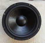
The subwoofer is the Tang Band W5-2053 with 2 Peerless 5.25" per enclosure.

Crossover frequency is about 300hz

Design Goals:

1 - Build a full range speaker capable of solid bass with smooth response to 20kHz

2 - Total internal volume of 3 liters including mid enclosure

3 - Unique striking look

4 - Ensure every possible square inch is covered by a sound radiating diaphragm =)

Driver Selection:

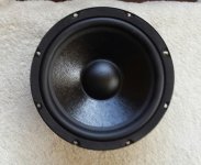
I tried a few different drivers but always knew I'd end up with the W5-2053, this thing is a monster and the bass it puts out from only 3l is astounding. Was an interesting driver to work with as it's response falls off a literal cliff at around 1kHz, so I used that to my advantage in the XO.

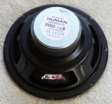
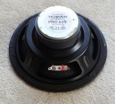
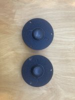
I had a pair of PS95's I'd been wanting to try out and was shocked by how good they sounded, so after trying some different drivers I settled on those. They were also welcome with the limited space I had to work with.

Enclosure design:

This was purely determined by 2 factors...driver and PR mounting dimensions and the strict internal volume requirement. As you can see it's all a tight fit.

Precise calculations were made initially using some triangle area calculators to ensure internal volume was at or less than 3l.

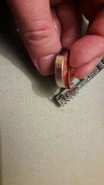
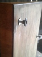
Passive Radiators ended up with no weight which resulted in a 56hz tuning frequency, more boosted than I wanted but adding any weight maxed out the excursion that much sooner. I was able to add 15 grams to bring it down to 50 but the passives were straining much sooner, as is the W5 easily over powers 2 5" PR's, really 3 or 4 of these would better keep up with 1 W5.

4fc1564dda2859958b7ce1e753d3f9ee.jpg


Another passive radiator issue I dealt with early on was "enclosure walk", using dual opposed passive radiators solves most of that. Also Sorbothane feet in 30 durometer further eliminated any chance of movement.

Enclosure Construction:

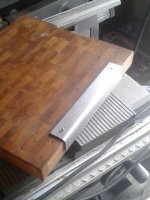
Construction is solid mahogany, angled joints are mitered, all glue construction.

4c8f2e5d69d3f00ca8f8cdeed49950b1.jpg


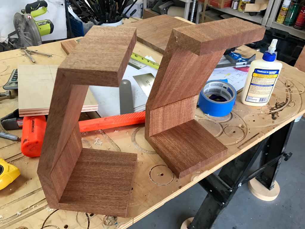
I made this CAD (Cardboard Accurate Dimension) to help with the initial concept, I also used it to check test cuts to ensure things were aligning and helping with angle calculations:

81b8cdfd423aa56d63b26530fe479d60.jpg


Plywood test cut that was perfect, this locked in all my angles on the table saw:

1268acea905adbcac527e6180faf938d.jpg


Tape held it all together:
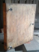
85f0b69016f6c1abaa57afe5fde51d44.jpg


In Mahogany:

8e7f8039e6dbb6e14c3819c7f4a226af.jpg


a5cdf2c6e89df81a47d6b5317e373c41.jpg


9da95a960463cec299a8aec365712423.jpg


I made the cut out of one board to match the grain:

2fa788ad1ab2ae44b614553509096577.jpg


Attaching front baffle:

b9cc02427e7f96da66522fe28a281757.jpg


My cut list:

97dac6c51eafaf6fe52018f47294e8e8.jpg


Test fit:

4cabc1cf6c36a0cd6b57acf895ac4a54.jpg


0deb65e447b8ac65222341300f7204a8.jpg


Clamping and gluing the baffle:

54fd1782c2cad5d4ecb88d60e847d736.jpg


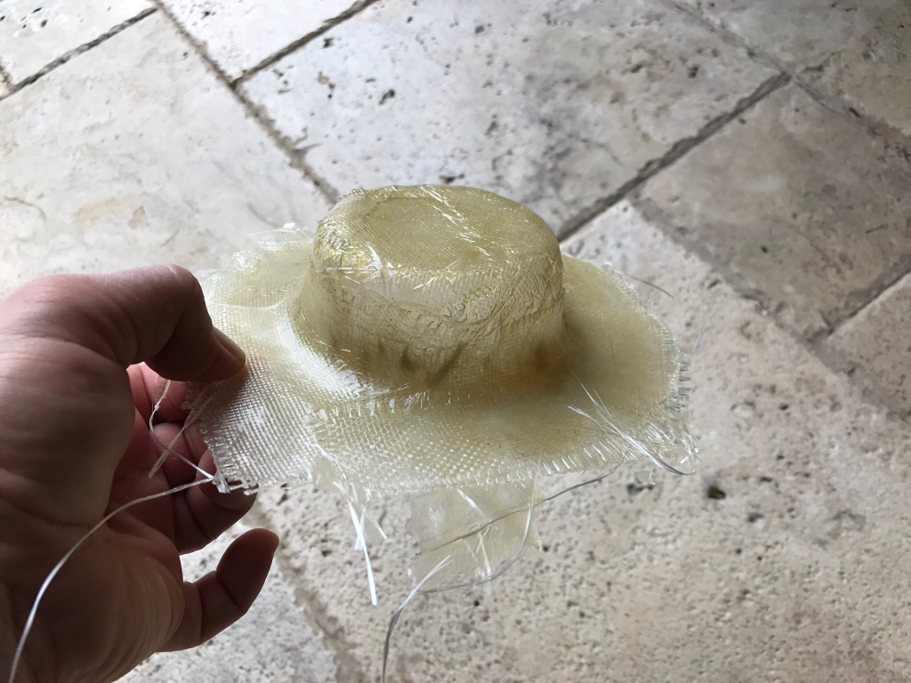
Before I attached the sides I wanted to finalize the mid enclosure, since the PS95 needed no airspace to play to 300hz, I molded a tight fitting fiberglass enclosure.

I started by mounting the driver into a board just like I would in the final enclosure, then I built a makeshift mold using layers of alum foil and masking tape:

a73fff4bee3aa7a63c9390c061fe8975.jpg


Fiberglass matte:

7fba5e98bbd1588342d75a66b7787f70.jpg


Polyester resin:

b51008b2988a675e45e5d8a2b24be1cb.jpg


Wala, about 5 layers:

0eeb43e6854b70e245c663eb4be2e696.jpg


Removed from the mold:

6df5f152534df84893aed73ed88ed14d.jpg


Trimmed up and painted:

04f3ee81c202e35b57ca10a18158a260.jpg


8387332c78df5c4de633e75b73140370.jpg


Built into the mold was a 3/16" Sorbothane disc which creates a CLD treatment to the back of the enclosure, as the driver is screwed down it loads up on this viscoelastic dampening medium and greatly acoustically dampens the mid enclosure. I tested this and it works well:

db60538a1bc7e45f7e8bcd4a413482d2.jpg


33d5c3b95fb58f5d984608208331cdd4.jpg


c7f0a5c2cdf3ce081af99dacf290c83d.jpg


Mounted, it is attached with silicone adhesive and some screws for good measure:

697d23b887fa7d0f96c4c9dee318a1ba.jpg


4cee916f504a2618ae59f2b1253b199a.jpg


50b5039c9f6580fb7e92cbf6d2956c4a.jpg


Time for some sides:

076ed62e8b4ec41e7b7b27e025e8cbb1.jpg


All panels glued and flush, ready for some roundovers:

fb3d22b04dfebe273888b12a44610792.jpg


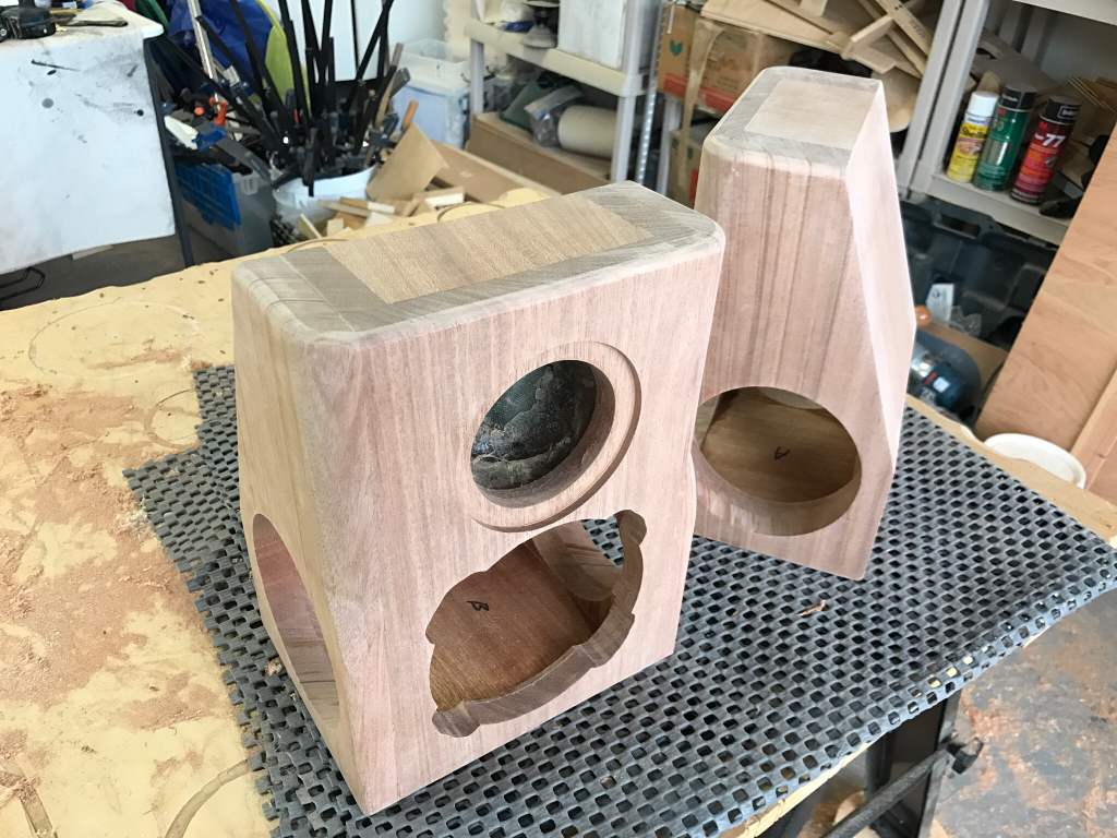
I didn't have enough room for a full 1" round over like I wanted to do, but fortunately the W5 wouldn't benefit from it, so I developed a way to do a tapered round over using a wedge for the router bearing to ride on:

ada9a83f721c2cc14cc55e30b1ef2bce.jpg


f5b076ec57774a1f2503bb6ffe29fd4c.jpg


3aaba84327fbbd1e72357d666ded2759.jpg


This created a precise contour that cleared all driver frames.

And all round overs and treatments done:

6ed4a70f54381641477767bafa96fd59.jpg


a271fbe1a7805f6a0aa99fbf06986ba3.jpg


And a coat of Danish Oil, BOOM! There's the grain!

2e343d87a9ef8b38dbf5379908ea73d5.jpg


25fb16c2765d91a0e2d05a1f34599015.jpg


And after soaking in:
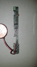
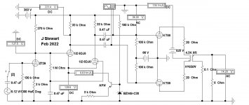
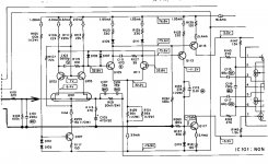
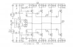
5e82d51e2812b997b954339f6aa365f6.jpg


Crossover Design:

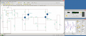
I tried many designs including various frequencies and electrical slopes before finalizing on what I have here. I ended up with 18db on the mid and 12 on the sub. Since I was crossing over at 300hz I used an Lpad to not only balance out the more efficient PS95 but also as a baffle step function.

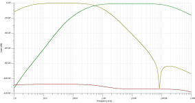
The PS95 also displays break up bad above 15k but it starts around 9k, I implemented a 12db low pass sound 10kHZ which rolled off the top end nicely until it was voiced the way I wanted. Not sibilant but with air and space. Indicators are 18ga, all capacitors are electrolytic except for poly in the PS95 top end roll off and the 1uf listed in the schematic.

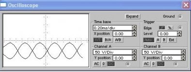
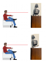
I tuned this until it had a flat response but like that the highs just fell flat, despite loving the FR plot it just didn't sound rift, so what sounded best is what's below (near field at about 12" centered on the mid.

51c7e01586a2e208006688a128e0793d.jpg


6ca7aee46c4d3a42185d2aeab1ad0ffe.jpg


ce57fb1ffb5fe517440f1b7045ab53a1.jpg


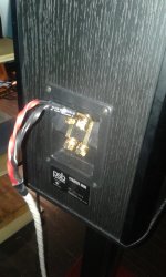
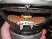
Installed, tight fit!

a19756f3eabdfee990ca2050935b0034.jpg


Conclusion:

a9a3af37b153d7699328bd4fdafcc99b.jpeg


facf36d638030fb23a97b0a34caa1fb5.jpeg


93265556d4f0ee37b63b44a564d42080.jpeg


43be77243e0c35b941a769886a99b2d8.jpg


cceee327debd1b88a1355c9cca20a21b.jpg


6fde07870c8fe1e96c174534bdbcc1fc.jpg


These were a blast and they've been my go to speaker for casual listening the last few weeks! Everyone that has heard them has fallen love with them, so I'll be very interested to hear how they hold up at Indiy. The bass is shockingly powerful for 3 1/2 inch diaphragm, they put out comparable bass to many 10 inch sub offers that I've heard and built in the past, they will easily trounce most 8" on the market.

This is the first time I've used a "full range" driver and I'm very pleased with it, working with the top and was challenging but once I got it rolled off and minimized the break up it really smoothed out and is quite surprising how much crisp clear treble this driver can produce. Imaging is excellent, they sound great near field as well as 6 to 8 feet away, they have no trouble filling a room with sound and I have even fooled a couple people into thinking they were hearing the Rally Sports when in fact it was the microfarads.

Most notable, ironically, is their bass performance. In fact they have too much bass, due to the limited excursion capabilities of the passive radiators as well as the very small air volume, tuning frequency is high and the bass response quite boosted below 120Hz. Though they rolloff below 45 Hz, that's enough to encompass the majority of all content in just about all my reference music and other music that I enjoy listening to regularly.

This has been an eye-opening venture into the micro speaker category, and I'm looking forward to doing some more small builds in the future, and another version of these with slightly more airspace with a more capable passive radiator.

Thanks please let me know your thoughts and if you have any questions!

Javad

LJM Preamp Recommendation for L12-2

Hi,
I'm looking for a preamp recommendation for a pair of LJM L12-2 power amp modules. I've considered a few options such as the LJM Preamp P9, P8, P7, or just a volume pot, but I'm not sure which way to go. @ljm_ljm please respond with some recommended combinations.

I've built LJM L12-2 amp boards, MX50 SE amp boards, and a power supply. All fun kits to build and no issues.
Thank you

Benefits of asymmetrical 4th order Linkwitz-Riley cross.

Hello, I've found somewhere a description of a crossover design in which there was: 'This crossover is asymmetrical 4th order Linkwitz-Riley at 1750 Hz. The slightly steeper tweeter slope along with a slightly shallow woofer slope helps to align the listening axis with the tweeter.'
I'm such a newbie in crossover design and I'd like to go into detail with on-axis and off-axis effects of various typologies. What exactly does that phrase mean?

F5 Turbo V3 +/-58v rail voltage questions

I am working on a pair of F5T V3 mono blocks. The toroidal's secondary voltage rated 40v/1000VA, the +/- rail voltage going to be 56-58v loaded.
What particular value of the component needed to be change to accommodate the higher rail voltage? NP mentioned that the Jfets see about 1/3 of the rail voltage from the voltage divider R25 and R27.
If I change R25 to 12.8k, R27 same as the schematic value 4.75k, assume the rail at 57v then the Jfets will see 15.43v.
R5, R6 1k resistor for the BJT 2SC4793 and 2SA1837 but these two items just can't get them any more. If those two cascode BJTs substitute to MJE15034 and MJE15035, R5 and R6 can be the same value 1k with 57v rail? And the above BJTs are suitable candidate?
The feedback resistors R7 through R10 value would be adequate?

I do try to search but just can't find the match or I just missed. The moderators feel free to move if needed.

Attachments

  • art_f5_turbo-page-12.jpg
    art_f5_turbo-page-12.jpg
    382 KB · Views: 764

Where does one start to learn?

I am looking for book recommendations or links to various sites that could offer a form of education when it comes to better understanding electronics and amplifiers. I have a background in Chemistry and can read a schematic pretty well BUT where I fall apart is comprehending the schematic. Why is that capacitor there, why is that resistor there, etc. I have toyed with the idea of taking some college classes but being a teacher and dad funds for that are not available at the moment.

Help with "Interface Electronics" portable audio mixer

I purchased an "Interface Electronics" audio mixer from a local ham fest last year. It came in a flight case but had no power supply or manuals. The man i purchased it from told me how to use it with any 48v power supply. I took it home and fired it up, and to my surprise the sound quality was not only good, it was amazing! I tried researching this company so i could pick up a service manual and at least get some specs on it. The board has a very distinguished sound....a good cross between API and Neve.
All boards fit into a PCI looking slot that runs along the bottom, connecting all boards. I decided to be an idiot one day and start pulling out boards to look at them...when the power was on. It has 8 similar boards for the individual 8 inputs, then an oscillator board and finally the main board with meters and master controls. I pulled out this board and then reset it in the slot...only to short it out and cause it to smoke. I found that i fried the first resistor in line after the connection to the power supply, only i burned it so badly that i cannot read what value it was to replace it. I had to blow up the one board that there is only one of. Any one have any idea of where i can find a schematic for this puppy? I have taken it to a local pro audio repair guy who found the resistance value but says there are other things wrong with it as he is finding DC all along the op amps implying a short. This is not a very expensive board but means a lot to me and my sound, any help would be greatly appreciated, if you would like to see a picture of the unit, please contact me and i'll be glad to send it to you. Thanks all!

I´ve built a 3A5 preamp

I´ve built a 3A5 preamp:

Gyrator Schema.jpg


3A5-parallel-triode-DHT-preamp.png


Test av 3A5 Pre.jpg


Underifrån.png


But what I do not completly understand is the Gyrator.
If I set the voltge (Anode) to about 100v,the current through the tube halves is 10mA 20mA per tube,maybe a little high.
And if I set the current to 5mA /triode ,10ma per tube.The voltage is about 60-65 v at anode.
The question is how do I set it?
By the way This one is microphonic....

Micromega Stage Cd Players eprom and boards.

Micromega Stage Cd Players eprom and board versions.

Hi I wonder if you could help me with a couple of questions please.

I have a number of Micromega Cd players ranging from Stage 1 , 2 and 5.

Some work fine some are in disrepair.

I have noticed on the boards there is an IC chip which I gather is the eprom for the drive and laser?
They have different version numbers written on them in biro.
Am I correct in presuming the later the version the better and more reliable it is.

It also seems to be that the later ones are on boards that have a little dog leg protrusion for the headphone socket.
So am I also correct in presuming the dog leg ones are later boards also?

I have a Stage 1 with a solid board and ic V.1.4 and a Stage 5 with the dog leg board (for the headphone) with ic V.3.22

Any info on the above would be great as I plan to construct a player with all the later versions of above.

Thanks

Cabinet resonance - when and why NOT to fight it?

Hi, the usual wisdom for speaker cabinet building holds that the more one can eliminate cabinet resonance, the better. The theory is that the only thing than should resonate is the driver diaphragm/cone and everything else should be damped and as made rigid as possible.

Having recently done some reading on Bud Purvine's approach to cone treatment and some more reading on resonances at Mother Of Tone presents: The Altmann BYOB Site, I wonder if there are people in DIYAudio community who tried not to eliminate/reduce cabinet resonances but rather accepted them and tried to make the best use of this acoustic phenomenon.

Clearly, a speaker cabinet is different from a musical instrument which relies on resonances to achieve its characteristic sound, but there are still people who believe that using wood (e.g. birch plywood) makes speaker cabinet sound more "musical" than MDF or concrete or other artificial material...

In addition, there is the issue of lacquer/finish of wood which has impact on the sound.

Has anyone here done some off-the-mainstream experiements in this direction? What were your results?

Thank you for sharing...

Peter

P.S. I should mention that personally I prefer to listen with my ears than with measuring instruments. Therefore, I am not against "colored" sound if it is pleasing. Also, having wonderfully linear response curve in anechoic chamber (or other not real-life scenarios) is less relevant for me.

Little Tube Amp...K=12G

I can't leave this little tube amp I built this week alone.....Got up early this morning and replaced the crappy volume control with an ALPS 100KAX2 that I received from Parts Express yesterday. Had to make a little "tombstone" for it as it was much larger than the stock VC.....Also swapped out two of the tubes with NOS tubes. Lowered the very slight buzzing to near nothing. Waiting for two more I ordered to arrive to do the other channel. Still loving this little 8 wch, $100 amp!

Attachments

  • P1050163.JPG
    P1050163.JPG
    592 KB · Views: 135
  • P1050164.JPG
    P1050164.JPG
    519.7 KB · Views: 124
  • P1050165.JPG
    P1050165.JPG
    278.6 KB · Views: 127

Ohm 1000 Tall Speaker Crossover Upgrade. I have a 12 year old pair of Ohm 1000 speakers and would like to consider upgrading the crossovers.

I have a 12 year old pair of Ohm 1000 speakers and would like to consider upgrading the crossovers. I would be most grateful for any tips/pointers members may wish to add. I am aware that two crossovers exist, one attached to the inside of the speaker cable connectors at the bottom of the speaker which also enables a base boost facility. The second, high-frequency crossover is encapsulated within the sealed unit above the base/mid driver unit above, which incidentally looks as though it may be a so and so to access?
I am a novice DIYer living in the South of England UK. Fortunately, I have a friend who has offered to help who is a very experienced retired electronics engineer with oodles of experience and equal amounts of patience in explaining things to me?
Grateful for any tips you may have with this project.

I have owned these speakers for 3 years and do like them as they are relatively WAF and easily placed around my mid-sized room but would very much like to try and improve the SQ. I am driving them with a Hagel H190 sourced with streaming Tidal through a Magna HiFi Mano Ultra MK1 streamer soon to be traded in for a MK2.

LM1875 Integrated Amp w/ Phono Pre

Hello all,

I've just put together my first attempt at an integrated amp design featuring 2x LM1875 chips for stereo output.
For the source I've included a phono preamp design based off the Muffsy PP-4 (https://www.muffsy.com/muffsy-pp4) and a relay input based on another Muffsy product (https://www.muffsy.com/muffsy-relay-input-selector-4) that connects to the phono, a general stereo RCA input, a 3.5mm aux jack, and a 3-pin JST connector to integrate with a separate project I'm working on.
Relay control will be handled remotely using an arduino or similiar via i2c.
For power I've put together a ±25V linear supply that will directly feed the amp sections and also connect to a pair of LM7815/7915 to feed the phono preamp.

I plan to use a 4 layer PCB to help in managing all the different voltage levels present in the design.
The total package fits into a 4in x 6in rectangle and has been designed to easily allow me to cut the board and separate the amp section from the input.

I am curious to get the community's thoughts on this design and any suggestions for improvements. Especially around grounding; I tried doing the star topology.
My current audio reference is an Anker Soundcore 2 12W Bluetooth speaker, so I'm hoping I can improve on that for audio quality 😀

The schematic and layout should both be attached.
I haven't made gerbers yet, put could share those in the future if anyone's interested.

Cheers!

Attachments

At what point does omission become fraud?

I was just making up a set of short speaker test cables. I had a spool of CL rated 16 gauge "audio speaker cable" I got probably from Amazon, don't remember, to run my HT speakers. Nothing special. Well really nothing special as I just discovered, it is ALUMINUM WIRE, coper clad strands. OK, the box did not say it was copper, or say it was aluminum. But, it may be physically 16 gauge stranded, but not electrical. Kind of pushing the limits!

Are these drivers and this amp a good match?

Hello, my name is Raviv, I just started a small speaker design studio. my goal is to make a great sounding speakers in great looking, hand made and original designs.
so far my products are DML based + open baffle subwoofers you can check it out @ www.ravivstudio.com (currently we only sells locally in Israel)

Anyhow; my idea is to make an amplified full-range speaker stereo pair, I chose full-range for the benefit of simplicity and design freedom.
what do you think of that combination:

UPDATE:

Dayton Audio RS100-4 4" Reference Full-Range Driver 4 Ohm​

https://www.parts-express.com/Dayton-Audio-RS100-4-4-Reference-Full-Range-Driver-4-Ohm-295-378+

Dayton Audio DSPB-250 2x50W Class D Audio Amplifier Board with DSP​

https://www.parts-express.com/Dayto...lass-D-Audio-Amplifier-Board-with-DSP-325-126

1 -are they a good match for a small-mid size living room?
2 - do you think I can make a hi-fi amplified stereo speaker set from 94$ parts ?! 🙂

How to set amplifier output voltage to 2.83v for testing drivers

Some guidance w/b greatly appreciated.

I have a 3-way speaker with drivers (without crossover) and need to test frequency response of the 3 drivers in cabinet. I assume that the objective is to measure each using the same output voltage since the differing impedances, efficiencies and crossover goals will cause different loudness.

I bought an oscilloscope to do this and can see sine waves no problem and when driving my cheapo Lepai class D amplifier to 1/3 volume gain dB I can measure 2.83 volts on a simple DMM at 60Hz. But using the oscilloscope and my Denon receiver (AVR4306) I get a measurement in the millivolts Irregardless of the gain setting .. I'm going crazy.

I tried taking measurements without loads, dummy loads of 4 & 8Ohm and with drivers loaded. Same results. The only thing I didn't try was hooking the scope ground lead to actual ground as opposed to across the output terminals of the amps. But that doesn't explain why it worked on the Lepai with a simple DMM.

I did manage to eventually blow the Lepai with an accidental short. So now I'm reluctant to measure the Denon any further.

Could someone offer me with a simple sketch of the oscilloscope, amplifier & driver circuit so I can feel confident about that anyway?

Thanks in advance
Mike Wittman

30+30W on 8Ohm for everyday listening

Hi,

I would like to ask you a suggestion on a class D amp capable of 30+30 Wrms on 8 Ohm for everyday listening, with RCA and Bluetooth inputs. No eq or similar, just the volume. Possibly already in its case.


I’ll buy a separate AC-DC power supply.

Budget for the power amp only is 80 € approximately.

I will connect two full-range speakers FHXL with Mark Audio 11MS and they will be used for music and sometimes tv/movies.

Thank you,

Roberto

SMD resistor brand choice - Yageo, Viking, Ever Ohm etc.

I'm about to take the plunge and try having JLCPCB do my board assembly as well as PCB manufacture. I'm selecting specific part numbers from JLCPCB's inventory for given components on the board, and I'm looking for some advice on resistor brands.

For example, if I search for "10k 0603 thin film" a large number of options are available. The brands that I recognise (Vishay, Ohmite, Panasonic, Susumu) typically have an MOQ of 1000+. The brands that have reasonable (for me) MOQs are not familiar - Yageo, Resistor.Today, Viking Tech, Ever Ohms.

I'm assuming these brands are decent quality, given they're what JLCPCB keep in stock. Should I worry about which brand to choose, or will they all do the job?

Thanks a ton 😀

did you make anything this weekend?

I'm doing a isolation board for my DAC.

One of the simplest cost effective DIY.

Maple butcher board $75 (as new)
Brass screws $6
Stainless steel free
Footers also free

Better sound - priceless

This board has been with me forever. I'm giving it some feet and a little bling. It will be finished with scotch brite the next time. I'll find some better footers too. These ones are a bit flimsy.

The maple likes breaking off brass screws. Its tough stuff. I need a hand driver to snug those in.

Attachments

  • 20220227_151855.jpg
    20220227_151855.jpg
    208.2 KB · Views: 114
  • 20220227_151906.jpg
    20220227_151906.jpg
    193.1 KB · Views: 122
  • 20220227_152049.jpg
    20220227_152049.jpg
    269.2 KB · Views: 116
  • 20220227_152129.jpg
    20220227_152129.jpg
    185.7 KB · Views: 113

Most Neighbour-Friendly Speaker Position?

I'm designing some 2-way/3-way speakers and am starting to think about where they may be positioned in my relatively small room. One unfortunate but very real issue is a neighbour who works nights, and a thin party-wall which allows quite a lot of sound through. I'm wondering what I can usefully do (if anything) with speaker placement.

The speakers will not have any rear ports, so maybe they'd be best located actually by the party-wall, facing away from it? Having them closer to the neighbour seems counterintuitive but presumably the primary sound being directed away from them would be beneficial. Though... in reality perhaps not very much due to all the room reflections and diffraction etc etc.

TBH I'm a bit pessimistic of it making much difference so (before I start disassembling furniture to move it all around) I wanted to ask what people have found or know about this kind of thing. Human perception of SPL doesn't seem especially linear or objective, and that speaker arrangement would mean a less desirable layout for the rest of the room, so not sure the likely results would make it worth going there?

Thanks,
Kev

3-Way home cinema

Hello,

I am planing to build a three way speaker for my upcoming home cinema in the style of an Genelec 1237A. That means 12 inch bass + 6,5 inch midrange + 1 inch compression driver. Midrange and compression driver should run in a waveguide. I am planing to use the Limmer 630. To match the compression driver to the Limmer 630 I need to print an adapter with my 3d printer.
Opening of the Limmer 630 for midrange is 13cm. That means midrange should be in this size range (inner surround to inner surround)
Limmerhorns - 630

Planned crossover frequency is about 250-400Hz and 1,5khz - 2khz.
The chassis should be in WTM arrangement (from top to bottom) with tweeter aming to main listening postion. The speaker should be placed directly on the wall with the front angled 7° to the bottom. This should look like this:
https://s19.directupload.net/images/191224/cvmdccp6.png

The 12 inch woofer should run in about 20 liters closed box and will be crossed at about 60-80hz to an DBA system.

The system should run completely active with an Hypex fa253.
The system should be able to run 105db reference volume at main listening (3 meters away which means about 10db loss).

Current Favourites for the 12 inch woofer:
BMS 12S305
BMS 12N804
Beyma 12LEX1300Nd
PHL 4310Ndu
PHL 4531
Eighteensound 12NTLW3500
Eighteensound 12NLW9300
Ciare 12.75LW-44
Faital 12FX600
B&C 12PLB100
A&D SCB12N500XL

Current Favorites for midrange:
PHL 1120
PHL 1660
PHL 1752Ndu
Ciare NDK6-1.5
Faital 6PR160
Faital 6PR122
Beyma 6MCF200Nd
B&C 6MD38
B&C 6MDN44


Current Favorites for tweeter:
Faital HF108 (I am already using in koax system)
B&C DE360
BMS 5530Nd (HE)
Eighteensound NSD1095N

Now it would be nice to get some experiences, compares or measurments of the drivers mentioned above. Which woofer, midrange, tweeter you would prefer and why? Did someone of you hear the drivers mentioned above? How do you rate them? Or do you maybe prefer another one? Would be nice to get some experiences to find an decision which drivers to use.
Maximum sound quality is on first postion over maximum spl.

Selecting ohm load of drivers

Looking at components and efficiencies there is a big difference between a tweeter and woofer. I am currently planning a 3 way system with a passive crossover. And wondering if I should get an 8 ohm tweeter and 4 ohm woofer so that efficiencies go opposite of the resistance? Will more power get to the woofer this way?
Then what about the mid? I can go 4 ohm or 8 ohm and I would assume it will be coupled with the tweeter. So should I get a 4 ohm tweeter and 4 ohm mid to make an 8 ohm curcuit on top so my low end is 4 ohms? Then I guess parallel them to get 6 ohms to the amp?

This is driving me a bit bonkers and I definitely could be overthinking this. This does not take the crossover into account, so how is this stuff modeled ahead of time as a complete circuit so I know what amp to get.

SPDIF code

I am starting a new project to build a digital front end for a triamp.
I have already built an analogue system with a signal input filter, digipot attenuator for the 3 frequency channels controlled by an optical encoder followed by 3 stereo amplifiers.
What I am intending to build is a digital signal processor to accept a SPDIF or toslink signal from a cd transporter, a digital frequency filter, attenuator for each of the three frequencies then a dac before the stereo amplifiers.
I have looked at embedded processors and have the teensy 4.1 in mind with the arm processor, this to use for the DSP and dac unit.
I am after help and advice as my programming experience is limited to assembly and pics which I used for the digipots and encoder.
Hopefully I will use C on this system.
I am looking at the SPDIF protocol and see that the clock is built into the biphase data. Does anyone know at code level how to synchronise with the clock.
Any information would be gratefully received as I have to build up very slowly.

Human Pro 005. 8" Woofers. $120 shipped conus

Sold.

Also have Human 002 tweeter pair in near new condition. $95 shipped in usa.

Used in 2 ways with no xo on woofers (natural roll off ~1800hz). and only 10uf cap on the 4 ohm tweeter.
Also used as replacements in EPI vintage speakers.
Excellent condition.
1-2 ft3 sealed.
Check Human Speakers website.
Their specs, from website.
Fs 26hz.
Re 3.35 ohms.
Le 1.0
Xmax .35 inch
Qm 5.7
Qe .51
Qt .47
Cas 55 liters
88 db/1w/1m
Stiff paper cone, treated.

Attachments

  • 20190916_150713-1.jpg
    20190916_150713-1.jpg
    195.9 KB · Views: 355
  • 20190916_150701-2.jpg
    20190916_150701-2.jpg
    240.3 KB · Views: 348
  • 20190916_150620-1.jpg
    20190916_150620-1.jpg
    289.7 KB · Views: 334
  • 20190916_150558-1.jpg
    20190916_150558-1.jpg
    325.2 KB · Views: 333
  • 2B87484C-8269-46DF-BFBA-174F39CD9453.jpeg
    2B87484C-8269-46DF-BFBA-174F39CD9453.jpeg
    415 KB · Views: 109
  • 3C79DDE8-A0E8-4988-A476-7C2AC135E58C.jpeg
    3C79DDE8-A0E8-4988-A476-7C2AC135E58C.jpeg
    575 KB · Views: 116

Help needed : inport LM3886 and OPA1611 and LME47290 in L-Tspice ... earn 1000 virtual kisses

Hi, can anybody please , please help me to import these 3 Componets in LT-SPice.

P-Spice is not working on my computer, because I have only a 32Bit System and its to slow.

Please , I know there is a member which can help me , please.

  • OPA1611
  • LM3386TF
  • LME 47920

should be in to Lt- Spice.

love regards and 10000 vitual kisses if you can help me😍

Help needed by building a subwoofer filter and looking for a possibility of a sharing Design for testing

Hello members, :wave2:

actually I work on my first LM3886 Amp and for this I want to have also a subwoofer filter.
So I have later a 2.1 System.

I found this and I be very interessed on it:

https://www.lcaudio.dk/pdfs/subfilter.pdf
Does anybody build and make this in this way by EasyEda or KiCad an want to share
the PCB Gerber Data with a young electronic interessted girl ? 😉

I want to test it, and it was on first step easier to get a finished PCB
for testing and understanding.

kind regards

I am looking for ideas for a DIY amp/pre-amp or integrated.

In the early 90s I build a power amp (Erno Borbely design) and after completing it found that every once in a while it would oscillate. I didn't want to spend the time to troubleshoot it so a friend bought it, thinking he could fix it. He tried but after a while (believe it or not) gave up and let it oscillate (which was pretty rare). Lately I've decided that I want to give it another go and build my own amp again. I bought the Randy Slone book and thought about using one of his designs but see some people (on this forum) were having trouble getting the designs to work properly. Could I get some suggestions for a great sounding, reliable solid state design that puts out 20 to 60 watts. Especially from someone that has actually built the referenced design. Thanks in advance.

biamping

It's a bit strange that I can't find wattage specs for Nad 325BEE's @ 4 ohm, were they just not published? I just know they are rated 50 for 8.

Anyone know? I'm going to try biamping these and would it be fine to use two amps with fixed gains that have that large of a gap in output ratings?

I knew the stratus line wasn't the most efficient having had silveri before. The mini are 88 db efficiency to be specific https://content-psbspeakers-com.s3.amazonaws.com/uploads/2021/03/stratus_brochure.pdf 250x2 hardly seems as strong while straight wiring them with the standard factory jumpers. I bet the mini would like two of the larger amps. Thats 500 per side if you weren't keeping track. It seems a little crazy for such small 2 ways.

I also noticed the amp gets quite a bit toastier temperature wise while playing the psb minis. Configured that way. Its always stayed luke warm prior to these. After playing it for hours, despite weather the speakers were 4 or 8 ohms. I consistently use both types.

Attachments

  • 20220225_234638 (1).jpg
    20220225_234638 (1).jpg
    244.7 KB · Views: 103
  • 20220225_234611.jpg
    20220225_234611.jpg
    304.5 KB · Views: 103
  • 20220204_132943.jpg
    20220204_132943.jpg
    252.9 KB · Views: 111
  • 20220225_201343.jpg
    20220225_201343.jpg
    228.1 KB · Views: 106

Simple active filter design for 2-way

In this thread I'm documenting my development of an active filter for a 2-way design.

Purpose:
High-pass & low-pass filters at around 500Hz, for a 10" woofer + 3.5" wide-range.
The filters will be 2nd order (Sallen Key, unity gain), and that can modified by adding more stages.
By modifying component values it should be pretty easy to reconfigure for different cut-off frequencies and different Q, and the same basic layout can be used for high-pass, low-pass and notch versions.

Additionally, I wanted to challenge myself by using discrete buffers instead of op-amps. An earlier attempt was only marginally successful: single BC850x based buffers were usable at low volume but had too much IMD. In the latest version, I've been able to significantly reduce THD, and IMD should also be much lower as well. It is also far less dependent on volume. As long as component values for filtering are within reason, it doesn't even have to be push-pull, which simplifies things a lot.

Even at ~0.0005%THD, I still haven't been able to match a NE5534 version that I simulated for comparison. However, noise performance is about 6dB better.
By using N and P MOSFETs configured as Sziklai pairs, simulated THD measures around 0.000x% @ 1V at a few different frequencies from 100Hz to 2kHz that I've tested, for both HP and LP versions.

The circuit is not optimised yet, and doesn't include any pre-amp section or volume control. The previous prototype used a dual-gang pot for volume, but ultimately I'd prefer a switched resistor topology. The order of the stages: gain, filtering, volume, is TBD.

I'll have to measure the speakers again to see if they need anything different like a Linkwitz Transform, shelving filters or notches.

Filter Q:
I'm keeping the slopes gradual at the moment, avoiding excessive overshoot and ringing. I suppose that even if it's hard to see on a linear scale, logarithmic ears may be sensitive to it.

Overlap and gain and phase at XO point:
TBD.
I've manually played around with the exact slopes to get something "looks" right on a virtual oscilloscope, but I'm not sure what the combined response will look like in the real world just yet. The speakers are in separate boxes so the geometry is not fixed. This is another reason why I'm careful to avoid ringing: there is no guarantee that it will cancel out, so each speaker has to have smooth output, independent of any 'corrections' from the other speaker.

Total output noise is about 500nV @ 20kHz for the low pass version, and 800nV @ 20kHz for the high pass. However, that is likely to get swamped by power supply noise for the version shown.

Attachments

  • active-filter-LP-500Hz-sziklai1.png
    active-filter-LP-500Hz-sziklai1.png
    58 KB · Views: 223
  • frequency-amplitude.png
    frequency-amplitude.png
    15.6 KB · Views: 217
  • lowpass-THD-0-0007.png
    lowpass-THD-0-0007.png
    11.4 KB · Views: 151
  • total-noise-PSU-highpass-lowpass.png
    total-noise-PSU-highpass-lowpass.png
    14.8 KB · Views: 207

EQ with bridge amplifier

Hello everybody .
I wonder if the thing I thought has a foundation and is feasible but above all if it offers advantages over other methods, sorry if I explain it in spans.
let's consider a bridge amp with the two perfectly identical branches, these work in polarity opposition.
let's pass the signal intact on the branch1, the branch2 we can use it to do EQ, but how? .
could one way be to do it digitally? I can store in a memory how much the signal passing in branch2 must be attenuated which, added to the signal passing in branch1, equalizes me.
I imagine that each digital line that goes to the DAC and then to branch1 must be matched with a line that goes to another DAC which then goes to branch2.
I also imagine that you have to memorize all the frequency response from which to fish what you need to match the signal to be equalized.
at each zero crossing of the current on the loudspeakers the branch1 and branch2 functions are inverted.
i am not expert on this subject so i don't know if you can understand or if i wrote some errors.
What do you think ?

Transistor tape recorder: convert speaker output to line output

Hey diyAudio community. This is my first post here so I apologize for any noobness.

Background: I recently got a transistor tape recorder that I fixed up and I think it sounds awesome when I use it to record drums. It's certainly textured and lofi in an exciting way. But the best part is the wow and flutter is terrible (lol) so long sounds like my cymbal come out super drunken and wavy while short sounds aren't noticeably changed. I think it's a cool effect that I want to be able to explore more, but the recorder only has a built in speaker so I can't record the tape to digital to work with it. The speaker in the recorder is labeled 8ohm 0.1w and I think it's powered by a 9v battery. There's also 3 C batteries in there but I think they power the motors and the record and erase heads.

Questions: can I use an audio transformer to convert the signal being sent to the 8ohm speaker to 600ohms and connect that to an 1/8" output jack to connect to a daw? Would using a transformer even make sense to try to load match the output to line level or is there an easier way? I want to use a switching jack connected to line and speaker level before the transformer so the speaker can be engaged for monitoring when there's nothing plugged into the output jack.

Thanks in advance for any help you can offer!

2022 Yukon Denali Bose subwoofer dump

Hey all,

I ordered a Yukon Denali 5 months ago and it just now arrived - Micro chip shortage. . I am speechless its an amazing truck!

it has a 14 speaker bose system, As I was expecting the bose subwoofer is not even in the ballpark. the rest sound ok, I can hear the speakers fighting to create bass and they just can't. I have a fair bit of experience building and wiring some high-end car audio systems back in the 90s and lots of current experience with audiophile home systems. I know things have changed since the 90s🙂

Originally I was thinking I would find a place to do a simple sub install, but the more I ask around, the less I trust anyone to work on this thing, they just don't seem to know what they are talking about or are familiar with with these new trucks. I found the Bose sub in the back left quarter panel, and I was surprised to see the fuse box right next to it, got me excited thinking that I could mount AND wire the amp right there off of the fuse box, or close by anyway. Thoughts? I have no idea what AWG wire is there but assume I would want at least 8awg. I had visions of having to run a power supply all the way to the battery. I suppose that is still probably ideal but I would prefer not to if I can help it, it sure is a far distance. Also, it appears I can just get an amp with high-level inputs and unplug the bose right there?

I plan to run a small 200-400 watt RMS amp and then build a small ported enclosure for a 10 or 12-inch subwoofer. There really is not much room with the 3rd row up.

Any thoughts or experience with the wiring back there on a 21 or 22 yukon??

IMG_2655.jpeg
IMG_2654.jpeg
IMG_2636.jpeg

europower ep2000

hi friends. i try to repair my amplifier but i stuck on silly error. on d5 and d8 i cannot get 15v. i change zeners but still same problem. any idea why i cannot get 15v from them?

it was burn power transistors 5200 and 1943. i change them and test it and see that 15v not coming. i check driver transistors too they are ok.

thank you for all answers.


ads.jpg

unusual failure mode for a speaker driver (at least for me)

someone in the family (carries half of my genes) run our trustworthy and reasonably loud Logitech z-2300 2.1 system (with smallish 2-way speakers instead of the original satellites have have gone past their useful service life a long time ago) at a small party for multiple hours at full volume and at some point it lost the bass output altogether.

He got back home and I wanted to see what had failed. The amp board looked fine (no obvious burn marks or signs of magic smoke), the 8" driver in the subwoofer looked fine. There was just a tiny bit of sound coming from the subwoofer and the heatsink of the amp board got rather warm rather quickly.

I had a closer look at the element and checked it with a multimeter: it showed it was practically short circuited, which certainly makes for a bad speaker driver. However, the place of the short circuit was a surprise to me.. the tinsel wires going from the connectors to the voice coil were touching each other quite close to the connector side. There seems to be more slack in them than I would have expected and I would have expected them to have some kind of insulation on them. Perhaps it was brushed off with the friction from repeated contact or perhaps it was running too hot or something.

Separating them brought the sound back, now I just need to make sure that won't happen again. I was glad to find out the amp didn't mind the short circuit. The Z-2300 is not exactly an audiophile device but for this purpose it works fine and can take a lot of beating (usually).

Attachments

  • PXL_20210627_201029010-small.jpg
    PXL_20210627_201029010-small.jpg
    191.7 KB · Views: 255

Looking for alternatives to the Motorola KSN1001A

Hey all,

I recently decided on the Motorola KSN1001A as the tweeters I would use for a makeshift LRAD that I would use to deter people off of my property. The problem is, everywhere I look, it's always attached to a somewhat steep delivery price so I was wondering whether anyone here would know of any other tweeters with similar specs that may actually ship to the UK without an annoying delivery fee.

Thanks in advance.

Twisted Pear Audio is moving!

Hi all. My family and I are going to moving to a new house in January.

In order to prepare for this, I am going to stop taking orders on the web site starting December 23rd, until I can get settled in (likely early February).

Once I am able to fill orders again, I will re-enable sales. I will continue to accept orders until the 23rd.

Thanks for all your support over the years, and here's to a happy new year for all!

For Sale Headphone-Amps: LPA-2, LPA-2s PSU: PWS-04a V2

LPA-2
http://funk-tonstudiotechnik.de/LPA-2 englisch.pdfUsed but in very good condition.
60€

LPA-2s
http://www.funk-tonstudiotechnik.de/LPA-2S-englisch-300.pdfLike new, only briefly used.
70€

PSU PWS-04a V2
Manual only available in German
http://funk-tonstudiotechnik.de/PWS-04a_V2-2011.pdfUsed but in very good condition.
60€

I have only one Potentiometer.
ALPS RK18 AX 21-Detent

Each HPA comes with SIA-5 debalancer.
This allows the HPA to be connected directly to a balanced source.

The prices are plus shipping from Germany.

I prefer shipping to EU (because of customs).
But worldwide is also possible.

Attachments

  • HPA.jpg
    HPA.jpg
    525.2 KB · Views: 119
Projects by fanatics, for fanatics
Get answers and advice for everyone wanting to learn the art of audio.
Join the Community
507,747
Members
7,886,491
Messages

Filter

Forum Statistics

Threads
406,156
Messages
7,886,491
Members
507,747
Latest member
puma1824